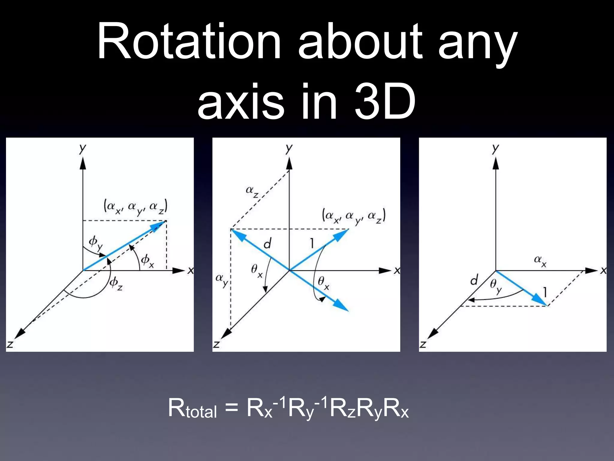
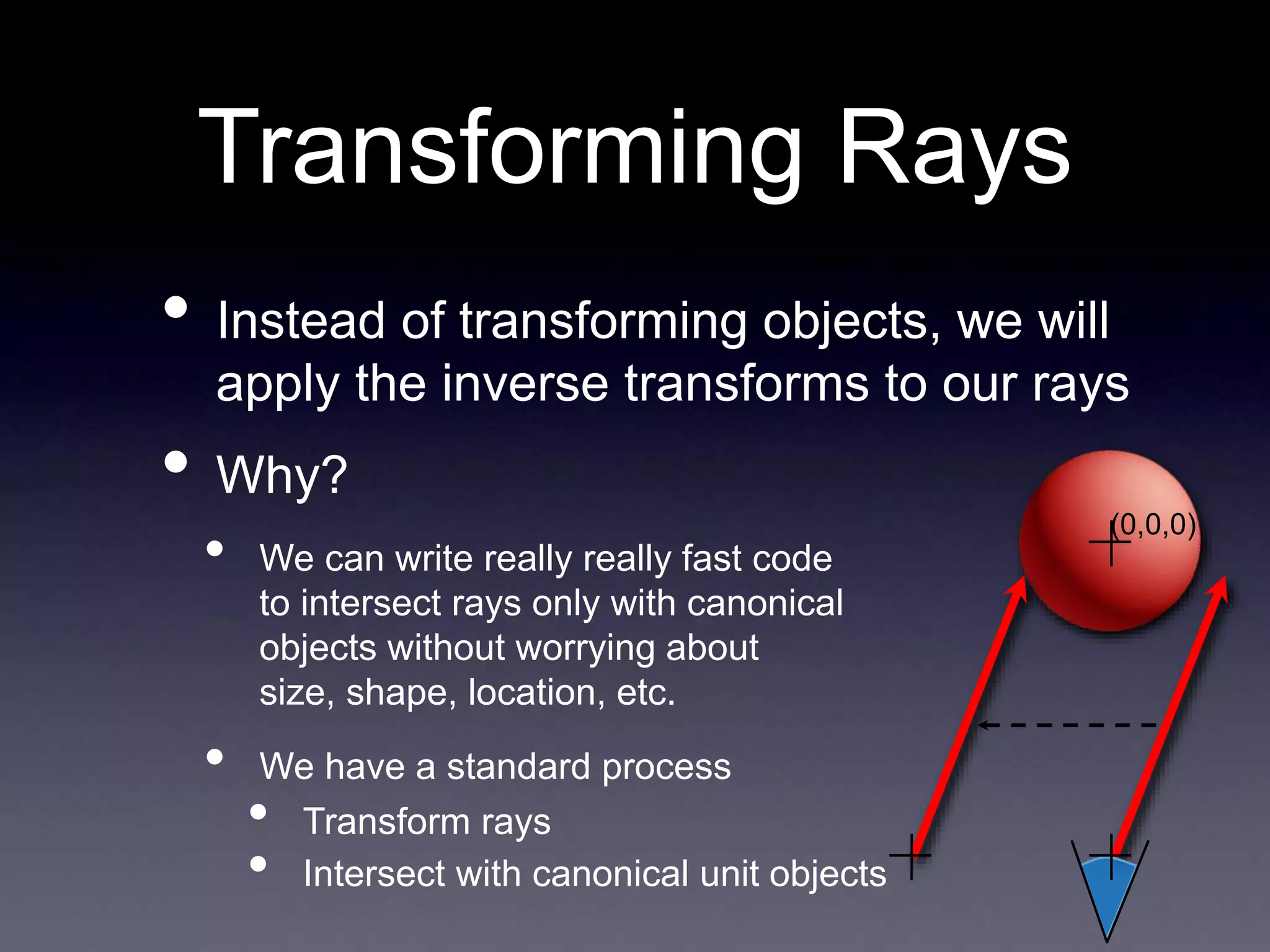
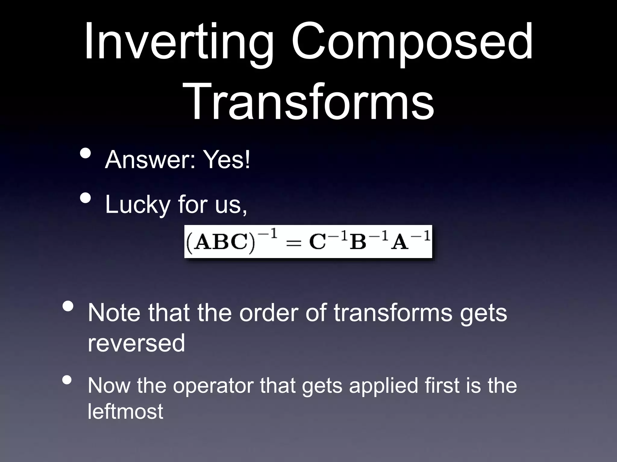
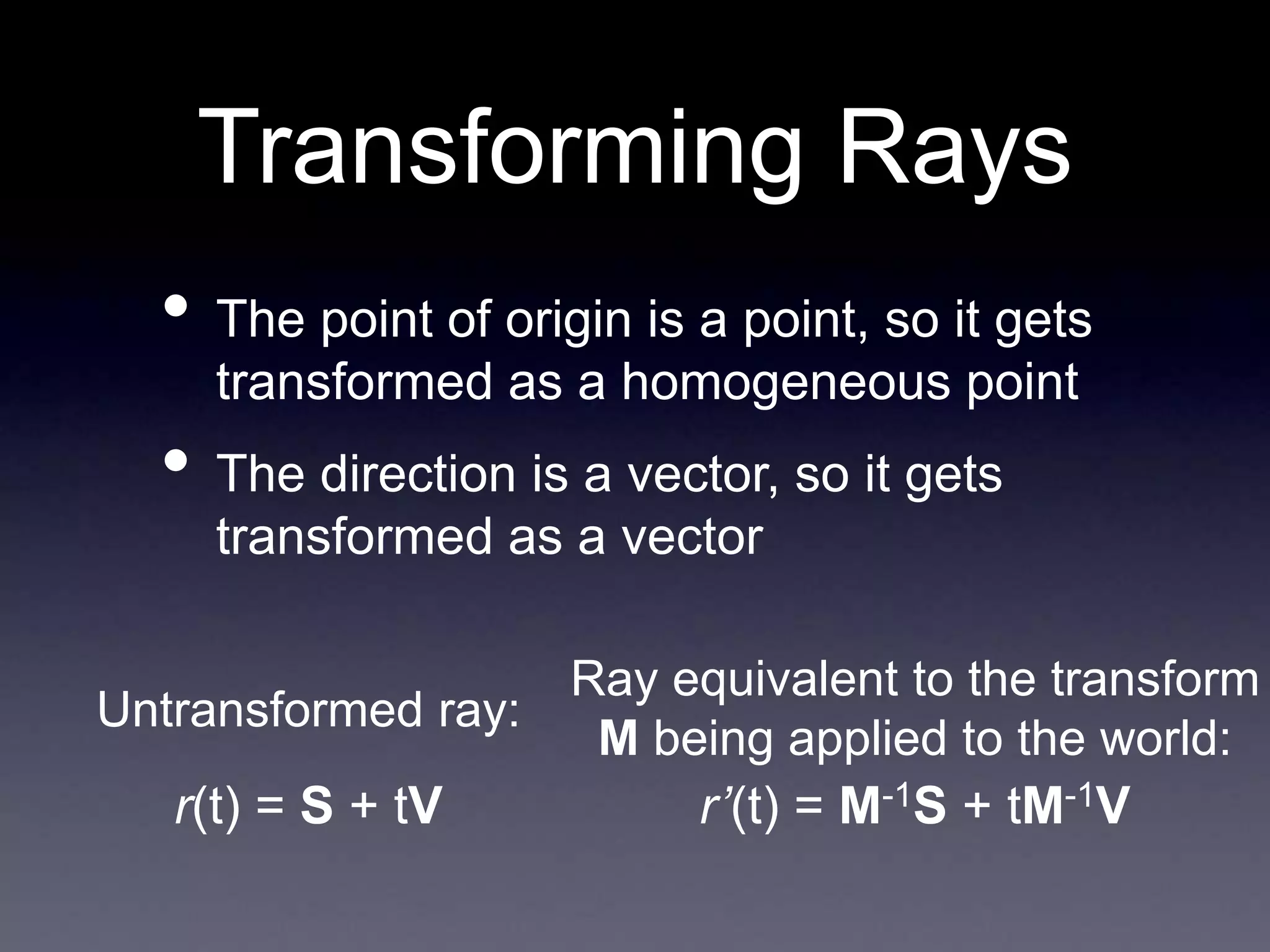
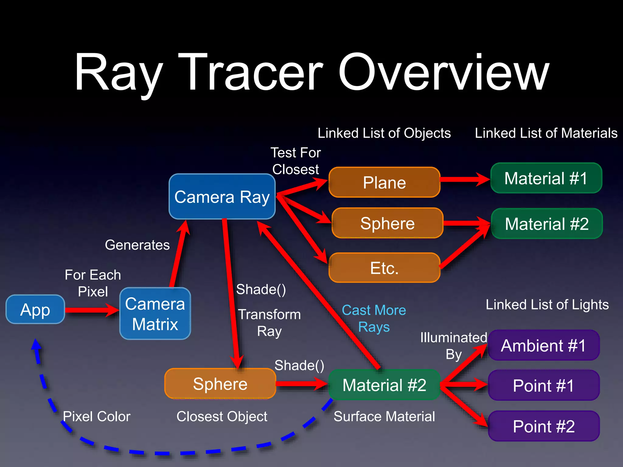
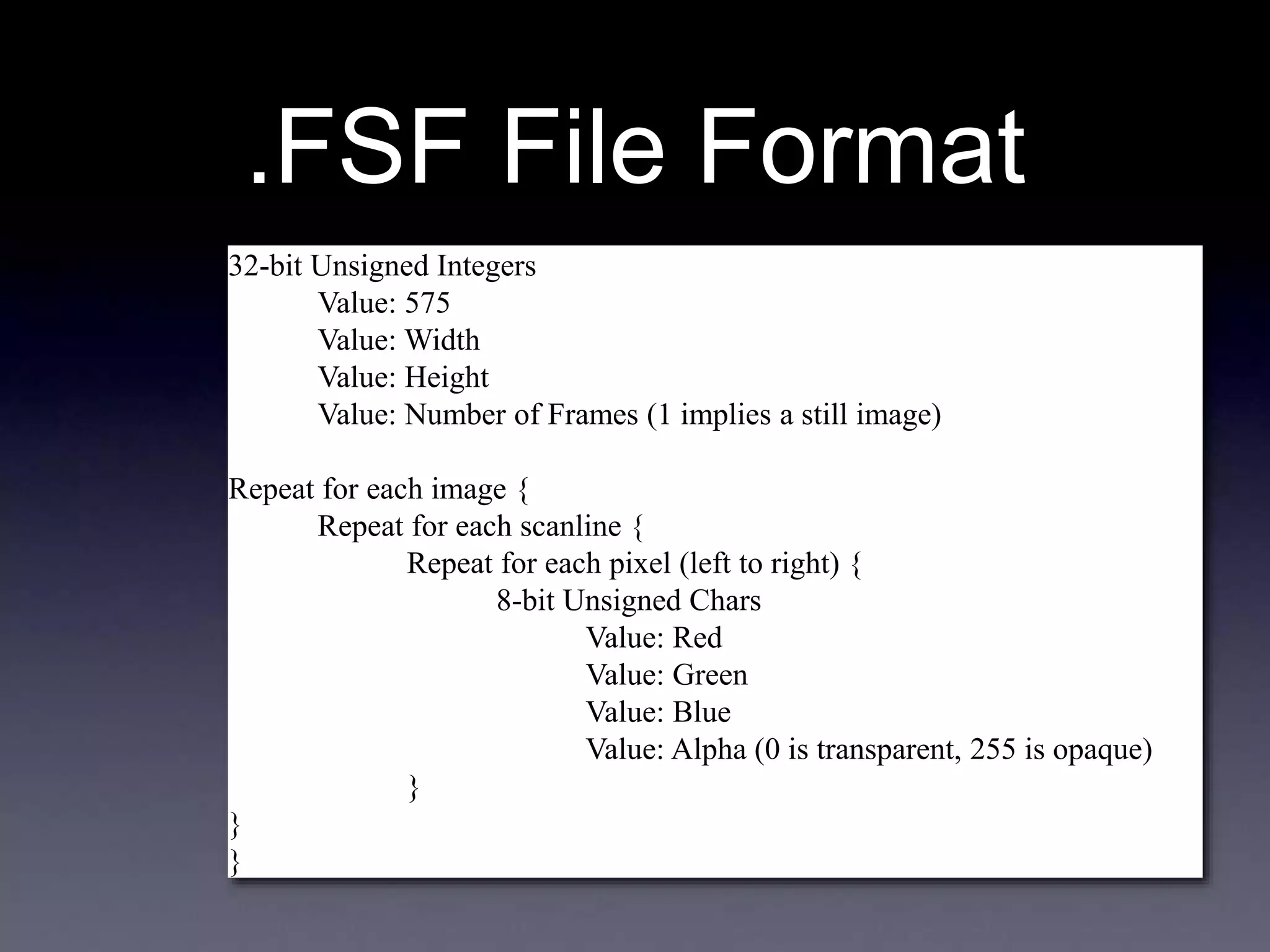
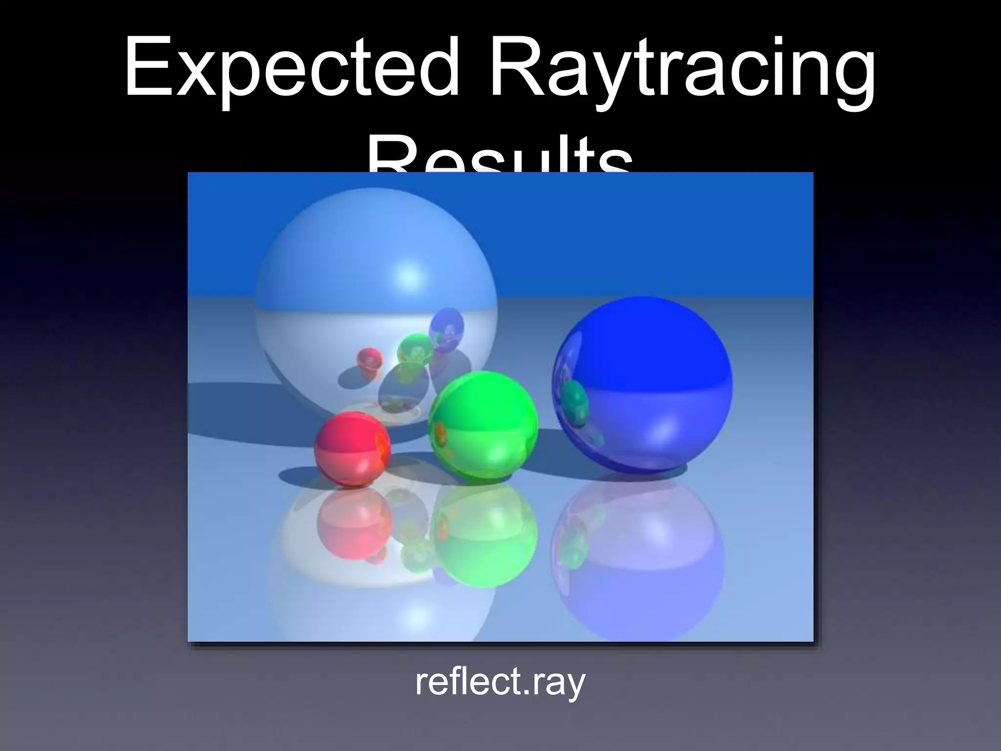
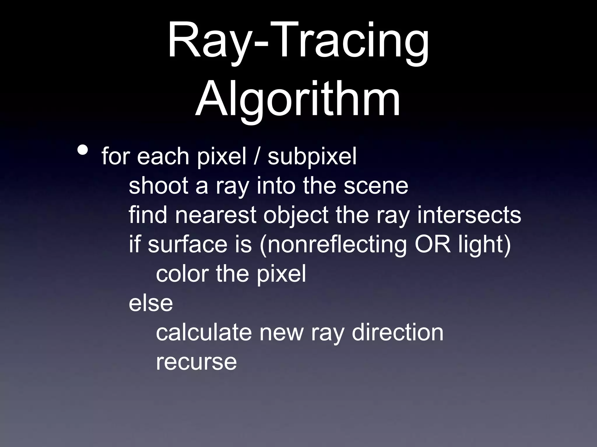
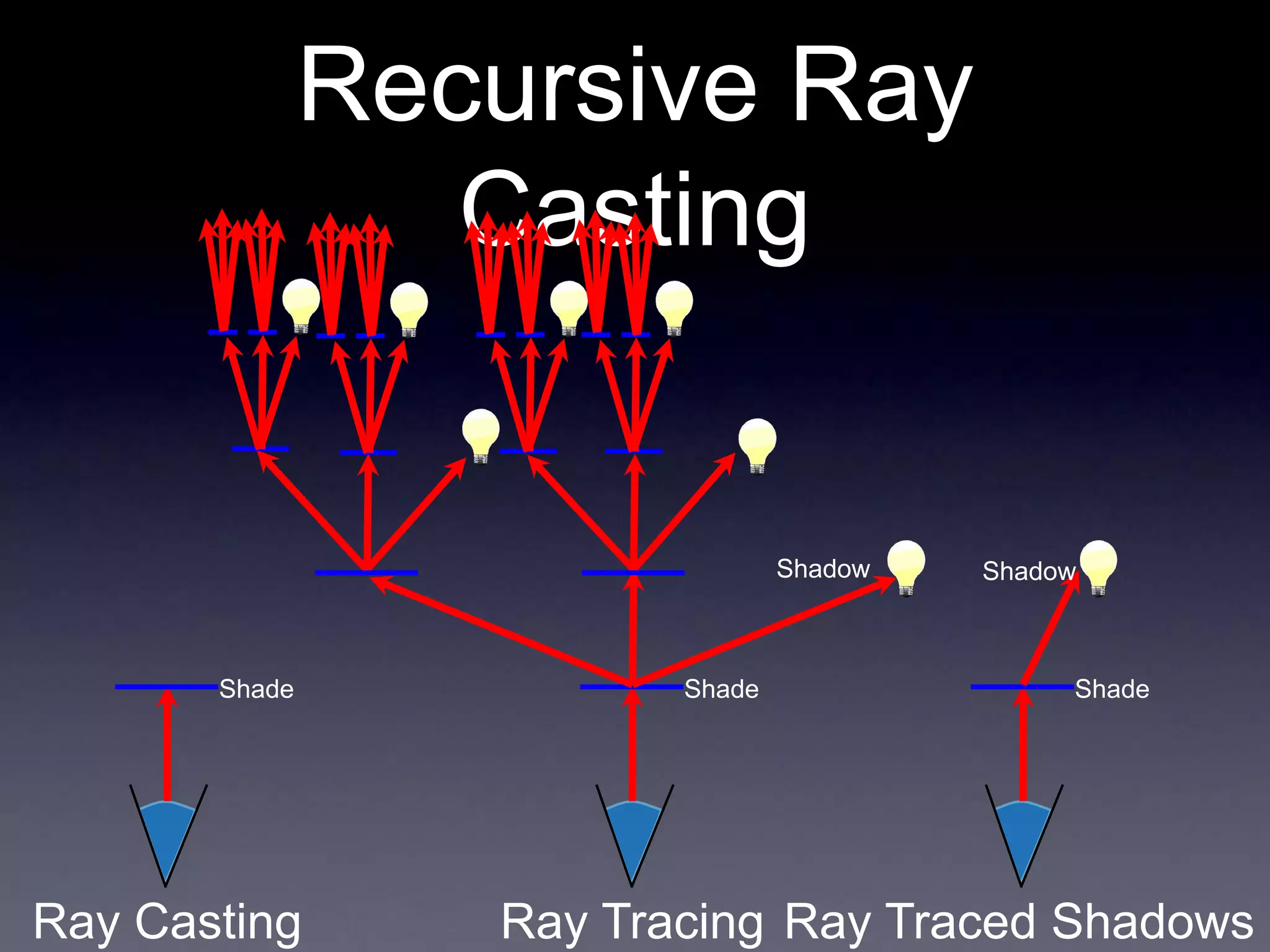
The document contains announcements and instructions for an assignment in a computer graphics course. It discusses file formats for outputting images, implementing ray casting and ray tracing, and transforming objects through translation, rotation and scaling. It also covers generating shadow rays, reflection and refraction. Transforming rays through inverse transforms allows intersecting rays with canonical objects to determine scene intersections.


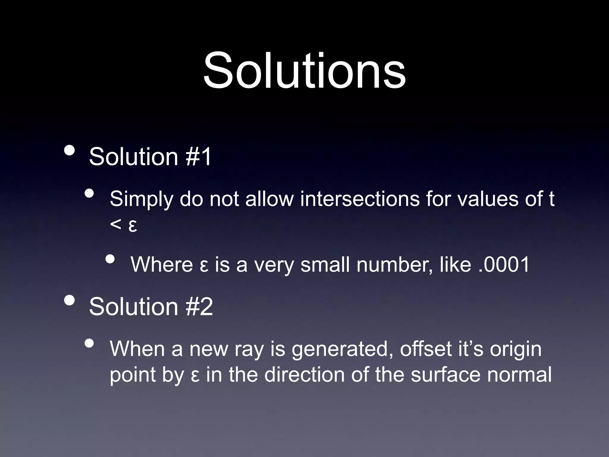
![How to Integrate
This?
• I = (1 - r)Σ[Ia(Ra, La) + Id(n, l, Rd, Ld, a,
b, c, d)
+ Is(r, v, Rs, Ls, n, a, b, c,d)]
• This was our shading equation before:
Ambient
Specular
Diffuse
Lights
• Add another term, say r * (refColor)
• Where r is how reflective the surface is
• [0, 1]
• And refColor is the color from the reflection
ray](https://image.slidesharecdn.com/november6-230404100925-c8a902cf/75/november6-ppt-27-2048.jpg)