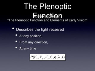
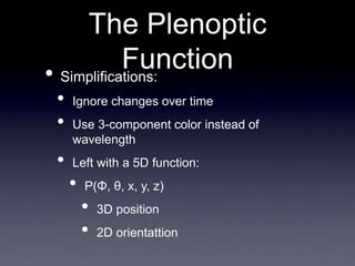
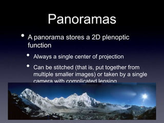
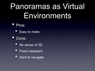
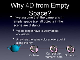
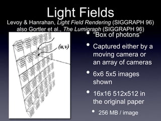
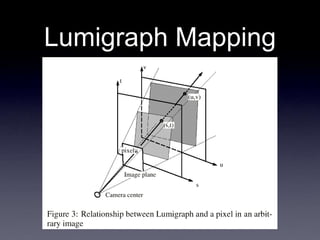
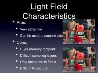
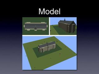
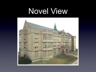
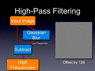
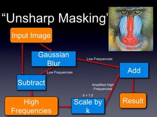
The document provides information about graphics concepts including particle systems, filtering, and computer graphics in video games. It discusses particle systems as a technique for modeling fuzzy effects like fire and smoke using a "cloud" of particles with properties like position, velocity, color, and lifetime. It also covers filtering and convolution for image processing tasks like blurring and sharpening. Finally, it summarizes some of the additional concepts needed for advanced video game development like shaders, physics engines, and game design principles.


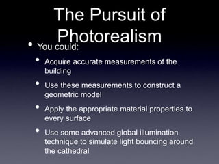
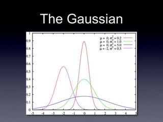
![The Math Behind
Photographs
• Can think of a photograph as a
“catalog” of the colors of the rays that
pass through a single point in space
• i.e. a pinhole, or a camera lens
• We can parametrize any ray
as [Φ, θ, x, y, z]
• The ray through point (x,y,z)
in direction (Φ, θ)](https://image.slidesharecdn.com/november29-230404095940-a54c147a/85/november29-ppt-9-320.jpg)
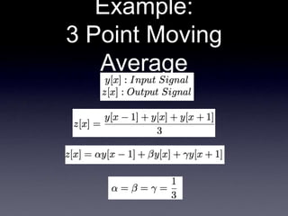
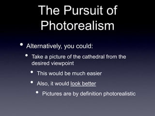
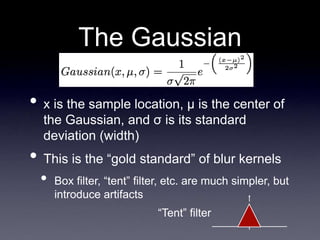
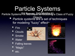
![Example:
3 Point Moving
Average
6 9 12 3 15 3 6
y[x] =
coefficients
=
1/3 1/3 1/3
multiplied by
and sums to
subtotals = 3 4 1
equals
- -
z[x] = ? - - - -
8](https://image.slidesharecdn.com/november29-230404095940-a54c147a/85/november29-ppt-31-320.jpg)
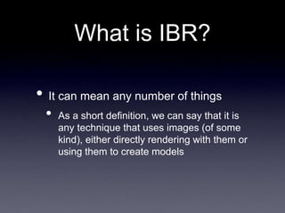
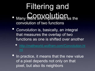
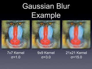
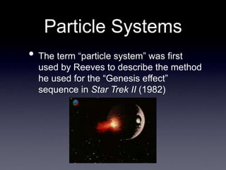
![Example:
3 Point Moving
Average
6 9 12 3 15 3 6
- - 8
y[x] =
z[x] =
coefficients
=
1/3 1/3 1/3
multiplied by
and sums to
subtotals = 4 1 5
equals
10 - - -](https://image.slidesharecdn.com/november29-230404095940-a54c147a/85/november29-ppt-32-320.jpg)
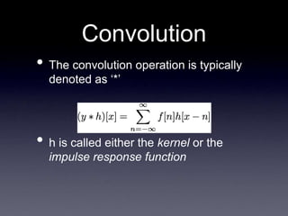
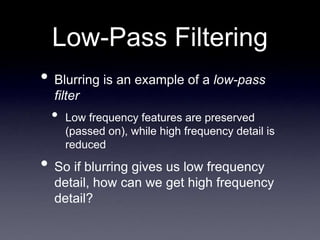
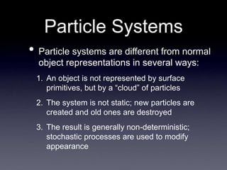
![Example:
3 Point Moving
Average
6 9 12 3 15 3 6
- - 8 10 - - -
y[x] =
z[x] =
coefficients
=
1/3 1/3 1/3
multiplied by
and sums to
subtotals = 1 5 1
equals
7](https://image.slidesharecdn.com/november29-230404095940-a54c147a/85/november29-ppt-33-320.jpg)
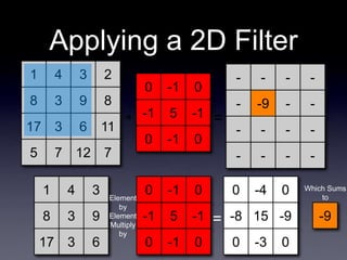
![Example:
3 Point Moving
Average
Kernel = 1/3 1/3 1/3
0 1 2 3 4
-1
-2
-3
-4
1/3
h[x]
“Box Filter”
h[x] = 0 0 1/3 1/3 1/3 0 0
h[0]
h[-1]
h[-2]
h[-3] h[1] h[2] h[3]
...
...
(a.k.a. the Impulse
Response Function)](https://image.slidesharecdn.com/november29-230404095940-a54c147a/85/november29-ppt-34-320.jpg)
![Why “Impulse
Response Function”?
0 1 2 3 4
-1
-2
-3
-4
1/3
h[x]
Kernel
0 1 2 3 4
-1
-2
-3
-4
1/3
f[x] ∗ h[x]
Result
The kernel
models how the
system
responds to an
impulse input
... and any
signal is really
just a set of
impulses of
differing
magnitudes at
different times
0 1 2 3 4
-1
-2
-3
-4
Impulse](https://image.slidesharecdn.com/november29-230404095940-a54c147a/85/november29-ppt-37-320.jpg)


![제 23회 보아즈(BOAZ) 빅데이터 컨퍼런스 - [MBOAX] : ABSA를 활용한 소비자 반응 분석 기반 운영 효율화 대시보드 설계](https://cdn.slidesharecdn.com/ss_thumbnails/3-1boaz23rdconferencemboax-260203102709-9d519923-thumbnail.jpg?width=640&height=640&fit=bounds)


![7.__Developing_a_Research_Proposal[1].pptx](https://cdn.slidesharecdn.com/ss_thumbnails/7-260131073037-df92dd7d-thumbnail.jpg?width=640&height=640&fit=bounds)


