Downloaded 22 times

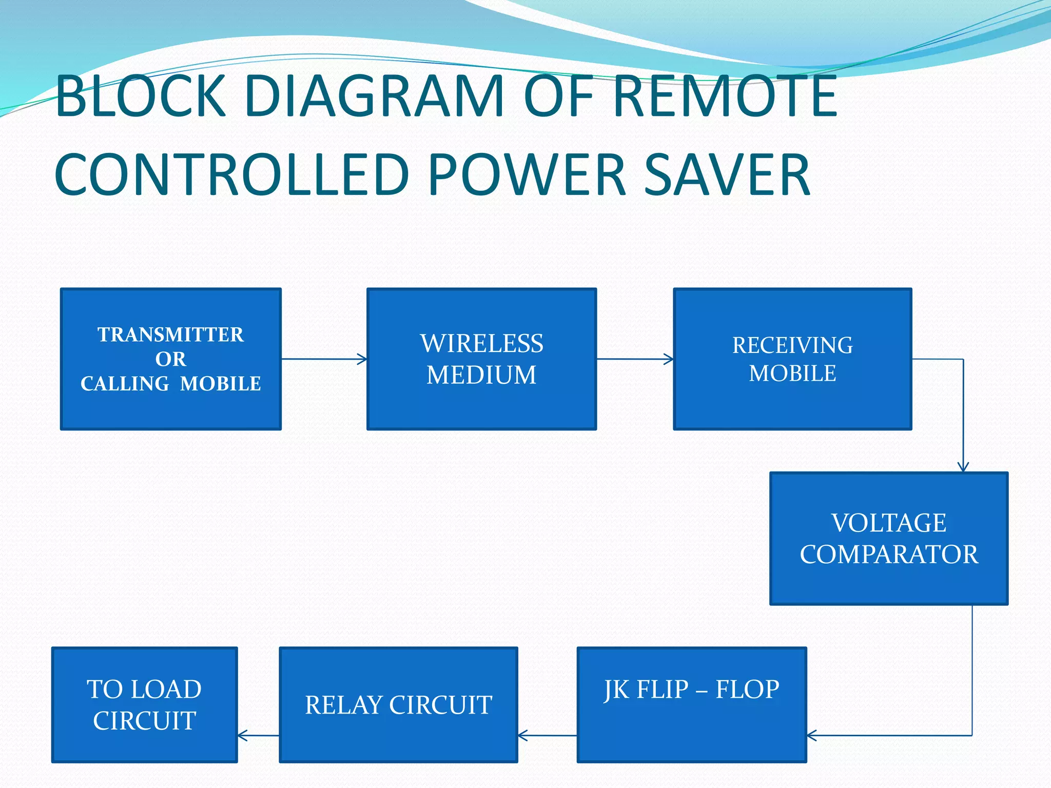
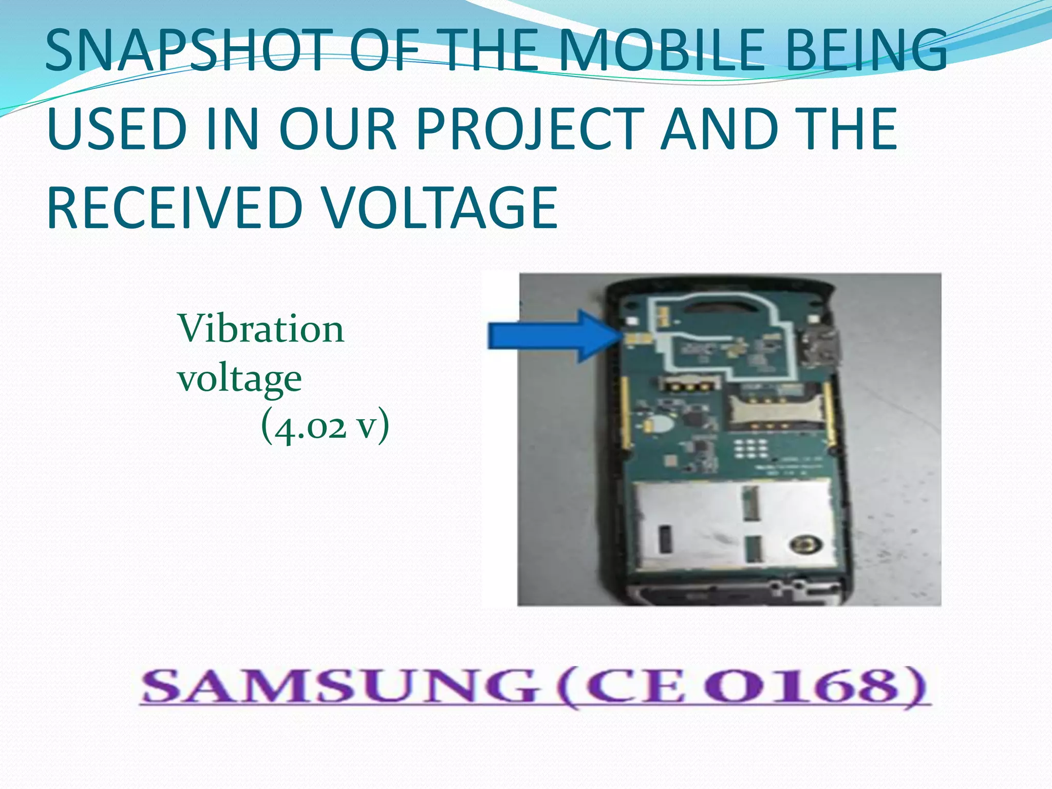
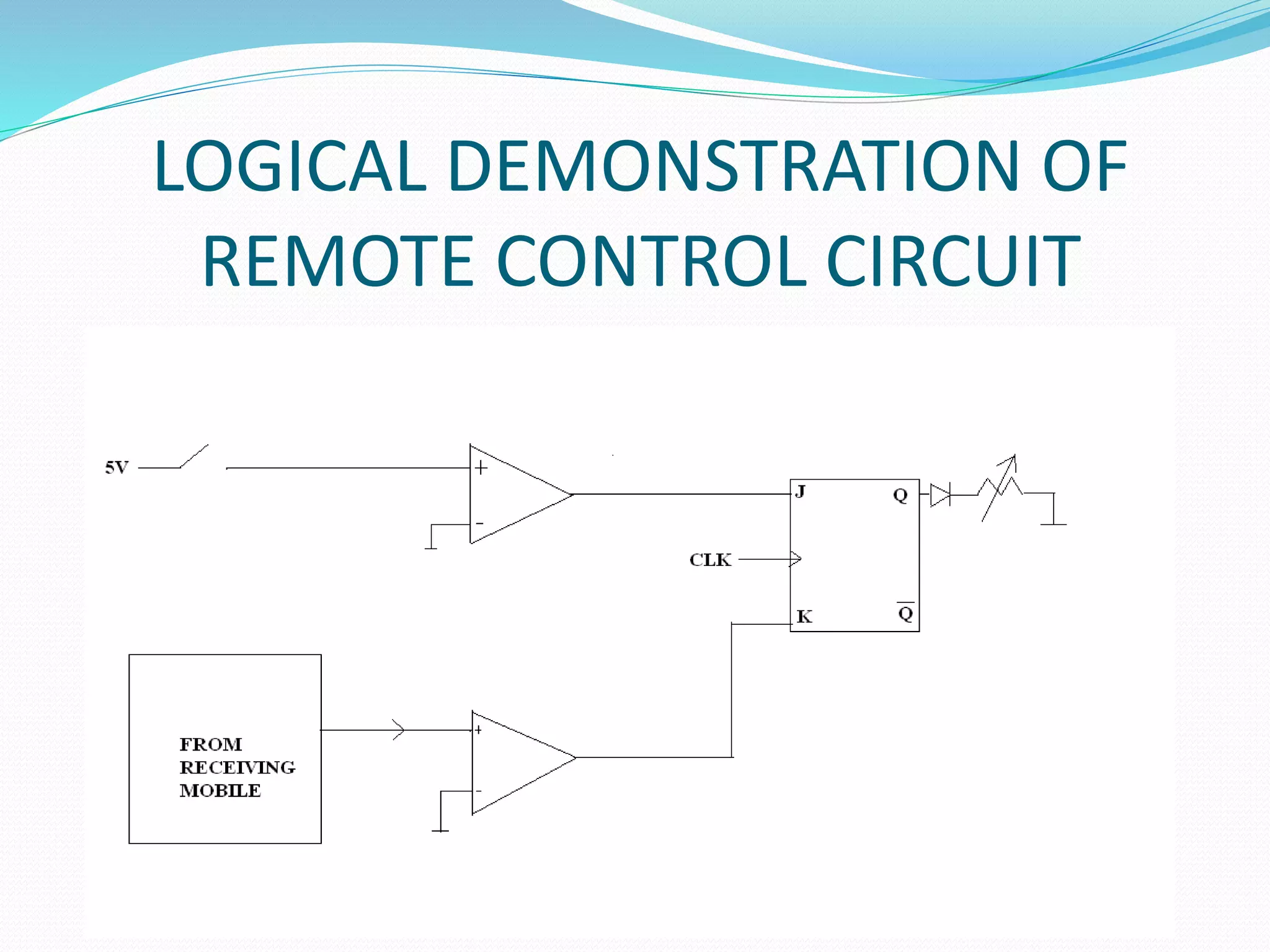

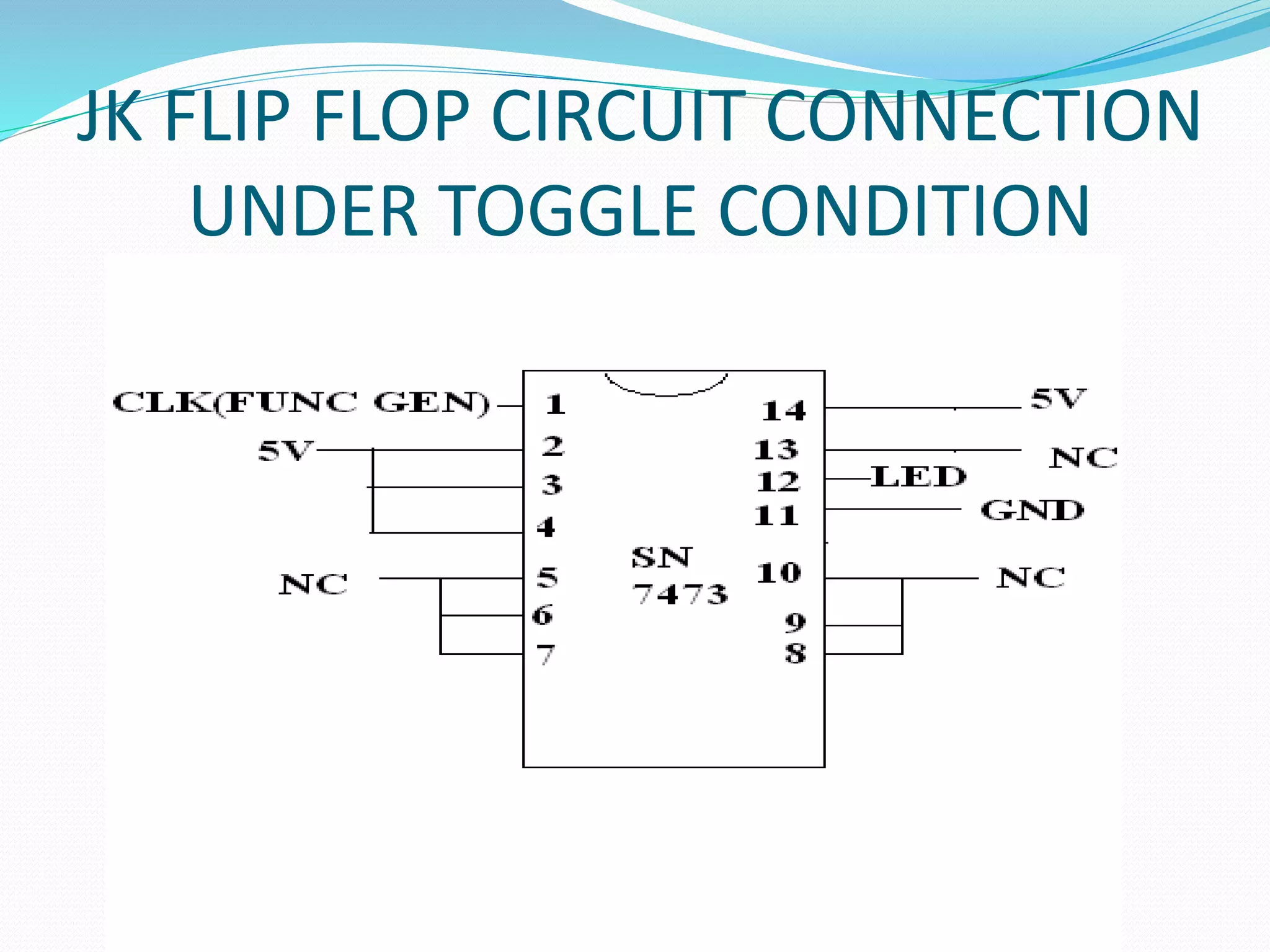


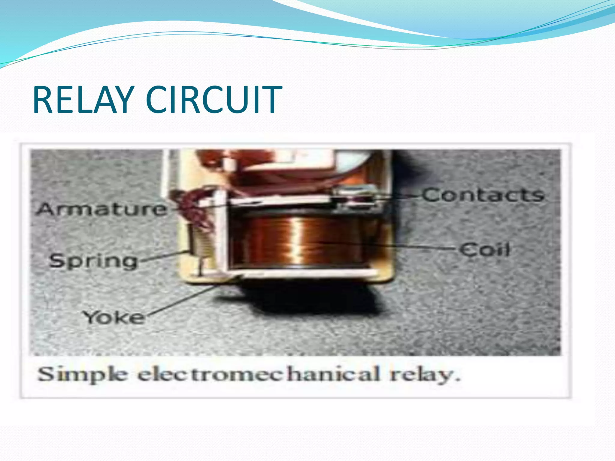
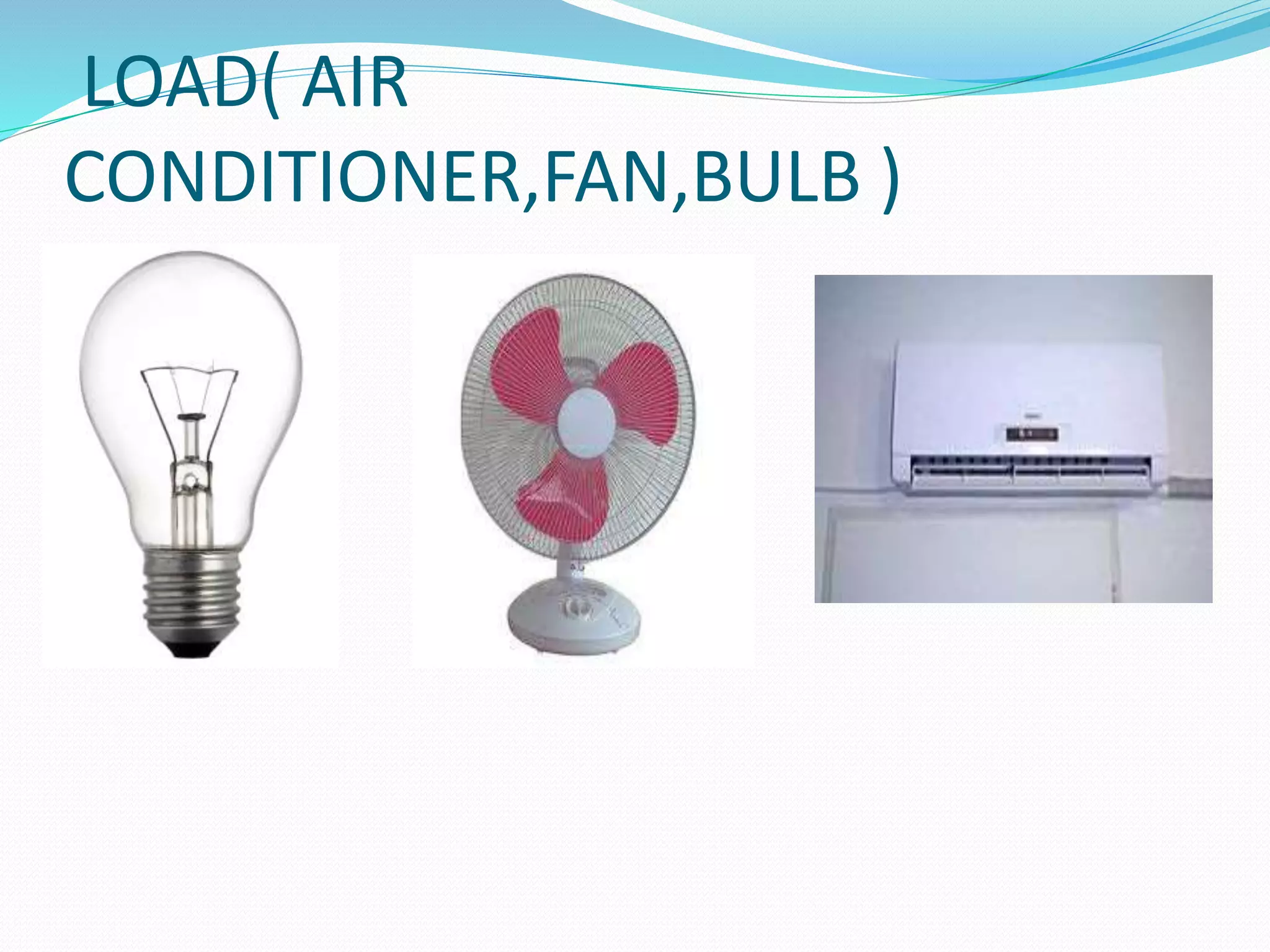
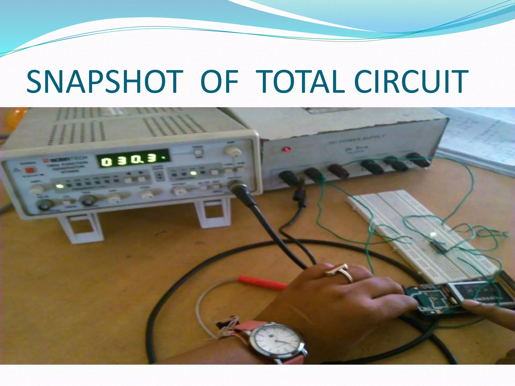


This document describes a remote controlled power saver circuit project submitted by 5 students under the guidance of their professor. It includes block diagrams of the transmitter and receiver circuits which use a mobile phone as the wireless medium. The transmitter circuit uses a JK flip-flop, voltage comparator, and relay circuit to control loads like fans or air conditioners. The receiver circuit obtains a vibration voltage signal from the mobile to drive an astable multivibrator using a 555 timer IC to switch the relay on and off. Future work is proposed to fully construct and test the circuit, analyze signal waveforms, and ensure security of the receiving mobile.