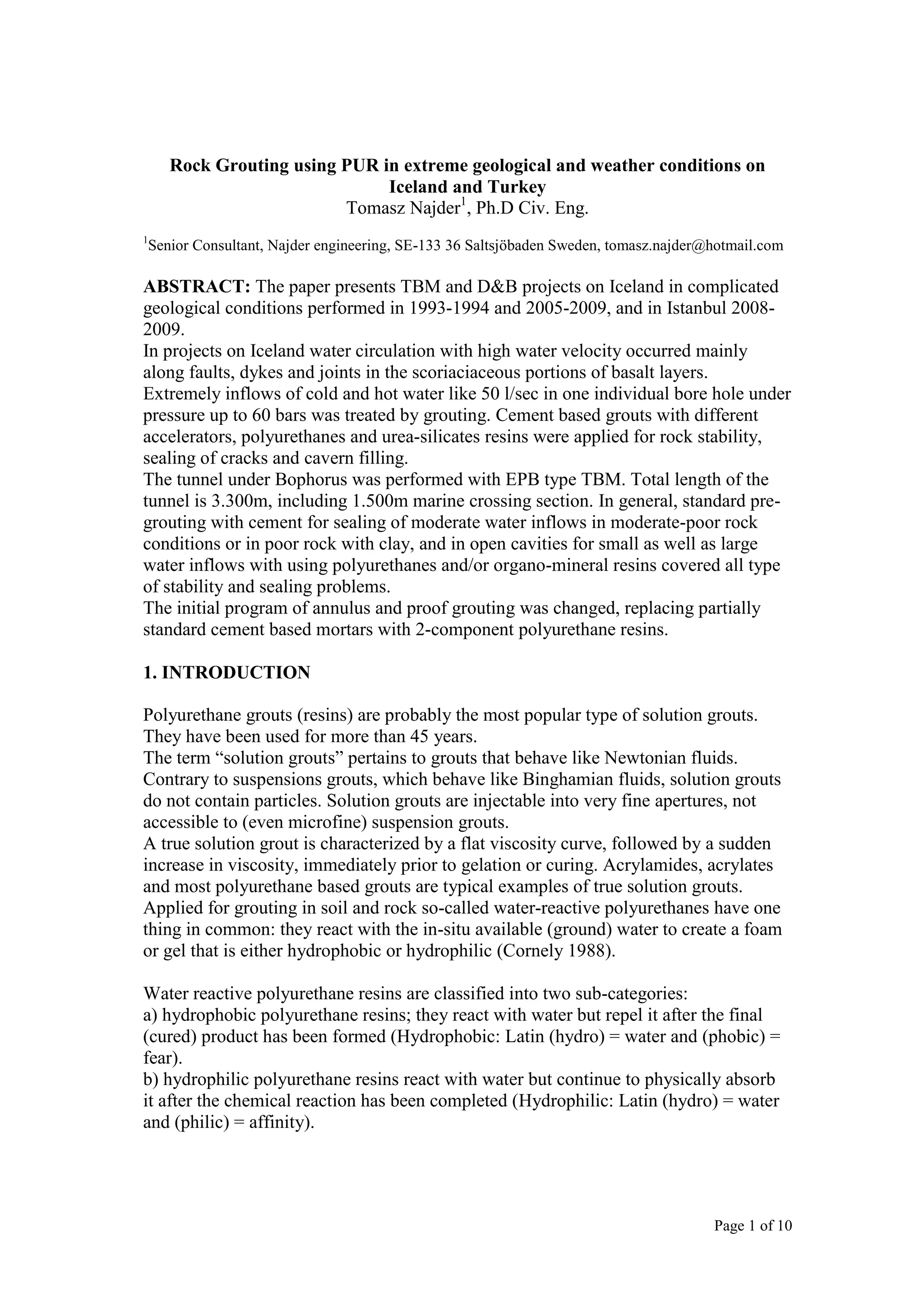
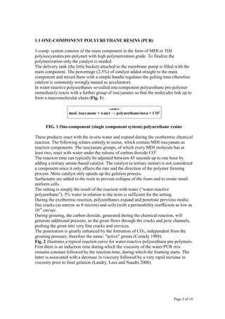
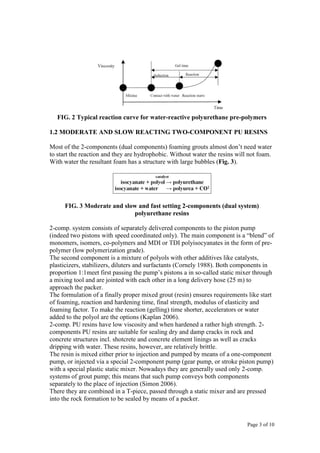
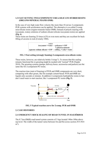
Page 1 of 10
Rock Grouting using PUR in extreme geological and weather conditions on
Iceland and Turkey
Tomasz Najder1
, Ph.D Civ. Eng.
1
Senior Consultant, Najder engineering, SE-133 36 Saltsjöbaden Sweden, tomasz.najder@hotmail.com
ABSTRACT: The paper presents TBM and D&B projects on Iceland in complicated
geological conditions performed in 1993-1994 and 2005-2009, and in Istanbul 2008-
2009.
In projects on Iceland water circulation with high water velocity occurred mainly
along faults, dykes and joints in the scoriaciaceous portions of basalt layers.
Extremely inflows of cold and hot water like 50 l/sec in one individual bore hole under
pressure up to 60 bars was treated by grouting. Cement based grouts with different
accelerators, polyurethanes and urea-silicates resins were applied for rock stability,
sealing of cracks and cavern filling.
The tunnel under Bophorus was performed with EPB type TBM. Total length of the
tunnel is 3.300m, including 1.500m marine crossing section. In general, standard pre-
grouting with cement for sealing of moderate water inflows in moderate-poor rock
conditions or in poor rock with clay, and in open cavities for small as well as large
water inflows with using polyurethanes and/or organo-mineral resins covered all type
of stability and sealing problems.
The initial program of annulus and proof grouting was changed, replacing partially
standard cement based mortars with 2-component polyurethane resins.
1. INTRODUCTION
Polyurethane grouts (resins) are probably the most popular type of solution grouts.
They have been used for more than 45 years.
The term “solution grouts” pertains to grouts that behave like Newtonian fluids.
Contrary to suspensions grouts, which behave like Binghamian fluids, solution grouts
do not contain particles. Solution grouts are injectable into very fine apertures, not
accessible to (even microfine) suspension grouts.
A true solution grout is characterized by a flat viscosity curve, followed by a sudden
increase in viscosity, immediately prior to gelation or curing. Acrylamides, acrylates
and most polyurethane based grouts are typical examples of true solution grouts.
Applied for grouting in soil and rock so-called water-reactive polyurethanes have one
thing in common: they react with the in-situ available (ground) water to create a foam
or gel that is either hydrophobic or hydrophilic (Cornely 1988).
Water reactive polyurethane resins are classified into two sub-categories:
a) hydrophobic polyurethane resins; they react with water but repel it after the final
(cured) product has been formed (Hydrophobic: Latin (hydro) = water and (phobic) =
fear).
b) hydrophilic polyurethane resins react with water but continue to physically absorb
it after the chemical reaction has been completed (Hydrophilic: Latin (hydro) = water
and (philic) = affinity).
Page 2 of 10
1.1 ONE-COMPONENT POLYURETHANE RESINS (PUR)
1-comp. system consists of the main component in the form of MDI or TDI
polyisocyanates pre-polymer with high polymerization grade. To finalize the
polymerization only the catalyst is needed.
The delivery tank (the little bucket) attached to the membrane pump is filled with the
main component. The percentage (2-5%) of catalyst added straight to the main
component and mixed there with a simple handle regulates the gelling time (therefore
catalyst is commonly wrongly named as accelerator).
In water-reactive polyurethanes so-called one-component polyurethane pre-polymer
immediately reacts with a further group of isocyanates so that the molecules link up to
form a macromolecular chain (Fig. 1).
FIG. 1 One-component (single component system) polyurethane resins
These products react with the in-situ water and expand during the exothermic chemical
reaction. The following relates entirely to resins, which contain MDI isocyanate as
reaction components. The isocyanate groups, of which every MDI molecule has at
least two, react with water under the release of carbon dioxide CO2
.
The reaction time can typically be adjusted between 45 seconds up to one hour by
adding a tertiary amine-based catalyst. The catalyst (a tertiary amine) is not considered
a component since it only affects the rate and the direction of the polymer forming
process. More catalyst only speeds up the gelation process.
Surfactants are added to the resin to prevent collapse of the foam and to create small
uniform cells.
The setting is simply the result of the reaction with water (“water-reactive
polyurethane”); 5% water in relation to the resin is sufficient for the setting.
During the exothermic reaction, polyurethanes expand and penetrate pervious media:
fine cracks (as narrow as 8 micron) and soils (with a permeability coefficient as low as
10-4
cm/sec.
During grouting, the carbon dioxide, generated during the chemical reaction, will
generate additional pressure, as the grout flows through the cracks and pore channels,
pushing the grout into very fine cracks and crevices.
The penetration is greatly enhanced by the formation of CO2, independent from the
grouting pressure; therefore the name: "active" grouts (Cornely 1988).
Fig. 2 illustrates a typical reaction curve for water-reactive polyurethane pre-polymers.
First there is an induction time during which the viscosity of the water/PUR mix
remains constant followed by the reaction time, during which the foaming starts. The
latter is associated with a decrease in viscosity followed by a very rapid increase in
viscosity prior to final gelation (Landry, Lees and Naudts 2000).
Page 3 of 10
FIG. 2 Typical reaction curve for water-reactive polyurethane pre-polymers
1.2 MODERATE AND SLOW REACTING TWO-COMPONENT PU RESINS
Most of the 2-components (dual components) foaming grouts almost don’t need water
to start the reaction and they are hydrophobic. Without water the resins will not foam.
With water the resultant foam has a structure with large bubbles (Fig. 3).
FIG. 3 Moderate and slow and fast setting 2-components (dual system)
polyurethane resins
2-comp. system consists of separately delivered components to the piston pump
(indeed two pistons with speed coordinated only). The main component is a “blend” of
monomers, isomers, co-polymers and MDI or TDI polyisocyanates in the form of pre-
polymer (low polymerization grade).
The second component is a mixture of polyols with other additives like catalysts,
plasticizers, stabilizers, diluters and surfactants (Cornely 1988). Both components in
proportion 1:1meet first passing the pump’s pistons a in so-called static mixer through
a mixing tool and are jointed with each other in a long delivery hose (25 m) to
approach the packer.
The formulation of a finally proper mixed grout (resin) ensures requirements like start
of foaming, reaction and hardening time, final strength, modulus of elasticity and
foaming factor. To make the reaction (gelling) time shorter, accelerators or water
added to the polyol are the options (Kaplan 2006).
2-comp. PU resins have low viscosity and when hardened a rather high strength. 2-
components PU resins are suitable for sealing dry and damp cracks in rock and
concrete structures incl. shotcrete and concrete element linings as well as cracks
dripping with water. These resins, however, are relatively brittle.
The resin is mixed either prior to injection and pumped by means of a one-component
pump, or injected via a special 2-component pump (gear pump, or stroke piston pump)
with a special plastic static mixer. Nowadays they are generally used only 2-comp.
systems of grout pump; this means that such pump conveys both components
separately to the place of injection (Simon 2006).
There they are combined in a T-piece, passed through a static mixer and are pressed
into the rock formation to be sealed by means of a packer.
Page 4 of 10
1.3 FAST SETTING TWO-COMPONENT UREA-SILICATE HYBRID RESINS
(ORGANO-MINERAL FOAMS OMR)
In the case of very high water flow velocity like more than 10 cm/sec 2-components
PUR systems with accelerators can be applied. The alternative is so-called 2-comp.
urea-silicate resins (organo-minerals foams OMR). Instead of polyols reacting with
isocyanate, watery solutions of sodium silicate (silicate-isocyanate-resins) are applied
(Fig. 4).
These resins are foaming 25 times (x25) or even more and they are excellent for back-
filling of caverns in rock (Cornely 1988).
FIG. 3 Fast setting (strongly foaming) 2-components urea-silicate resins
These resins, however, are relatively brittle (“crispy”). To ensure that this sealing
remains functional the re-grouting might be needed with “normal” PUR (Najder
2010). The grouting systems (pumps, delivery hoses, accessories and packers) are the
same like for 2-component PU resins.
The reaction time (start of foaming) of PUR and OMR components are very short,
comparing with other grouts, like for example cement based. PUR and OMR are
liquids only seconds or minutes. In addition 2-components hydrophobic resins in fact
don’t need water to start reaction, like 1-component PU resins (Fig. 5).
FIG. 5 Typical reaction curve for 2-comp. PUR and OMR
2. CASE HISTORIES
2.1 EMERGENCY ROCK SEALING OF ROAD TUNNEL IN ISAFJÖRĐUR
The 8.7 km (D&B) road tunnel system consists of 3 legs located 140m-180m above
sea level. The width of the tunnel varies between 5m and 8m (cross section 29.5-50.8
m2
).
Page 5 of 10
The bedrock in the tunnel routes is mainly composed of approximately 13–15 million
years old basaltic layers with sedimentary interbeds. The tunnel is traversing the area
of many fissures and faults as well as several dykes. The rock cover above the tunnel
is ca 600m.
The water leaking into the tunnel was expected lukewarm, even up to +40 ºC warm.
During excavation in single lane Breiđaldalur Tunnel one of the major faults were
intersected and flow rates above 1.000 l/sec occurred. The works were stopped to
enlarge the tunnel section and the ditch for dewatering (Fig. 6).
The excavation started in Botnsheiði Tunnel and stopped at the chainage of 6-10m
from the same strongly leaking fault, intersecting previously avoid huge water inflows
and to increase rock stability. Max water pressure 30-40 bar was measured and water
velocity approx. 6.0 m/sec in the fault (water temperature ca. +20 ºC).
It was obvious that even hardly accelerated cement grouts will be washed out into the
tunnel or moved away and diluted by water running with high velocity in the voids
and cracks perpendicular to the tunnel axis. Therefore one- and 2-comp. PUR were
proposed by the author.
FIG. 6 Water inflows before PUR grouting
Finally after evaluations of obtains results the treatment of the front the decision was
taken to carry out grouting campaign in 2 steps (sequential grouting); decrease the
initial water flow according to descending procedure using 2-component PUR with
extremely short reaction time like start of foaming at 50 sec for +20 ºC and then grout
with a fast reacting cement, accelerated with silicate using fine (approx. 0–0.5 mm)
light-weight sand found at the beach in Bolungarvik located north to the site.
The grout accelerated with CaCl2 showed decantation, separation of sand and
extremely low development concerning stiffness; this grout never was applied.
The grouting holes were drilled first directly inside the face area and then as the
conventional umbrella outside the tunnel profile. The length of primary holes were
8-10m (to the fault), extended finally to 20m. The trial grouting campaign took two
weeks, after that the excavation works were undertaken in Botnsheiði- and later in
Breiðals Tunnel.
Page 6 of 10
The presented grouting procedure were followed in coming disturbed zones with wide
cracks and a high flow of warm and cold water with extremely high pressure.
The project was successfully completed in 1994.
2.2 GROUTING WORKS IN HYDROPOWER KÁRAHNJȖKAR PROJECT
In Kárahnjúkar Hydroelectric Project in eastern Iceland two glacial river systems have
been be dammed and channeled through a series of tunnels into a 690 MW
underground powerhouse.
The Project has a total of 73 km of tunnels; from three access adits, three large
diameters (7.2 m to 7.6 m), main-beam, gripper-type TBMs were used to complete 50-
km headrace tunnel. Partially excavation was performed as conventional D&B.
Using the TBMs was a first in Iceland to excavate the complex Icelandic basalt
formations, which consist of inclined layers of hard basaltic flows with weaker
scoriaceous and sedimentary interbeds.
Fault zones (typically 0.5-2m wide) and faults with thickness exceeding 10m,
(characterized by sheared, crushed rock, with grain size distribution ranging from
blocks down to clay) posed both geologic and hydrogeologic difficulties to the TBM
and D&B tunnelling. In some faults, the coarse grained crushed material was well
cemented by fines, whereas in others the crushed material was weathered and loose.
The joints, fissures and faults provided a major pathway for ground water seepage,
along with the contact zones of the geological strata, and gave rise to the risk of
potentially high and sudden water inflow during excavation.
The water table close to surface level resulted in hydraulic pressures of potentially 20
bars at tunnel horizon with infinite recharges from the various streams and lakes in the
project area.
The seasonal melting of the glacier was expected to result in a time-dependent
variation of the natural water table and potentially variable inflows into the tunnel over
time.
The serious incidents showed clearly that continuous probe drilling and sampling or
rotary-percussive drilling were required in the expected fault zones, as well as
umbrella pre grouting. To decrease the interruptions time in excavation and due to
wash-out effect of cement grouts in heavy leaking chainages, the option with 2-comp.
PUR, instead of conventional cement mixes was proposed and commonly used. For
filling cavities urea-silicate foams was the option instead of ordinary concrete or
shotcrete.
The contractor preferred high progress of excavation and the fundamental demand of
necessity of grouting in the case of one drill hole leaking more than 5 l/sec or 7 l/sec in
two holes in combination was not always followed. The pre grouting operations had
not always been succeeded or properly executed. More and more strongly leaking
faults (like individual up to 100-150 l/sec) were left to complete as post grouting
during finishing works.
Post grouting, even performed in proper way, was always several times more time
consuming and expensive due to larger grout volume required to get rock consolidated
(Fig. 7).
Page 7 of 10
FIG. 7 Water inflows before starting post grouting with 2-comp. PUR and OMR
Polyurethanes used by the contractor had fundamental reactivity problems in cold
water in the tunnel. To avoid any potential risk of ground water pollution these resins
were replaced by the similar products used in Ísafjörður. Crispy and not durable urea-
silicate resins from the same PUR producer proposed by the contractor (applied to
cavity re-filling) were replaced by other products for the same safety reason.
Low rock and water temperature under +3 ºC almost around a year decreased the
usage of cement mixes practically to minimum. Majority of post grouting campaigns
were performed using PUR and OMR.
The project was completed in 2008.
2.3 GROUTING IN HÉDINSFJÖRDURGONG
Vegagerðin (Public Road Administration) constructed in 2007-2010 two D&B tunnels
in northern Iceland at a total length of almost 11 km. These tunnels between the towns
of Siglufjörður and Ólafsfjörður on the north coast are the part of a new segment of the
Island’s main arterial road. The shorter one, Siglufjörður Tunnel, is 3.871m long, and
the other one, Ólafsfjörður Tunnel, is 7.124m long (Stehlik, Hardarson 2009).
Both tunnels are of the same profile, which is 52.83 m2
(in regularly intervals 75.25
m2
, serving as lay-bys for vehicle emergency parking). The design and specifications
were based on Norwegian regulations and experience, commonly named as
“Scandinavian Method” with the maximum length of round (5m) and with minimum
support measures like shotcrete only and in bad parts of rock with shotcrete and
bolting.
For Siglufjörður Tunnel dominating rock is basalt with sub-horizontal bedding, with
changing porosity. During the excavation the sedimentary tuff layer was identified. In
Ólafsfjörður Tunnel the excavation was performed in volcanic tertiary rocks, mostly
basalts and partially volcano-clastic. The basalts were fine to medium grained.
Volcano-clastic sediments were represented by scoria and red sandstone. The rock
cover thickness was relatively high, up to 600m in the section under the Hólsfjall peak
the rest of previous 28 million old volcano 5.000m high.
Within first 2 km the water inflows into the tunnel were not significant with low
impact on the excavation itself. Very soon the water ingress started to be higher;
Page 8 of 10
finally the water inflow reached more than 2000 l/min (Fig. 8).
All pre grouting efforts using cementitious mixes were none effective due to high
water pressure and very low water temperature under +3 ºC (in May –June).
Just at the start of excavation Ólafsfjörður Tunnel 3 probe holes were grouted as
instructed by the supervision. Due to the high water pressure and therefore not deep
enough inserted packers (only short mechanical packers available) grouting was not
successful. Next attempt was again not successful, because the available packers were
during the grouting process pushed out of the holes by high water pressure. The water
pressure was measured to be 15 bars (in some further sections even 25-35 bars).
Apart of problems with packers, the cement grouting would not succeed under the
given conditions, mainly due to the low water temperature (+2 ºC÷ +4 ºC).
In the pre grouting case with complete umbrella min 18-24 grouting holes ø = 51 mm
were applied instead of ø = 63 mm; mechanical packers were replaced by inflatable,
disposable packers. For extremely high pressure sets of 2 or 3 inflatable packers to get
better bond were proposed and implemented.
The contractor was instructed not to come closer than 6-8m from the faults, on the
other hand packers could not be placed more than 3-4m from the face due to high
water pressure (locally 50-60 bars) or collapsing unstable rock around borehole.
FIG. 8 Water inflows during tunnel excavation
Like in Kárahnjúkar Hydropower Project, very low rock and water temperature under
+3 ºC almost around a year decreased the usage of previously recommended cement
mixes. Majority of post grouting campaigns were performed using PU.
The excavation and grouting were completed in March 2009 (Cyroň, Kučera 2009).
2.4 GROUTING ACTIVITIES IN THE GREAT MELEN PROJECT IN
ISTANBUL
The Bosphorus Tunnel is to provide the connection between Asia and Europe across
the Bosphorus channel enabling the water from the Melen River to be transferred to
Istanbul. The tunnel is approximately 5.6 km in length and is located ca. 15 km to the
north of Istanbul.
The European incline and underwater sections were excavated by a fully shielded
Page 9 of 10
closed (or open) mode Earth Pressure Balance Type TBM (shield 6.120 mm
diameter).
The TBM tunnel with excavation and segment lining, commenced in February 2008,
finished in May 2009 (the first tunnel between two continents).
The early average temperature is +13.6 °C. The average lowest soil temperature at
the ground surface is +9.1 °C.
The detailed Method Statement for different types of grouting and scenario was
worked out before starting excavation under water level. In general, standard pre
grouting with OP cement for sealing of moderate water inflows in moderate-poor
rock conditions or in poor rock with clay, and in open cavities for small as well as
large water inflows with using polyurethanes and/or urea-silicate foams covered all
type of stability and sealing problems.
TBM allowed performing probe drilling and drilling for grouting through cutter head
with almost horizontal holes or optionally in conventional umbrella.
The initial program of annulus grouting (to fill the void between a precast concrete
segmental lining and the surrounding rock) and proof grouting was changed,
replacing partially standard cement based mortars with 2-comp. PUR.
Cut-off membranes was performed after annulus- and proof grouting to prevent rest-
water ingress along the lining to the cutter head compartment in the inclined section
of the tunnel (Velez 2008). This grouting was executed with 2-comp. PUR, not any
longer with cement slurry or mortars as planned.
FIG. 8 PUR grouting for cut-off membranes and lining repairs
The importance of regularly cut-off membranes was due to water-rest flow to the
cutter head section, making impossible (even with small water inflow) mucking of
rock cuttings and hampering TBM loading system. Due to the fact that the tunnel is
falling down at a gradient of approximately 7.439% to the lowest tunnel section
under the Bosphorus Channel, none treated rest-water gradually increased.
Cut-off membranes performed with urea-silicate foams decreased the time of TBM
stoppage and the risk of “gluing” of cutter head comparing with cementitious grouts.
2-comp. PUR was very effectively used in cracks sealing within concrete lining and
sealing of leaking gaskets.
Page 10 of 10
3.0 FINAL COMMENTS
- In general cement based grouts remain the material of first choice for pressure
grouting in tunnelling. This is due to their low cost, availability, well documented
properties, experience and environmental acceptability.
- The wide range of available none toxic chemical grouts and resins offer today a
useful supplement to cement grouts, especially when tightness requirements are strict.
Chemical grouts and resins can penetrate and seal cracks and very fine fissures that
cement grouts will not enter. Even in hard rock formations like olivine basalt on
Iceland high number of water bearing small cracks may in total produce substantial
leakage.
- The significant problem for successful grouting is often the wide variety of joint
filling materials like silt and clay that can be found. Such joint fillings tend to inhibit
cement based grouts penetration and distribution. Very fine fill materials (often
unstable under high water pressure) are both partially penetrated, squeezed around by
the proper chosen polyurethane (PU) resins and dried due to decreasing of water
content in clay taken to reaction of polyurethanes basic component- polyisocyanates.
Such fills are not available even for ultra fine cements, silica fume and silica sol.
- Especial useless cement grouts are in the case of large caverns and cavities open or
empty due to wash-out effect of material from mentioned above wide faults and
joints. The urea-silicate foams due to extremely high foaming factor like x = 30-40
are irreplaceable for such stabilization and refilling of cavities in the tunnels. Thanks
their expansion the decrease of total grout consumption and shorter time of execution
compensate relative much cost of grout per m3
compared with cement material.
- Polyurethanes and urea-silicate resins showed their excellent abilities in grouting in
“normal” and extreme tunnelling conditions. These materials allowed safer and faster
excavation, finally decreasing total tunnelling costs comparing with traditional
grouting with cement suspensions.
4.0 REFERENCES
Cornely, W. (1988). “Polyurethane Grouts for Waterstop in Tunnels and Tunnelling”,
Int. Congress on Tunnels and Water, Madrid: 413-418.
Cyroň, D., Kučera P. (2009). “Iceland - Sealing water in lafsjördur and Siglufhördur
road tunnel excavation”. Company Bulletin – Metrostav a.s., Minova Bohemia
s.r.o.
Kaplan, Philip. (2006). Personal communications (Minova CarboTech).
Landry, E., Lees, D., and Naudts, A. (2000). "New Developments in Rock and Soil
Grouting: Design and Evaluation." Geotechnical News. September 2000: 38-44.
Najder, T. (2010). “Polyuretanresiner (harts) i berginjektering och tunnelreparationer”.
Kursdagene 2010 Berginjeksjon i praksis, Trondheim.
Simon, Peter. (2006). Personal communications (Minova CarboTech).
Stehlik, E., Hardarson, B. (2009). “An Icelandic struggle.” Tunnels & Tunnelling
International.
Velez, Diego. (2008). Personal communications (Minova CarboTech).
Page 11 of 10

ö New Orleans 2012 draft paper 2011.01.27

  • 1.
    Page 1 of10 Rock Grouting using PUR in extreme geological and weather conditions on Iceland and Turkey Tomasz Najder1 , Ph.D Civ. Eng. 1 Senior Consultant, Najder engineering, SE-133 36 Saltsjöbaden Sweden, tomasz.najder@hotmail.com ABSTRACT: The paper presents TBM and D&B projects on Iceland in complicated geological conditions performed in 1993-1994 and 2005-2009, and in Istanbul 2008- 2009. In projects on Iceland water circulation with high water velocity occurred mainly along faults, dykes and joints in the scoriaciaceous portions of basalt layers. Extremely inflows of cold and hot water like 50 l/sec in one individual bore hole under pressure up to 60 bars was treated by grouting. Cement based grouts with different accelerators, polyurethanes and urea-silicates resins were applied for rock stability, sealing of cracks and cavern filling. The tunnel under Bophorus was performed with EPB type TBM. Total length of the tunnel is 3.300m, including 1.500m marine crossing section. In general, standard pre- grouting with cement for sealing of moderate water inflows in moderate-poor rock conditions or in poor rock with clay, and in open cavities for small as well as large water inflows with using polyurethanes and/or organo-mineral resins covered all type of stability and sealing problems. The initial program of annulus and proof grouting was changed, replacing partially standard cement based mortars with 2-component polyurethane resins. 1. INTRODUCTION Polyurethane grouts (resins) are probably the most popular type of solution grouts. They have been used for more than 45 years. The term “solution grouts” pertains to grouts that behave like Newtonian fluids. Contrary to suspensions grouts, which behave like Binghamian fluids, solution grouts do not contain particles. Solution grouts are injectable into very fine apertures, not accessible to (even microfine) suspension grouts. A true solution grout is characterized by a flat viscosity curve, followed by a sudden increase in viscosity, immediately prior to gelation or curing. Acrylamides, acrylates and most polyurethane based grouts are typical examples of true solution grouts. Applied for grouting in soil and rock so-called water-reactive polyurethanes have one thing in common: they react with the in-situ available (ground) water to create a foam or gel that is either hydrophobic or hydrophilic (Cornely 1988). Water reactive polyurethane resins are classified into two sub-categories: a) hydrophobic polyurethane resins; they react with water but repel it after the final (cured) product has been formed (Hydrophobic: Latin (hydro) = water and (phobic) = fear). b) hydrophilic polyurethane resins react with water but continue to physically absorb it after the chemical reaction has been completed (Hydrophilic: Latin (hydro) = water and (philic) = affinity).
  • 2.
    Page 2 of10 1.1 ONE-COMPONENT POLYURETHANE RESINS (PUR) 1-comp. system consists of the main component in the form of MDI or TDI polyisocyanates pre-polymer with high polymerization grade. To finalize the polymerization only the catalyst is needed. The delivery tank (the little bucket) attached to the membrane pump is filled with the main component. The percentage (2-5%) of catalyst added straight to the main component and mixed there with a simple handle regulates the gelling time (therefore catalyst is commonly wrongly named as accelerator). In water-reactive polyurethanes so-called one-component polyurethane pre-polymer immediately reacts with a further group of isocyanates so that the molecules link up to form a macromolecular chain (Fig. 1). FIG. 1 One-component (single component system) polyurethane resins These products react with the in-situ water and expand during the exothermic chemical reaction. The following relates entirely to resins, which contain MDI isocyanate as reaction components. The isocyanate groups, of which every MDI molecule has at least two, react with water under the release of carbon dioxide CO2 . The reaction time can typically be adjusted between 45 seconds up to one hour by adding a tertiary amine-based catalyst. The catalyst (a tertiary amine) is not considered a component since it only affects the rate and the direction of the polymer forming process. More catalyst only speeds up the gelation process. Surfactants are added to the resin to prevent collapse of the foam and to create small uniform cells. The setting is simply the result of the reaction with water (“water-reactive polyurethane”); 5% water in relation to the resin is sufficient for the setting. During the exothermic reaction, polyurethanes expand and penetrate pervious media: fine cracks (as narrow as 8 micron) and soils (with a permeability coefficient as low as 10-4 cm/sec. During grouting, the carbon dioxide, generated during the chemical reaction, will generate additional pressure, as the grout flows through the cracks and pore channels, pushing the grout into very fine cracks and crevices. The penetration is greatly enhanced by the formation of CO2, independent from the grouting pressure; therefore the name: "active" grouts (Cornely 1988). Fig. 2 illustrates a typical reaction curve for water-reactive polyurethane pre-polymers. First there is an induction time during which the viscosity of the water/PUR mix remains constant followed by the reaction time, during which the foaming starts. The latter is associated with a decrease in viscosity followed by a very rapid increase in viscosity prior to final gelation (Landry, Lees and Naudts 2000).
  • 3.
    Page 3 of10 FIG. 2 Typical reaction curve for water-reactive polyurethane pre-polymers 1.2 MODERATE AND SLOW REACTING TWO-COMPONENT PU RESINS Most of the 2-components (dual components) foaming grouts almost don’t need water to start the reaction and they are hydrophobic. Without water the resins will not foam. With water the resultant foam has a structure with large bubbles (Fig. 3). FIG. 3 Moderate and slow and fast setting 2-components (dual system) polyurethane resins 2-comp. system consists of separately delivered components to the piston pump (indeed two pistons with speed coordinated only). The main component is a “blend” of monomers, isomers, co-polymers and MDI or TDI polyisocyanates in the form of pre- polymer (low polymerization grade). The second component is a mixture of polyols with other additives like catalysts, plasticizers, stabilizers, diluters and surfactants (Cornely 1988). Both components in proportion 1:1meet first passing the pump’s pistons a in so-called static mixer through a mixing tool and are jointed with each other in a long delivery hose (25 m) to approach the packer. The formulation of a finally proper mixed grout (resin) ensures requirements like start of foaming, reaction and hardening time, final strength, modulus of elasticity and foaming factor. To make the reaction (gelling) time shorter, accelerators or water added to the polyol are the options (Kaplan 2006). 2-comp. PU resins have low viscosity and when hardened a rather high strength. 2- components PU resins are suitable for sealing dry and damp cracks in rock and concrete structures incl. shotcrete and concrete element linings as well as cracks dripping with water. These resins, however, are relatively brittle. The resin is mixed either prior to injection and pumped by means of a one-component pump, or injected via a special 2-component pump (gear pump, or stroke piston pump) with a special plastic static mixer. Nowadays they are generally used only 2-comp. systems of grout pump; this means that such pump conveys both components separately to the place of injection (Simon 2006). There they are combined in a T-piece, passed through a static mixer and are pressed into the rock formation to be sealed by means of a packer.
  • 4.
    Page 4 of10 1.3 FAST SETTING TWO-COMPONENT UREA-SILICATE HYBRID RESINS (ORGANO-MINERAL FOAMS OMR) In the case of very high water flow velocity like more than 10 cm/sec 2-components PUR systems with accelerators can be applied. The alternative is so-called 2-comp. urea-silicate resins (organo-minerals foams OMR). Instead of polyols reacting with isocyanate, watery solutions of sodium silicate (silicate-isocyanate-resins) are applied (Fig. 4). These resins are foaming 25 times (x25) or even more and they are excellent for back- filling of caverns in rock (Cornely 1988). FIG. 3 Fast setting (strongly foaming) 2-components urea-silicate resins These resins, however, are relatively brittle (“crispy”). To ensure that this sealing remains functional the re-grouting might be needed with “normal” PUR (Najder 2010). The grouting systems (pumps, delivery hoses, accessories and packers) are the same like for 2-component PU resins. The reaction time (start of foaming) of PUR and OMR components are very short, comparing with other grouts, like for example cement based. PUR and OMR are liquids only seconds or minutes. In addition 2-components hydrophobic resins in fact don’t need water to start reaction, like 1-component PU resins (Fig. 5). FIG. 5 Typical reaction curve for 2-comp. PUR and OMR 2. CASE HISTORIES 2.1 EMERGENCY ROCK SEALING OF ROAD TUNNEL IN ISAFJÖRĐUR The 8.7 km (D&B) road tunnel system consists of 3 legs located 140m-180m above sea level. The width of the tunnel varies between 5m and 8m (cross section 29.5-50.8 m2 ).
  • 5.
    Page 5 of10 The bedrock in the tunnel routes is mainly composed of approximately 13–15 million years old basaltic layers with sedimentary interbeds. The tunnel is traversing the area of many fissures and faults as well as several dykes. The rock cover above the tunnel is ca 600m. The water leaking into the tunnel was expected lukewarm, even up to +40 ºC warm. During excavation in single lane Breiđaldalur Tunnel one of the major faults were intersected and flow rates above 1.000 l/sec occurred. The works were stopped to enlarge the tunnel section and the ditch for dewatering (Fig. 6). The excavation started in Botnsheiði Tunnel and stopped at the chainage of 6-10m from the same strongly leaking fault, intersecting previously avoid huge water inflows and to increase rock stability. Max water pressure 30-40 bar was measured and water velocity approx. 6.0 m/sec in the fault (water temperature ca. +20 ºC). It was obvious that even hardly accelerated cement grouts will be washed out into the tunnel or moved away and diluted by water running with high velocity in the voids and cracks perpendicular to the tunnel axis. Therefore one- and 2-comp. PUR were proposed by the author. FIG. 6 Water inflows before PUR grouting Finally after evaluations of obtains results the treatment of the front the decision was taken to carry out grouting campaign in 2 steps (sequential grouting); decrease the initial water flow according to descending procedure using 2-component PUR with extremely short reaction time like start of foaming at 50 sec for +20 ºC and then grout with a fast reacting cement, accelerated with silicate using fine (approx. 0–0.5 mm) light-weight sand found at the beach in Bolungarvik located north to the site. The grout accelerated with CaCl2 showed decantation, separation of sand and extremely low development concerning stiffness; this grout never was applied. The grouting holes were drilled first directly inside the face area and then as the conventional umbrella outside the tunnel profile. The length of primary holes were 8-10m (to the fault), extended finally to 20m. The trial grouting campaign took two weeks, after that the excavation works were undertaken in Botnsheiði- and later in Breiðals Tunnel.
  • 6.
    Page 6 of10 The presented grouting procedure were followed in coming disturbed zones with wide cracks and a high flow of warm and cold water with extremely high pressure. The project was successfully completed in 1994. 2.2 GROUTING WORKS IN HYDROPOWER KÁRAHNJȖKAR PROJECT In Kárahnjúkar Hydroelectric Project in eastern Iceland two glacial river systems have been be dammed and channeled through a series of tunnels into a 690 MW underground powerhouse. The Project has a total of 73 km of tunnels; from three access adits, three large diameters (7.2 m to 7.6 m), main-beam, gripper-type TBMs were used to complete 50- km headrace tunnel. Partially excavation was performed as conventional D&B. Using the TBMs was a first in Iceland to excavate the complex Icelandic basalt formations, which consist of inclined layers of hard basaltic flows with weaker scoriaceous and sedimentary interbeds. Fault zones (typically 0.5-2m wide) and faults with thickness exceeding 10m, (characterized by sheared, crushed rock, with grain size distribution ranging from blocks down to clay) posed both geologic and hydrogeologic difficulties to the TBM and D&B tunnelling. In some faults, the coarse grained crushed material was well cemented by fines, whereas in others the crushed material was weathered and loose. The joints, fissures and faults provided a major pathway for ground water seepage, along with the contact zones of the geological strata, and gave rise to the risk of potentially high and sudden water inflow during excavation. The water table close to surface level resulted in hydraulic pressures of potentially 20 bars at tunnel horizon with infinite recharges from the various streams and lakes in the project area. The seasonal melting of the glacier was expected to result in a time-dependent variation of the natural water table and potentially variable inflows into the tunnel over time. The serious incidents showed clearly that continuous probe drilling and sampling or rotary-percussive drilling were required in the expected fault zones, as well as umbrella pre grouting. To decrease the interruptions time in excavation and due to wash-out effect of cement grouts in heavy leaking chainages, the option with 2-comp. PUR, instead of conventional cement mixes was proposed and commonly used. For filling cavities urea-silicate foams was the option instead of ordinary concrete or shotcrete. The contractor preferred high progress of excavation and the fundamental demand of necessity of grouting in the case of one drill hole leaking more than 5 l/sec or 7 l/sec in two holes in combination was not always followed. The pre grouting operations had not always been succeeded or properly executed. More and more strongly leaking faults (like individual up to 100-150 l/sec) were left to complete as post grouting during finishing works. Post grouting, even performed in proper way, was always several times more time consuming and expensive due to larger grout volume required to get rock consolidated (Fig. 7).
  • 7.
    Page 7 of10 FIG. 7 Water inflows before starting post grouting with 2-comp. PUR and OMR Polyurethanes used by the contractor had fundamental reactivity problems in cold water in the tunnel. To avoid any potential risk of ground water pollution these resins were replaced by the similar products used in Ísafjörður. Crispy and not durable urea- silicate resins from the same PUR producer proposed by the contractor (applied to cavity re-filling) were replaced by other products for the same safety reason. Low rock and water temperature under +3 ºC almost around a year decreased the usage of cement mixes practically to minimum. Majority of post grouting campaigns were performed using PUR and OMR. The project was completed in 2008. 2.3 GROUTING IN HÉDINSFJÖRDURGONG Vegagerðin (Public Road Administration) constructed in 2007-2010 two D&B tunnels in northern Iceland at a total length of almost 11 km. These tunnels between the towns of Siglufjörður and Ólafsfjörður on the north coast are the part of a new segment of the Island’s main arterial road. The shorter one, Siglufjörður Tunnel, is 3.871m long, and the other one, Ólafsfjörður Tunnel, is 7.124m long (Stehlik, Hardarson 2009). Both tunnels are of the same profile, which is 52.83 m2 (in regularly intervals 75.25 m2 , serving as lay-bys for vehicle emergency parking). The design and specifications were based on Norwegian regulations and experience, commonly named as “Scandinavian Method” with the maximum length of round (5m) and with minimum support measures like shotcrete only and in bad parts of rock with shotcrete and bolting. For Siglufjörður Tunnel dominating rock is basalt with sub-horizontal bedding, with changing porosity. During the excavation the sedimentary tuff layer was identified. In Ólafsfjörður Tunnel the excavation was performed in volcanic tertiary rocks, mostly basalts and partially volcano-clastic. The basalts were fine to medium grained. Volcano-clastic sediments were represented by scoria and red sandstone. The rock cover thickness was relatively high, up to 600m in the section under the Hólsfjall peak the rest of previous 28 million old volcano 5.000m high. Within first 2 km the water inflows into the tunnel were not significant with low impact on the excavation itself. Very soon the water ingress started to be higher;
  • 8.
    Page 8 of10 finally the water inflow reached more than 2000 l/min (Fig. 8). All pre grouting efforts using cementitious mixes were none effective due to high water pressure and very low water temperature under +3 ºC (in May –June). Just at the start of excavation Ólafsfjörður Tunnel 3 probe holes were grouted as instructed by the supervision. Due to the high water pressure and therefore not deep enough inserted packers (only short mechanical packers available) grouting was not successful. Next attempt was again not successful, because the available packers were during the grouting process pushed out of the holes by high water pressure. The water pressure was measured to be 15 bars (in some further sections even 25-35 bars). Apart of problems with packers, the cement grouting would not succeed under the given conditions, mainly due to the low water temperature (+2 ºC÷ +4 ºC). In the pre grouting case with complete umbrella min 18-24 grouting holes ø = 51 mm were applied instead of ø = 63 mm; mechanical packers were replaced by inflatable, disposable packers. For extremely high pressure sets of 2 or 3 inflatable packers to get better bond were proposed and implemented. The contractor was instructed not to come closer than 6-8m from the faults, on the other hand packers could not be placed more than 3-4m from the face due to high water pressure (locally 50-60 bars) or collapsing unstable rock around borehole. FIG. 8 Water inflows during tunnel excavation Like in Kárahnjúkar Hydropower Project, very low rock and water temperature under +3 ºC almost around a year decreased the usage of previously recommended cement mixes. Majority of post grouting campaigns were performed using PU. The excavation and grouting were completed in March 2009 (Cyroň, Kučera 2009). 2.4 GROUTING ACTIVITIES IN THE GREAT MELEN PROJECT IN ISTANBUL The Bosphorus Tunnel is to provide the connection between Asia and Europe across the Bosphorus channel enabling the water from the Melen River to be transferred to Istanbul. The tunnel is approximately 5.6 km in length and is located ca. 15 km to the north of Istanbul. The European incline and underwater sections were excavated by a fully shielded
  • 9.
    Page 9 of10 closed (or open) mode Earth Pressure Balance Type TBM (shield 6.120 mm diameter). The TBM tunnel with excavation and segment lining, commenced in February 2008, finished in May 2009 (the first tunnel between two continents). The early average temperature is +13.6 °C. The average lowest soil temperature at the ground surface is +9.1 °C. The detailed Method Statement for different types of grouting and scenario was worked out before starting excavation under water level. In general, standard pre grouting with OP cement for sealing of moderate water inflows in moderate-poor rock conditions or in poor rock with clay, and in open cavities for small as well as large water inflows with using polyurethanes and/or urea-silicate foams covered all type of stability and sealing problems. TBM allowed performing probe drilling and drilling for grouting through cutter head with almost horizontal holes or optionally in conventional umbrella. The initial program of annulus grouting (to fill the void between a precast concrete segmental lining and the surrounding rock) and proof grouting was changed, replacing partially standard cement based mortars with 2-comp. PUR. Cut-off membranes was performed after annulus- and proof grouting to prevent rest- water ingress along the lining to the cutter head compartment in the inclined section of the tunnel (Velez 2008). This grouting was executed with 2-comp. PUR, not any longer with cement slurry or mortars as planned. FIG. 8 PUR grouting for cut-off membranes and lining repairs The importance of regularly cut-off membranes was due to water-rest flow to the cutter head section, making impossible (even with small water inflow) mucking of rock cuttings and hampering TBM loading system. Due to the fact that the tunnel is falling down at a gradient of approximately 7.439% to the lowest tunnel section under the Bosphorus Channel, none treated rest-water gradually increased. Cut-off membranes performed with urea-silicate foams decreased the time of TBM stoppage and the risk of “gluing” of cutter head comparing with cementitious grouts. 2-comp. PUR was very effectively used in cracks sealing within concrete lining and sealing of leaking gaskets.
  • 10.
    Page 10 of10 3.0 FINAL COMMENTS - In general cement based grouts remain the material of first choice for pressure grouting in tunnelling. This is due to their low cost, availability, well documented properties, experience and environmental acceptability. - The wide range of available none toxic chemical grouts and resins offer today a useful supplement to cement grouts, especially when tightness requirements are strict. Chemical grouts and resins can penetrate and seal cracks and very fine fissures that cement grouts will not enter. Even in hard rock formations like olivine basalt on Iceland high number of water bearing small cracks may in total produce substantial leakage. - The significant problem for successful grouting is often the wide variety of joint filling materials like silt and clay that can be found. Such joint fillings tend to inhibit cement based grouts penetration and distribution. Very fine fill materials (often unstable under high water pressure) are both partially penetrated, squeezed around by the proper chosen polyurethane (PU) resins and dried due to decreasing of water content in clay taken to reaction of polyurethanes basic component- polyisocyanates. Such fills are not available even for ultra fine cements, silica fume and silica sol. - Especial useless cement grouts are in the case of large caverns and cavities open or empty due to wash-out effect of material from mentioned above wide faults and joints. The urea-silicate foams due to extremely high foaming factor like x = 30-40 are irreplaceable for such stabilization and refilling of cavities in the tunnels. Thanks their expansion the decrease of total grout consumption and shorter time of execution compensate relative much cost of grout per m3 compared with cement material. - Polyurethanes and urea-silicate resins showed their excellent abilities in grouting in “normal” and extreme tunnelling conditions. These materials allowed safer and faster excavation, finally decreasing total tunnelling costs comparing with traditional grouting with cement suspensions. 4.0 REFERENCES Cornely, W. (1988). “Polyurethane Grouts for Waterstop in Tunnels and Tunnelling”, Int. Congress on Tunnels and Water, Madrid: 413-418. Cyroň, D., Kučera P. (2009). “Iceland - Sealing water in lafsjördur and Siglufhördur road tunnel excavation”. Company Bulletin – Metrostav a.s., Minova Bohemia s.r.o. Kaplan, Philip. (2006). Personal communications (Minova CarboTech). Landry, E., Lees, D., and Naudts, A. (2000). "New Developments in Rock and Soil Grouting: Design and Evaluation." Geotechnical News. September 2000: 38-44. Najder, T. (2010). “Polyuretanresiner (harts) i berginjektering och tunnelreparationer”. Kursdagene 2010 Berginjeksjon i praksis, Trondheim. Simon, Peter. (2006). Personal communications (Minova CarboTech). Stehlik, E., Hardarson, B. (2009). “An Icelandic struggle.” Tunnels & Tunnelling International. Velez, Diego. (2008). Personal communications (Minova CarboTech).
  • 11.