Download to read offline
![AC ELECTRICAL CIRCUITS LAB
EXPERIMENT: 3 – Transient response of RL circuit for DC input
AIM:
To study the step response of first order circuits.
To understand the concept of the time constant.
APPARATUS REQUIRED:
Cathode Ray Oscilloscope
Function Generator
Digital Multimeter
Connecting probes
THEORY:
First-order transient circuits are described by a first order differential equation. First-order circuits
contain a resistor and only one type of storage element, either an inductor or a capacitor, i.e. RL or
RC circuits.
For a step voltage/current source input, the output can be expressed as
𝑋(𝑡) = 𝑋(∞) + [𝑋(0) − 𝑋(∞)] × 𝑒−
𝑡
𝜏
Where, X(0) is the circuit response at t = 0, and X(∞) is the response at t = ∞. The parameter 𝜏 is
called time constant of the circuit and gives the time required for the response
i. to rise from zero to 63% (or 1 −
1
𝑒
) of its final steady value as shown in Figure 3.2(a),
ii. to fall to 37% (or
1
𝑒
) of its initial value as shown in Figure 3.2(b).
Therefore, the smaller the value of 𝜏, the faster the circuit response is,
For a RL circuit,
𝜏 =
𝐿
𝑅](https://image.slidesharecdn.com/expt3-240325152601-0dfecc27/85/Experiment-3-on-DIgital-Signal-processing-1-320.jpg)
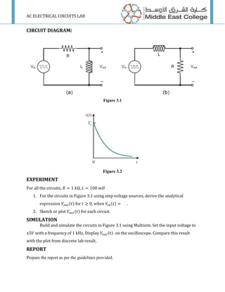

This document summarizes an experiment on the transient response of an RL circuit with a DC input. The experiment aims to study the step response of first-order circuits and understand the concept of the time constant. For an RL circuit with a step voltage input, the output can be expressed by an equation involving the initial and final circuit responses, and the time constant, which is the time required for the response to reach 63% of its final value. The time constant is equal to the inductance divided by the resistance. The circuit diagram and procedures for the experiment are provided.