Download as PDF, PPTX


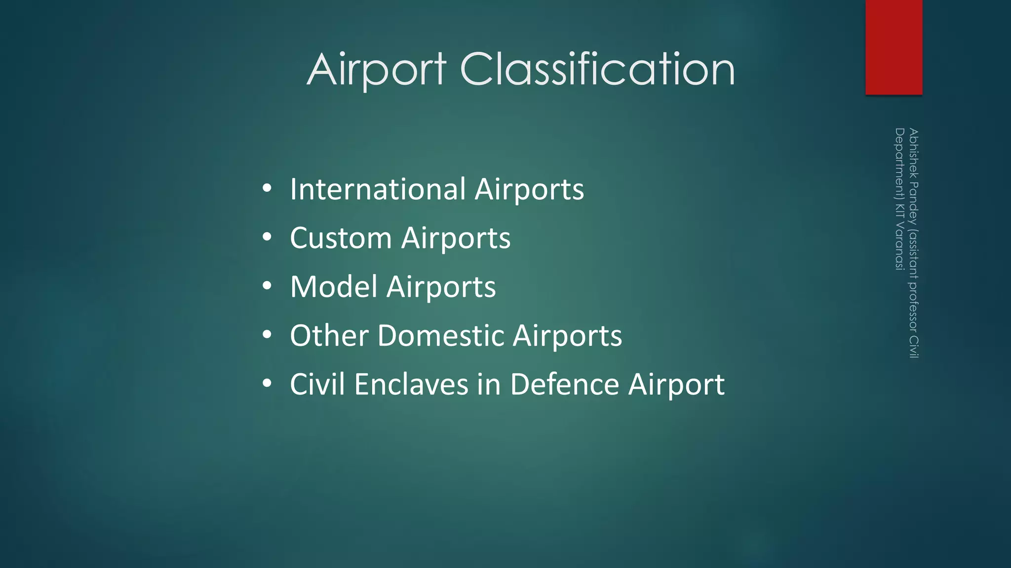
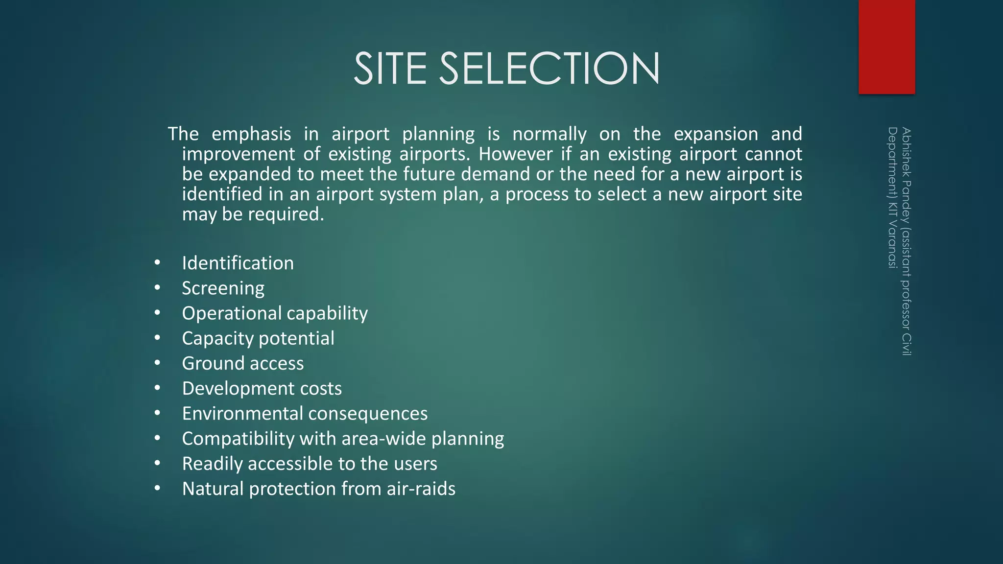


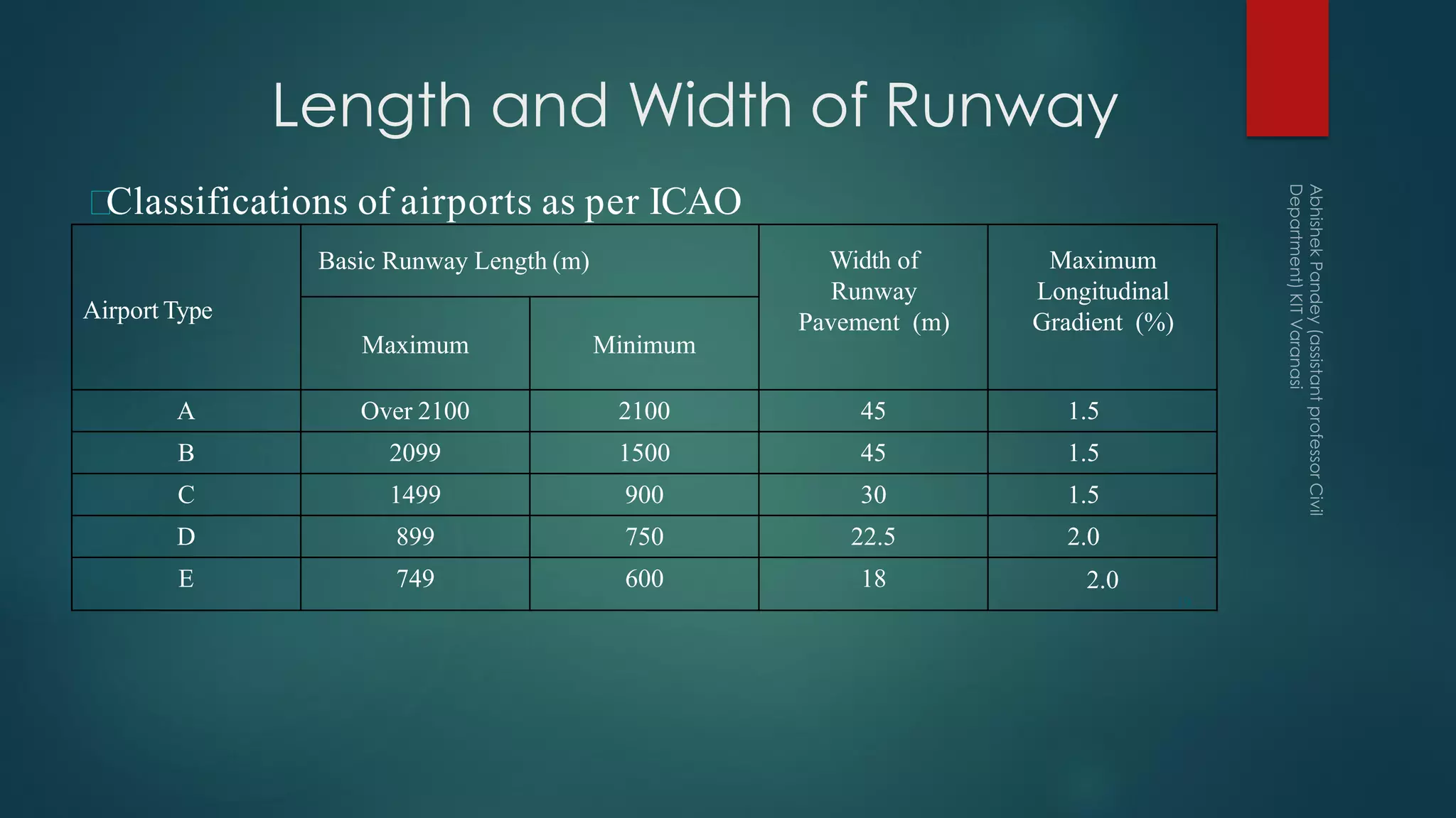


The document outlines key definitions and concepts related to airport engineering, including classifications of airports, components of airport layout, and factors influencing runway design. It emphasizes the importance of an airport master plan for future development and discusses various operational capabilities, geometric designs, and environmental considerations for airport sites. Additionally, it details runway configurations, length requirements based on aircraft performance, and corrections needed for elevation and temperature impacts on runway length.


