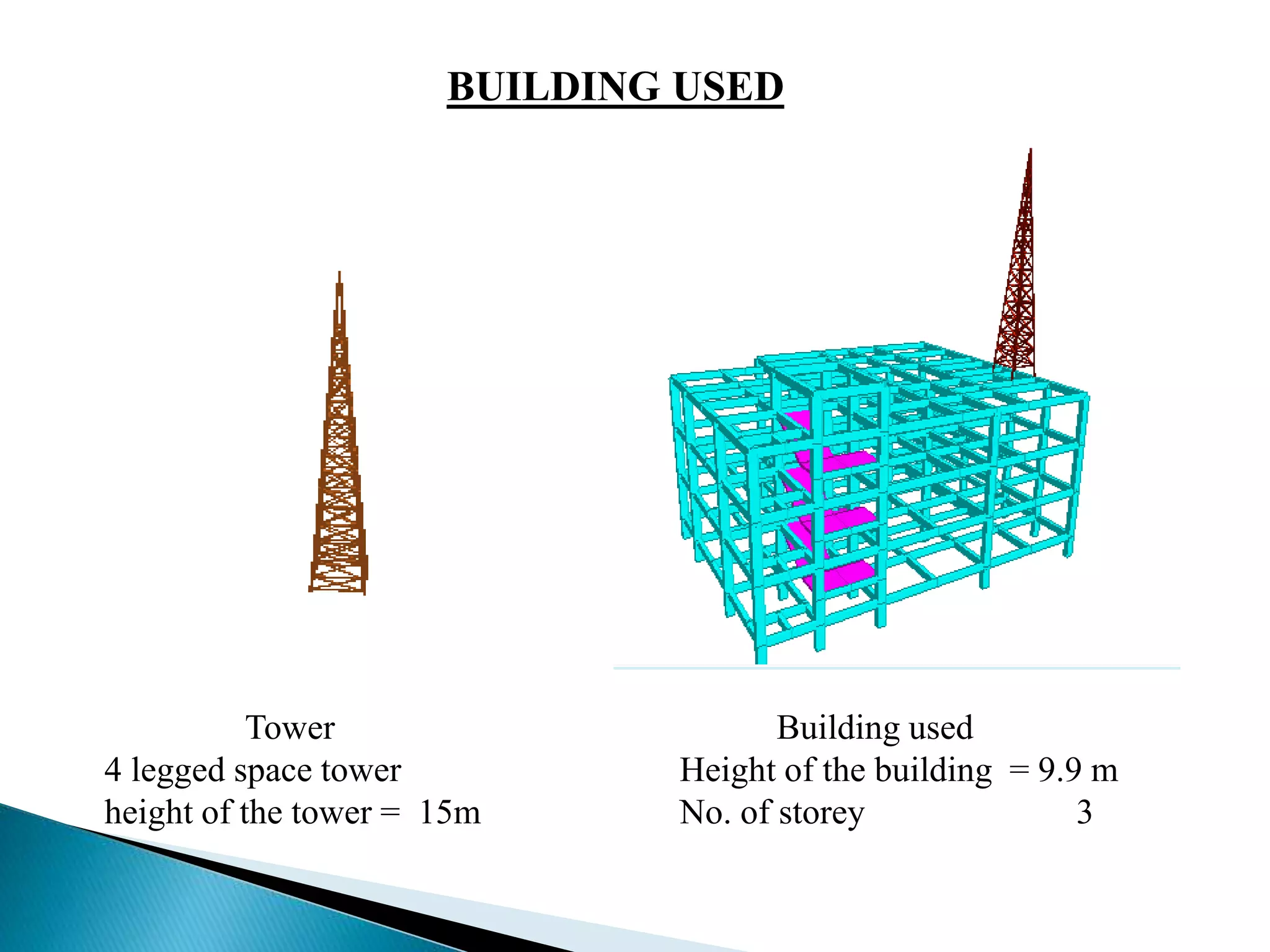
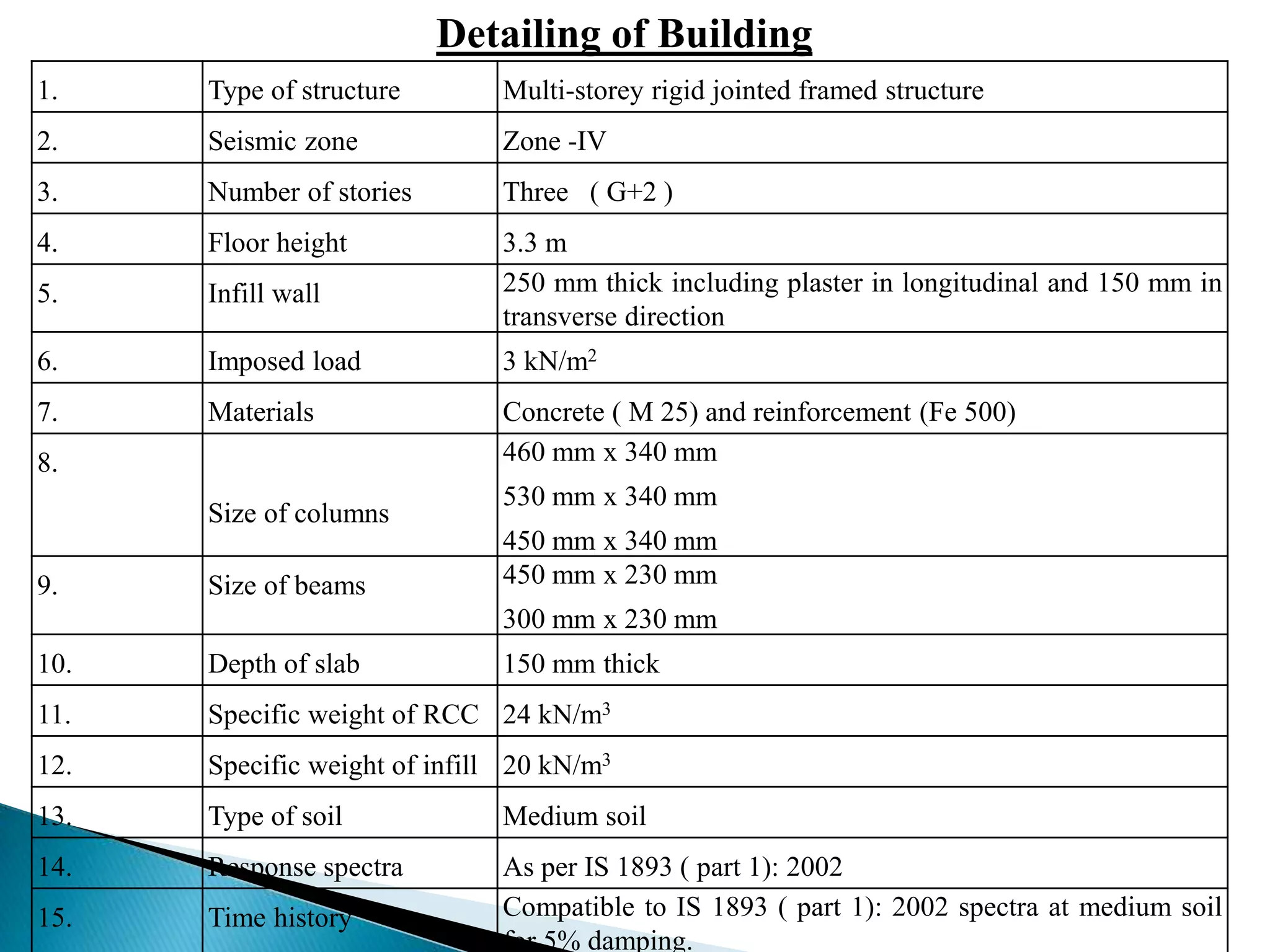
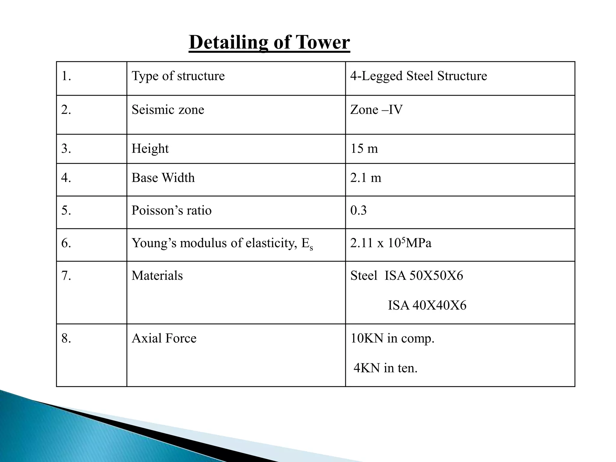
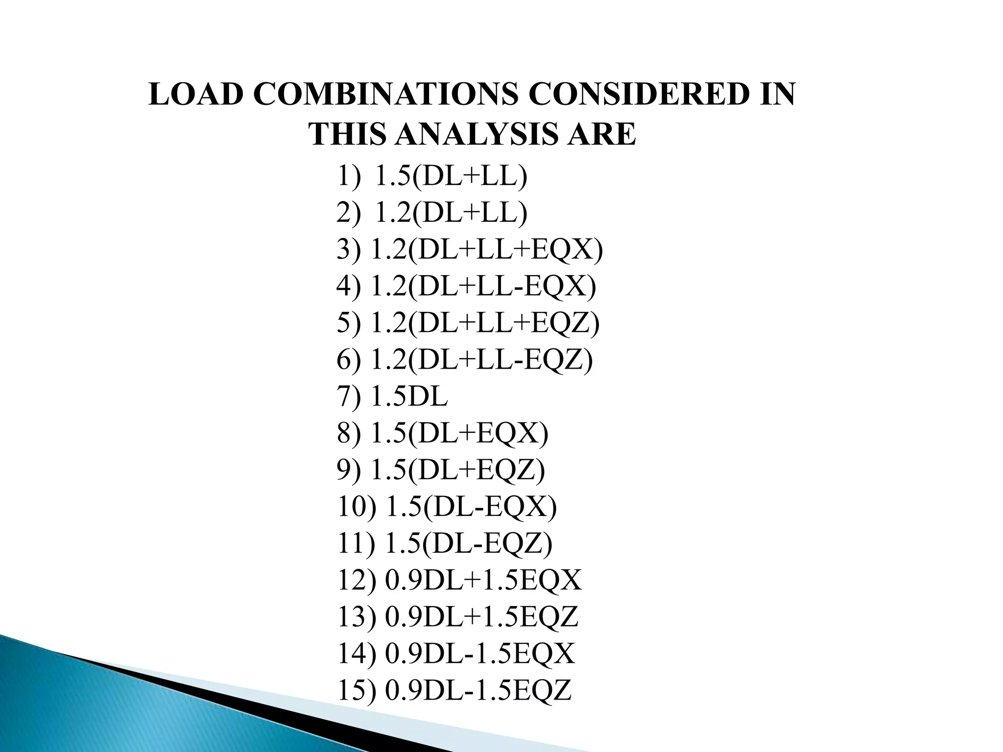
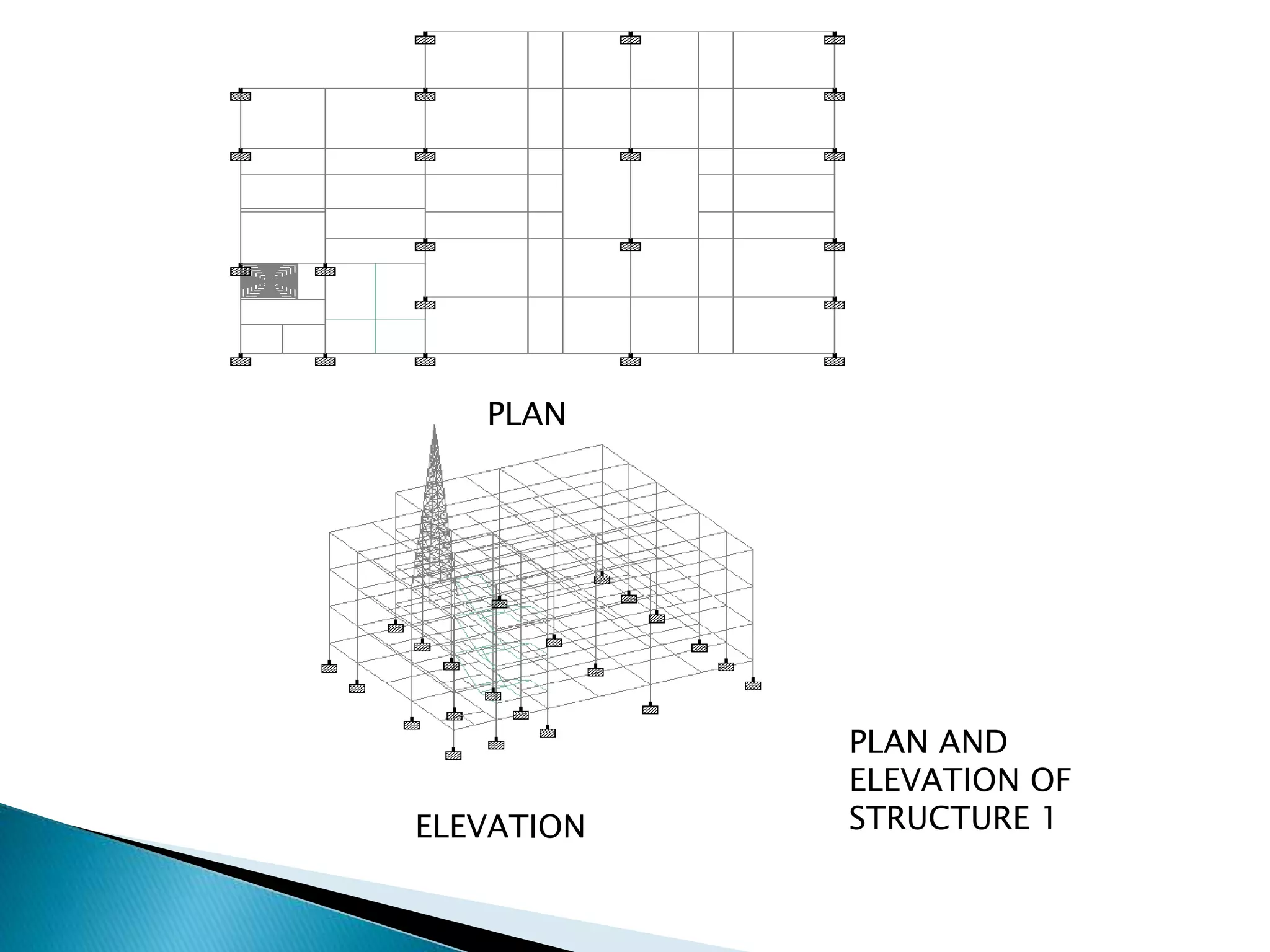
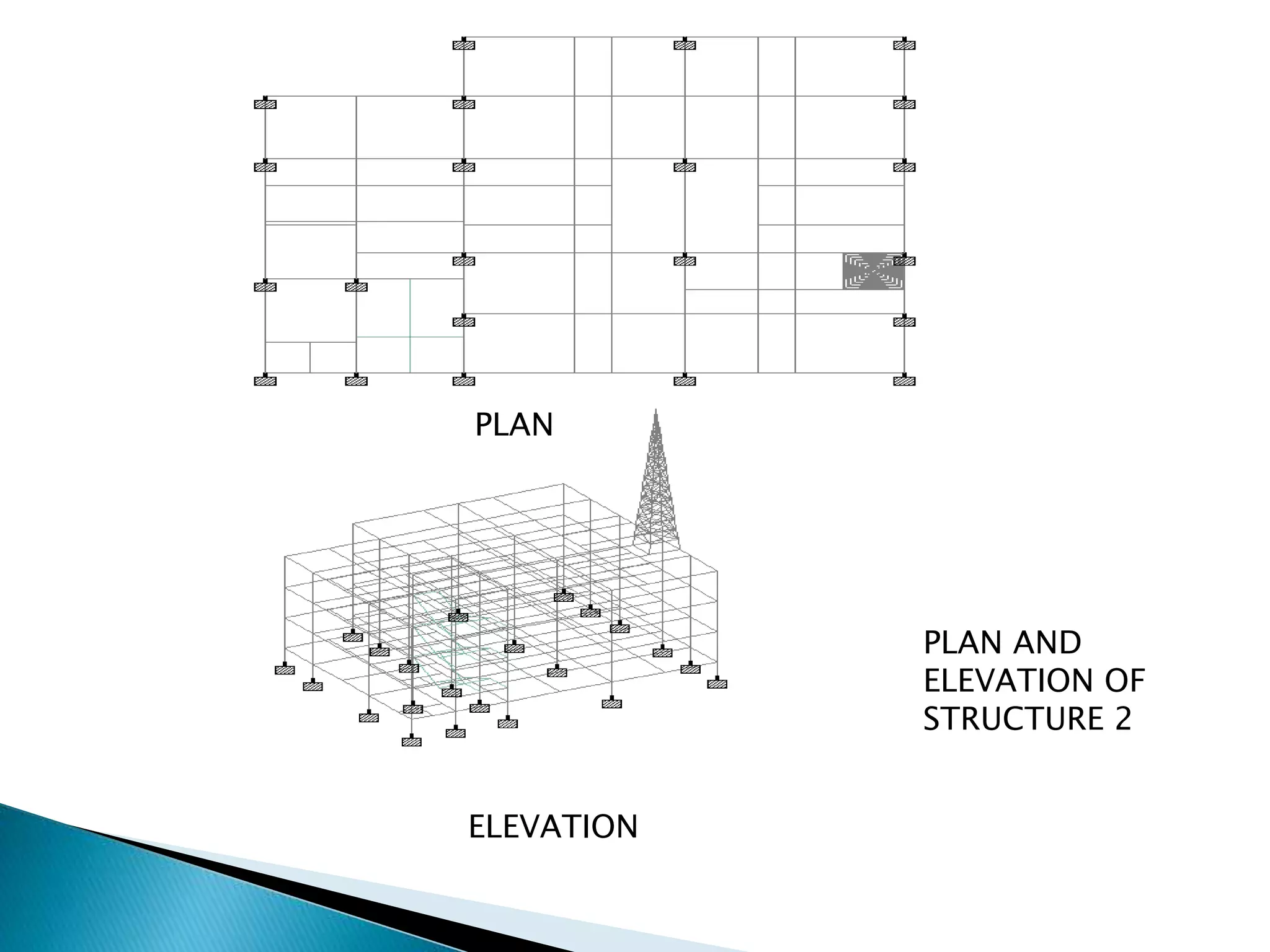
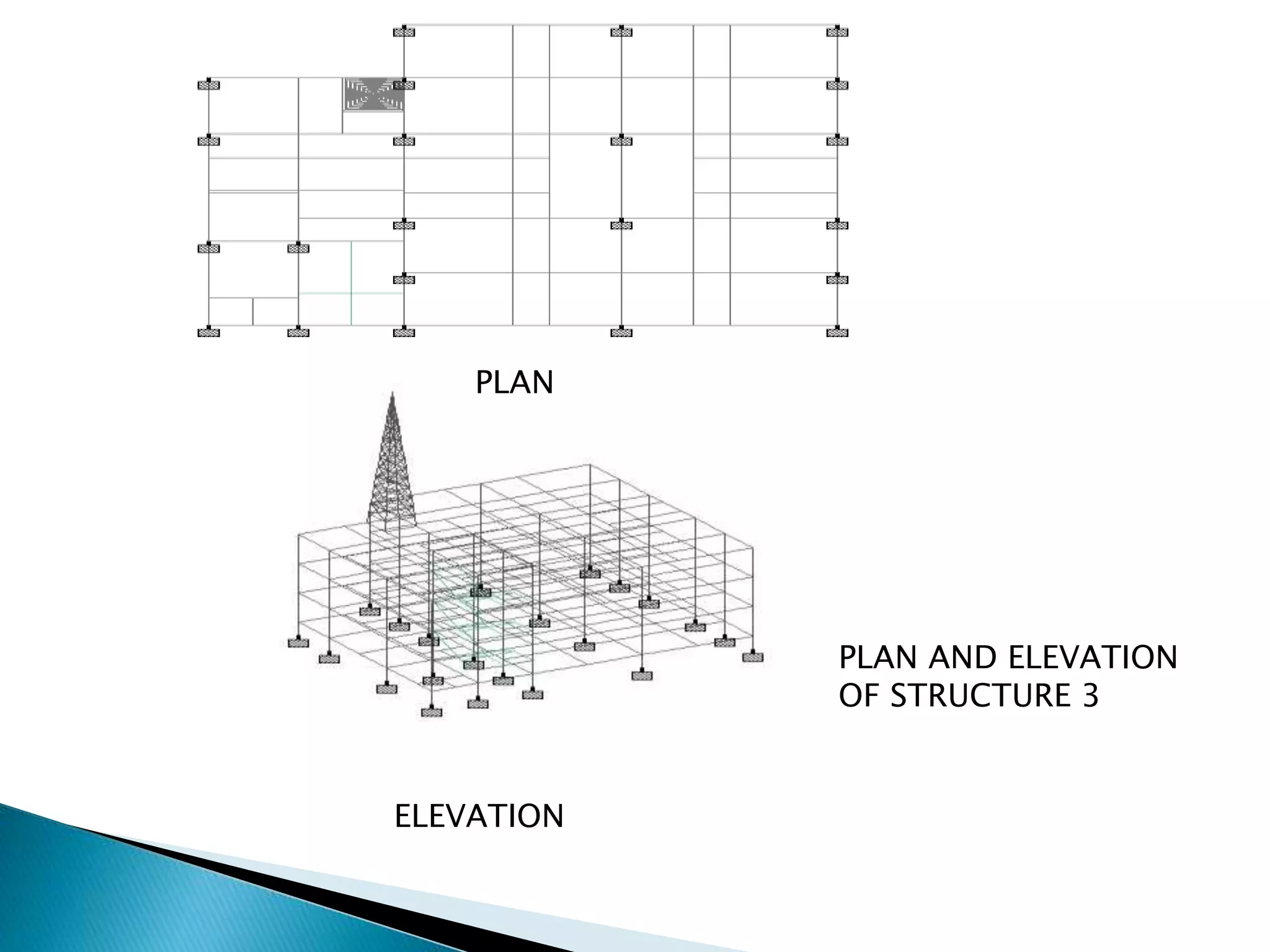
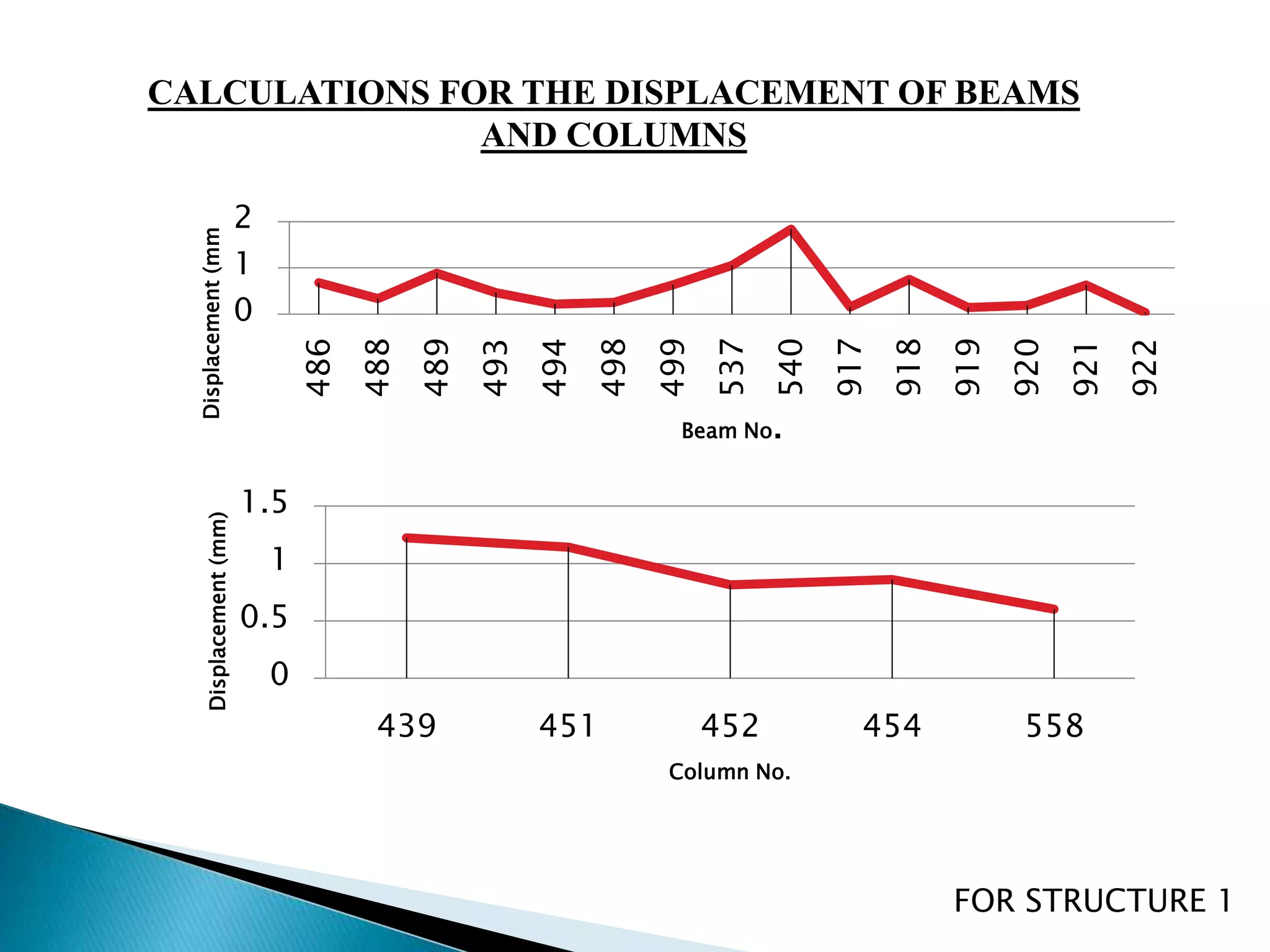
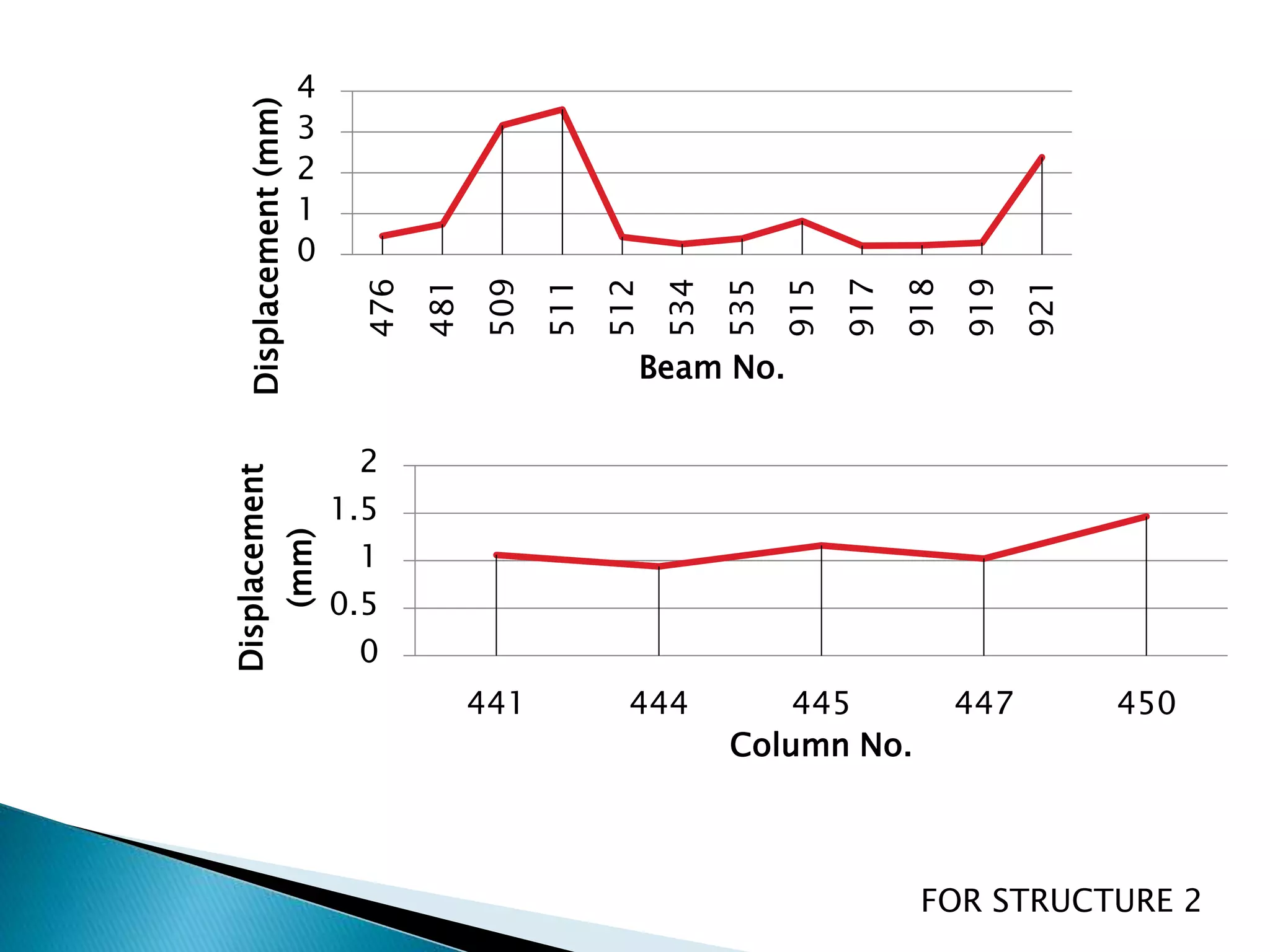
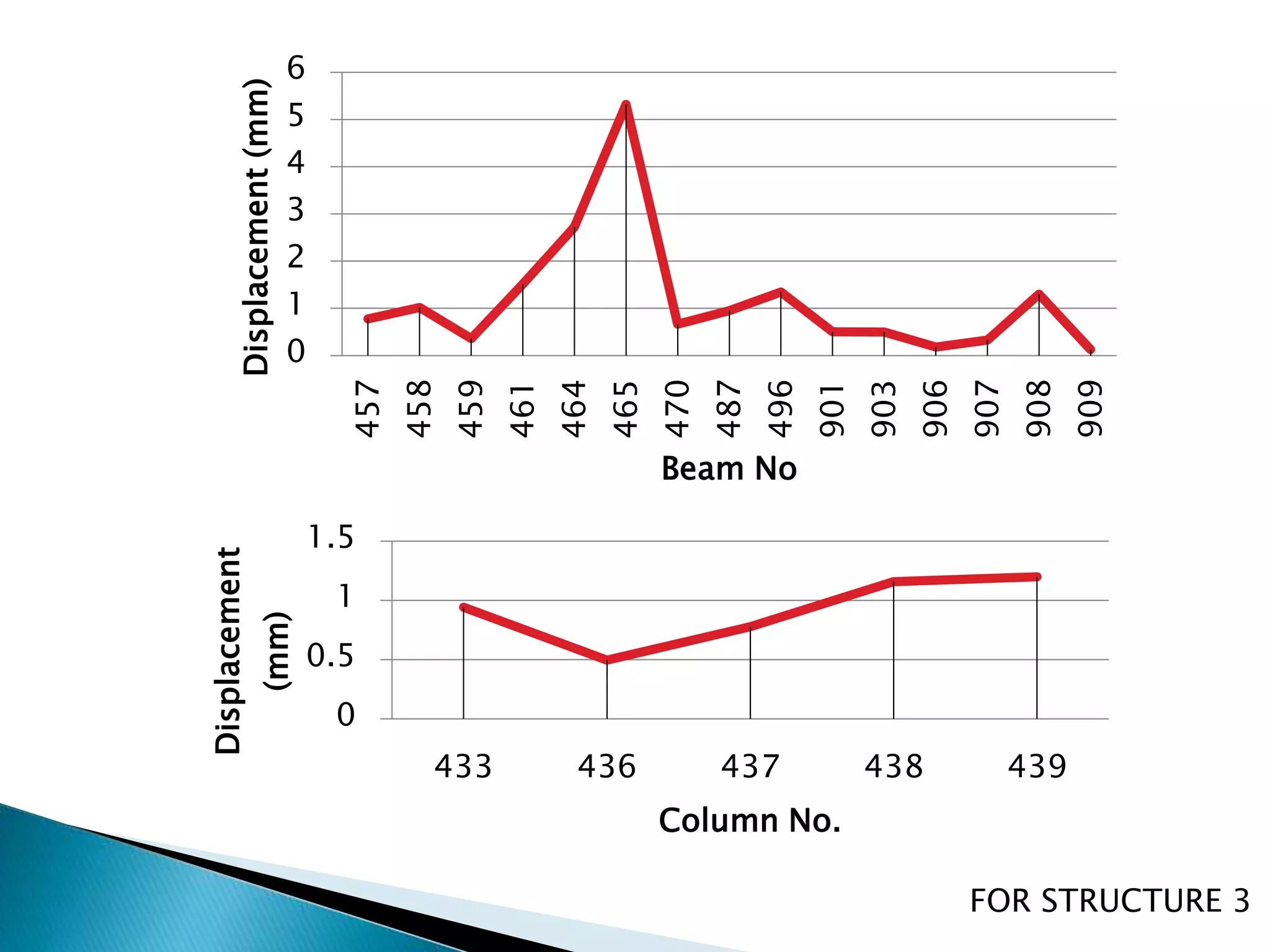
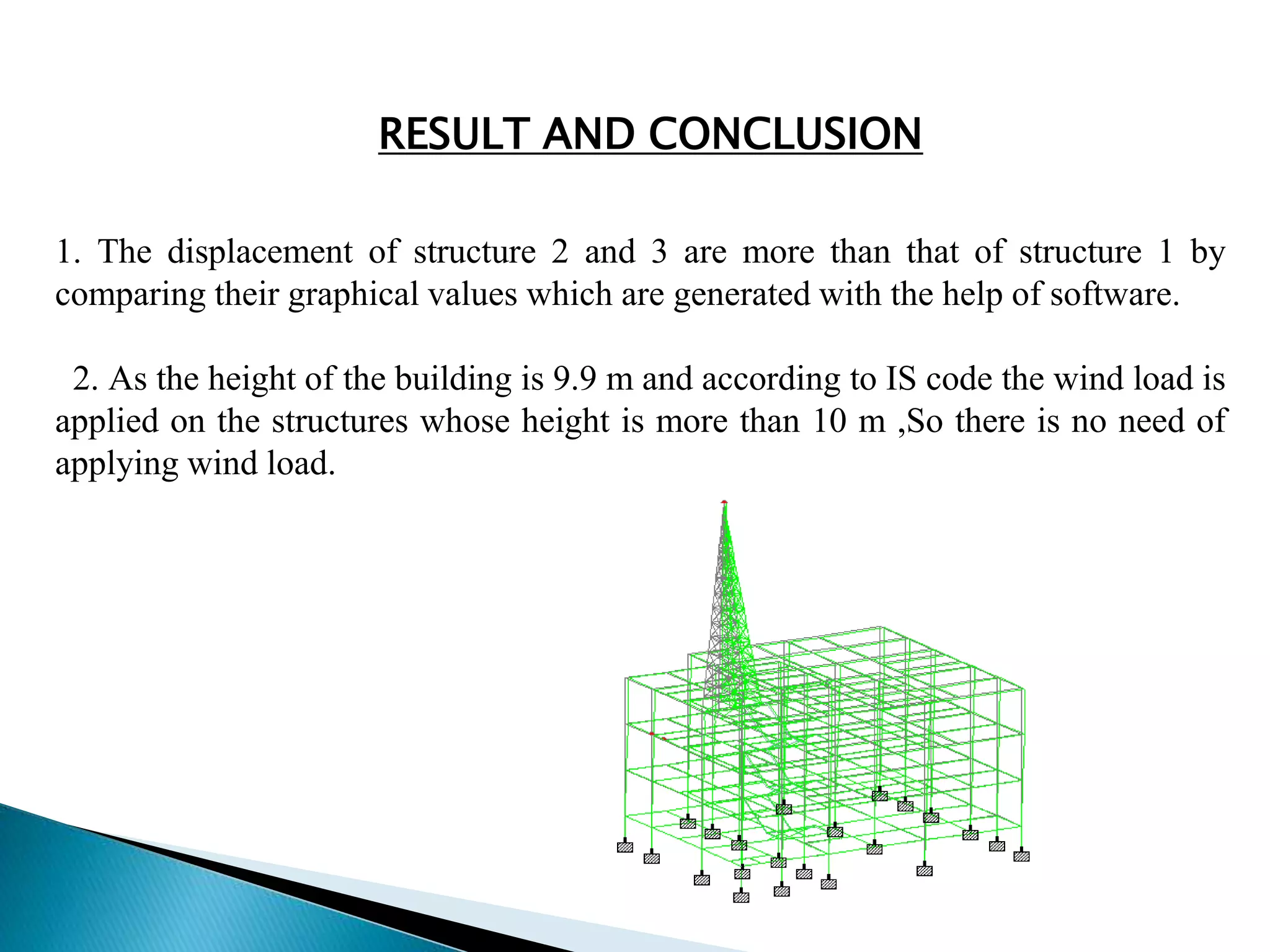
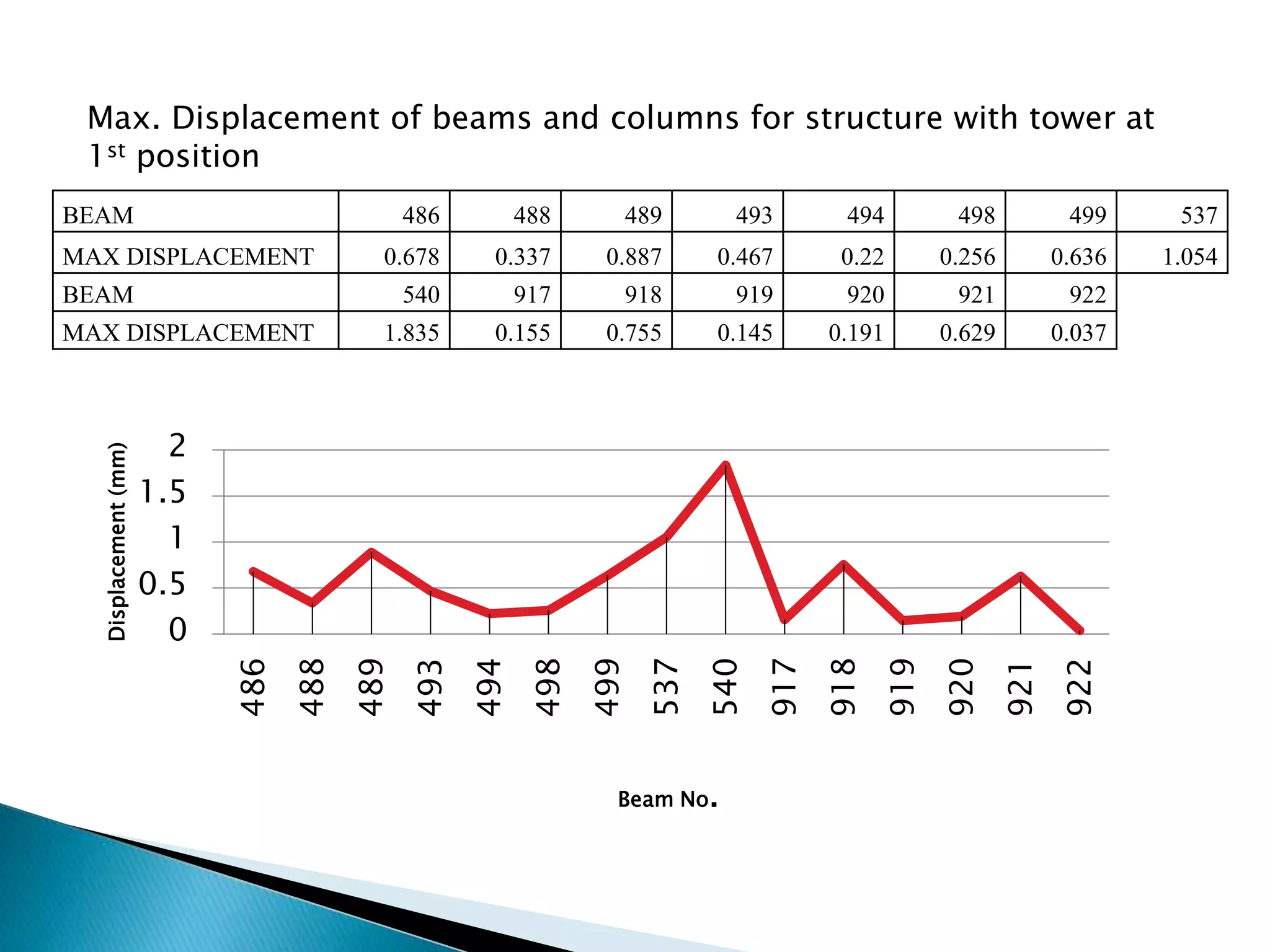
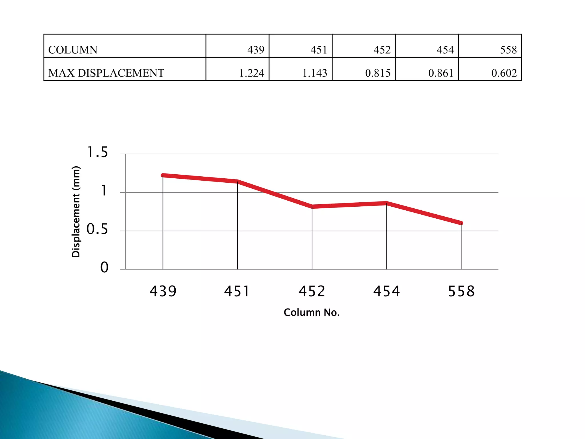
This document summarizes the dynamic analysis of a multi-storey framed structure with a roof tower conducted using STAAD-Pro. The objectives were to model the tower and building, study their response using the response spectra method under seismic loading, and analyze wind loads. A 3-storey building with dimensions and material properties was modeled along with a 15m 4-legged steel tower. Load combinations, mode shapes, and response spectra were defined to obtain displacements of beams and columns for the three structures under different load cases. Structure 2 and 3 showed higher displacements than Structure 1. Wind loads were not considered as the building height was under 10m.
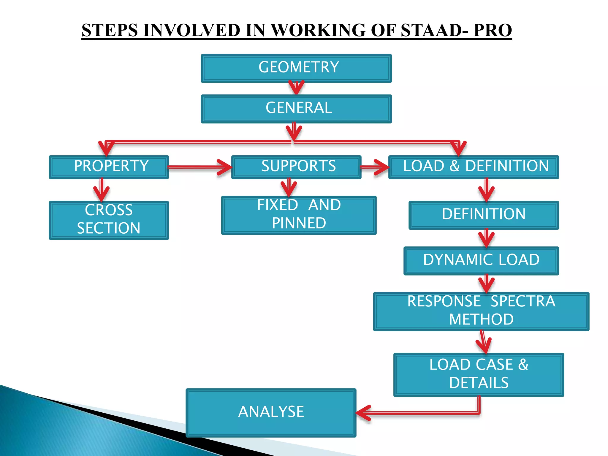
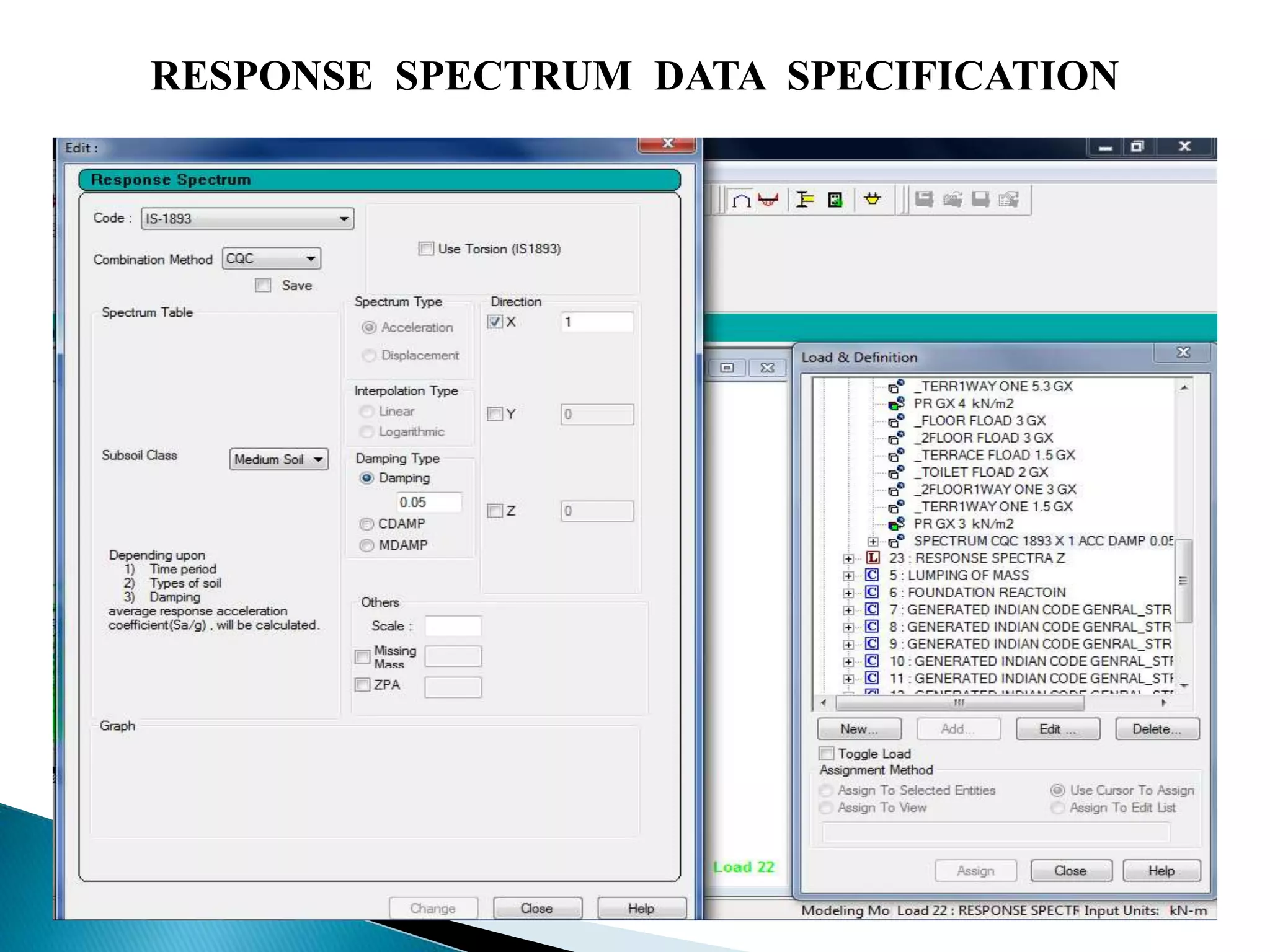
![RESPONSE SPECTRUM METHOD BY USING
STAADPRO
The design lateral shear force at each floor in each mode is
computed by STAAD in accordance with the IS: 1893 (Part 1) -
2002
STAAD utilizes the following procedure to generate the lateral seismic
loads.
[1] User provides the value for as factors for input spectrum. I* Z / 2 R
[2] Program calculates time periods for first six modes or as specified
by the user.
[3] Program calculates Sa/g for each mode utilizing time period and
damping for each mode.](https://image.slidesharecdn.com/multistoreyframedstructure-140908092359-phpapp01/75/Dynamic-Analysis-of-Multistorey-framed-structure-with-roof-tower-9-2048.jpg)
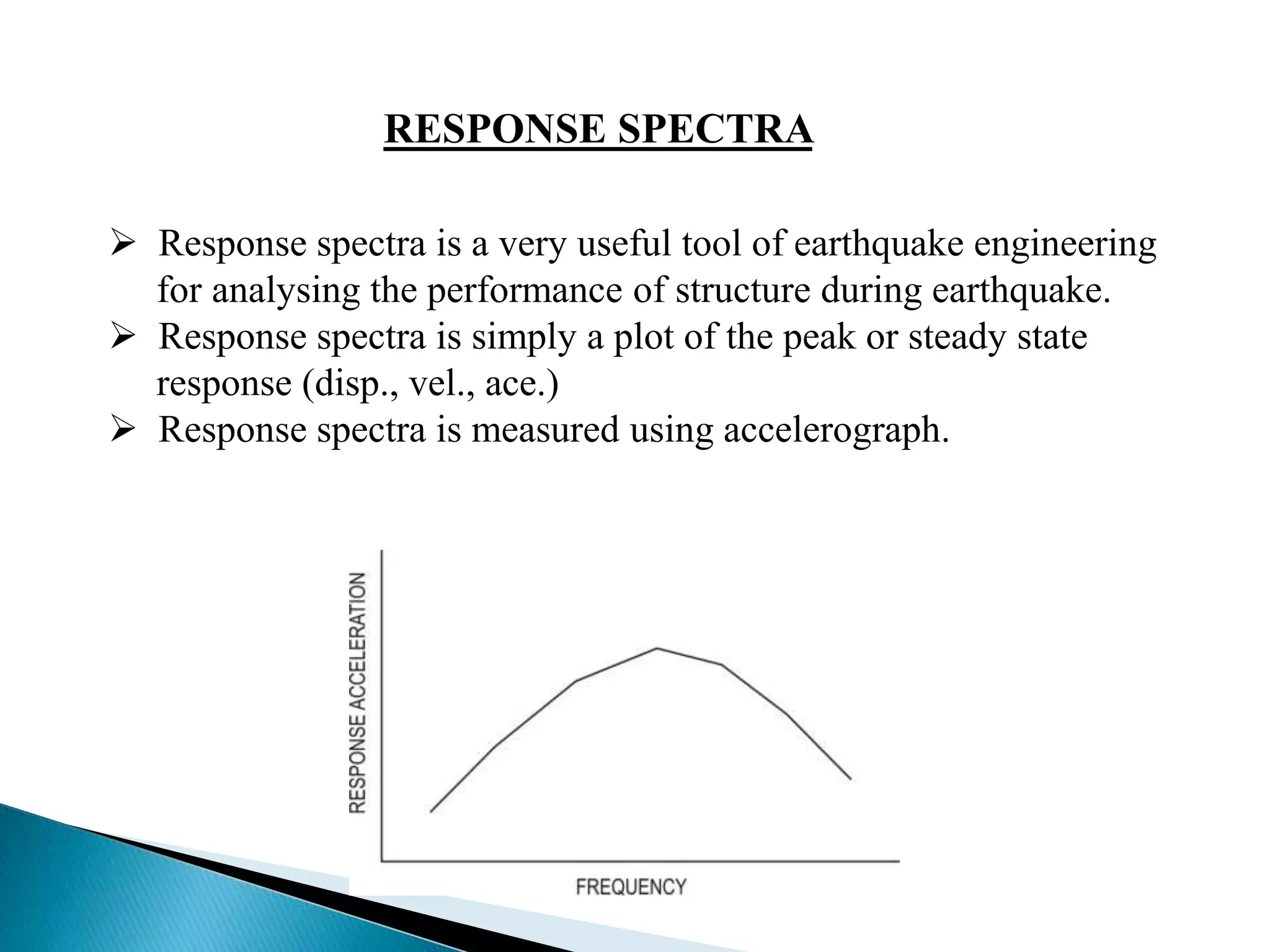
![[4] The program calculates design horizontal acceleration spectrum
for different modes
[5] The program then calculates mode participation factor for different
modes.
[6] The peak lateral seismic force at each floor in each mode is
calculated.
[7] All response quantities for each mode are calculated.
[8] The peak response quantities are then combined as per method
(CQC or SRSS or ABS ) as defined by the user to get the final results](https://image.slidesharecdn.com/multistoreyframedstructure-140908092359-phpapp01/75/Dynamic-Analysis-of-Multistorey-framed-structure-with-roof-tower-10-2048.jpg)


![[Group 05] Multi-storey Timber Office](https://cdn.slidesharecdn.com/ss_thumbnails/group05-130521124559-phpapp01-thumbnail.jpg?width=640&height=640&fit=bounds)


