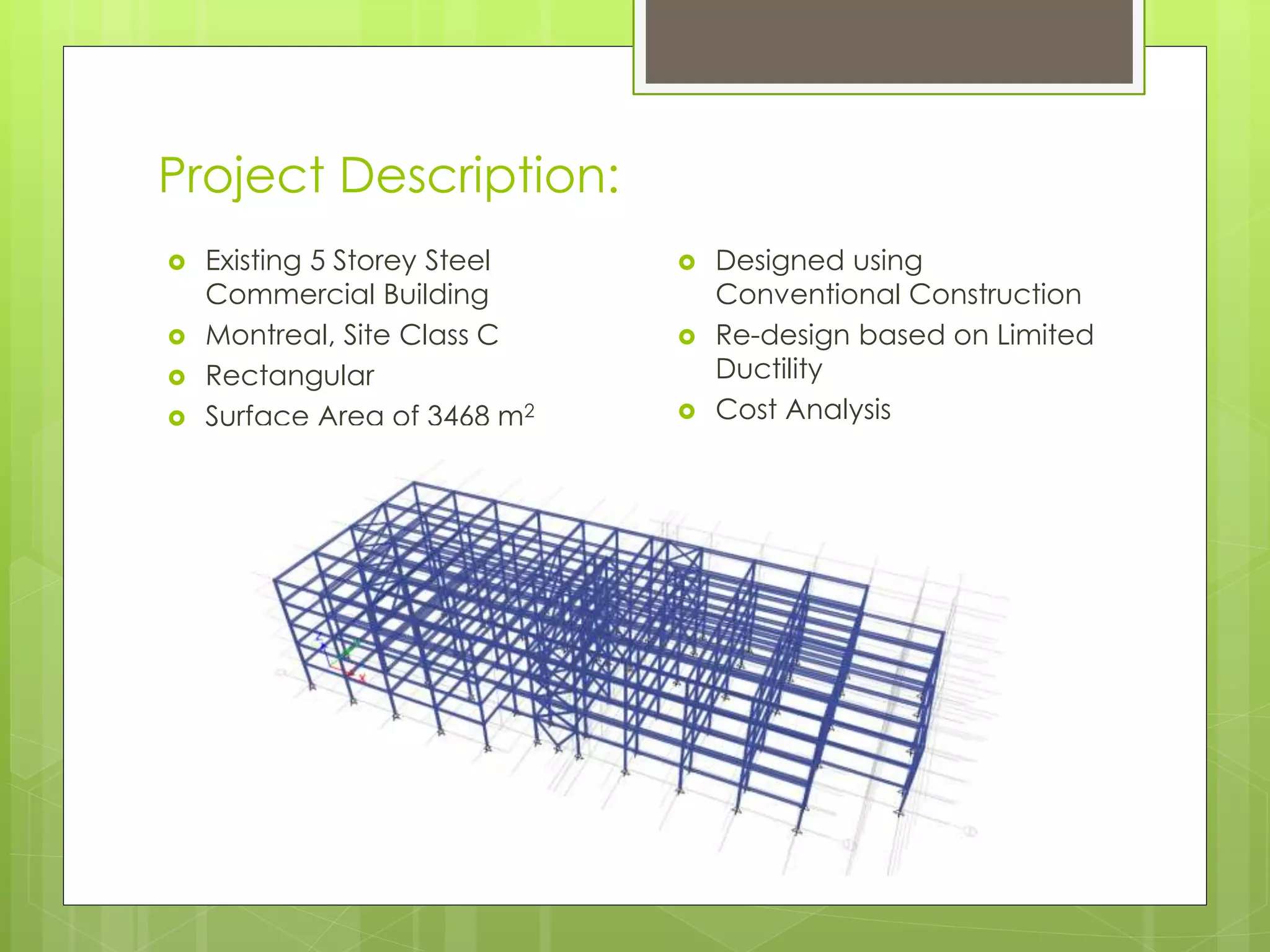
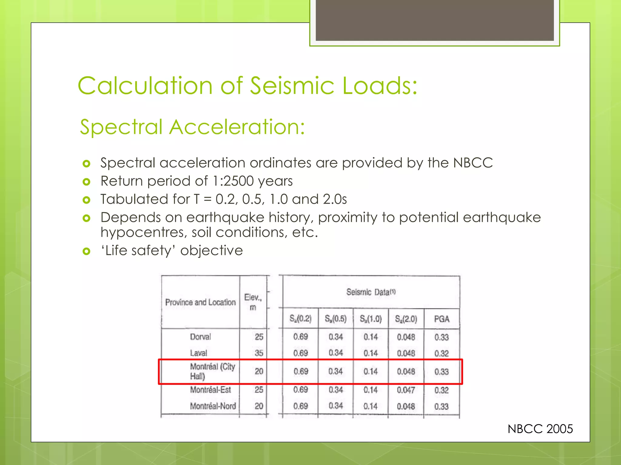
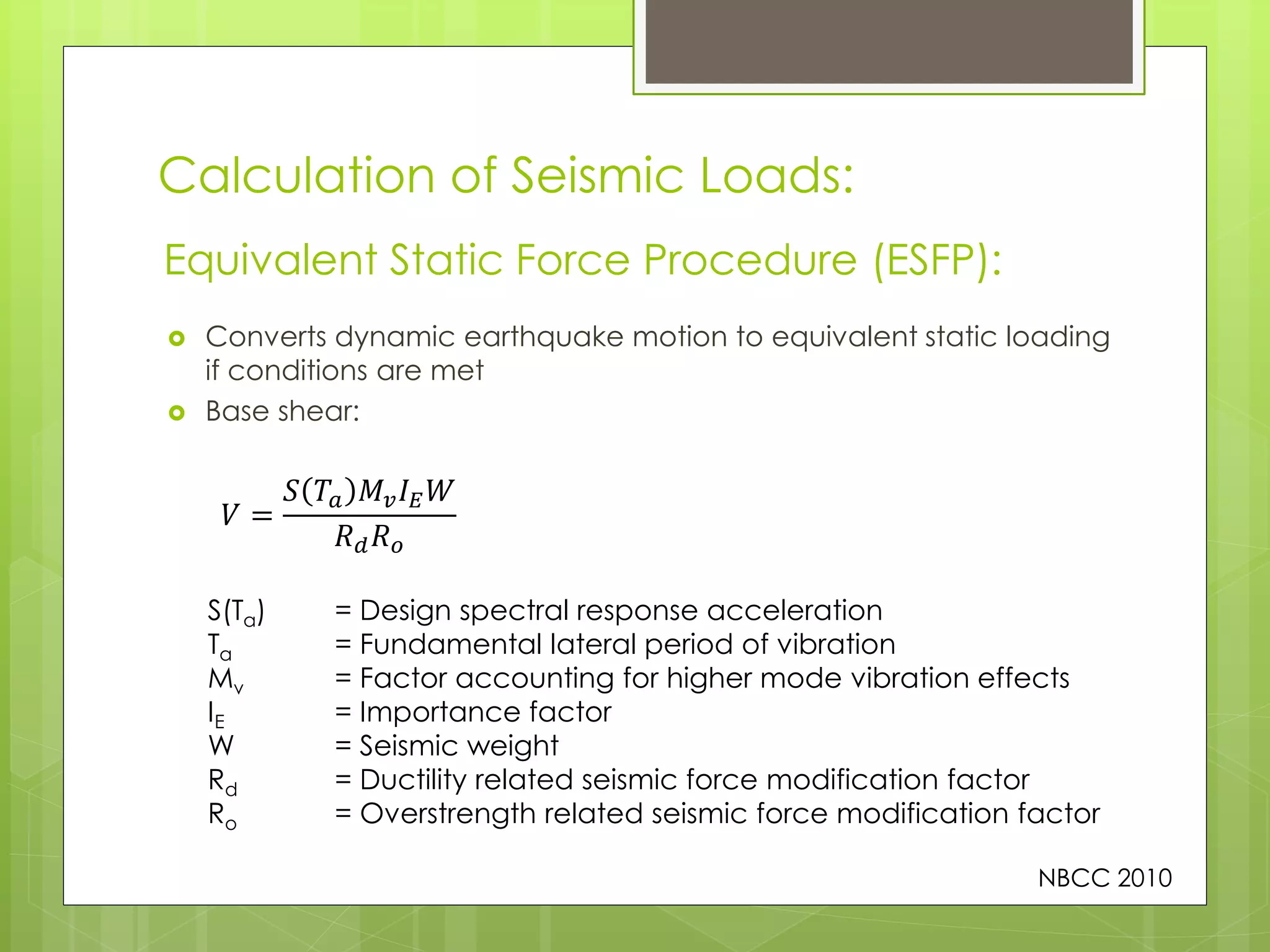
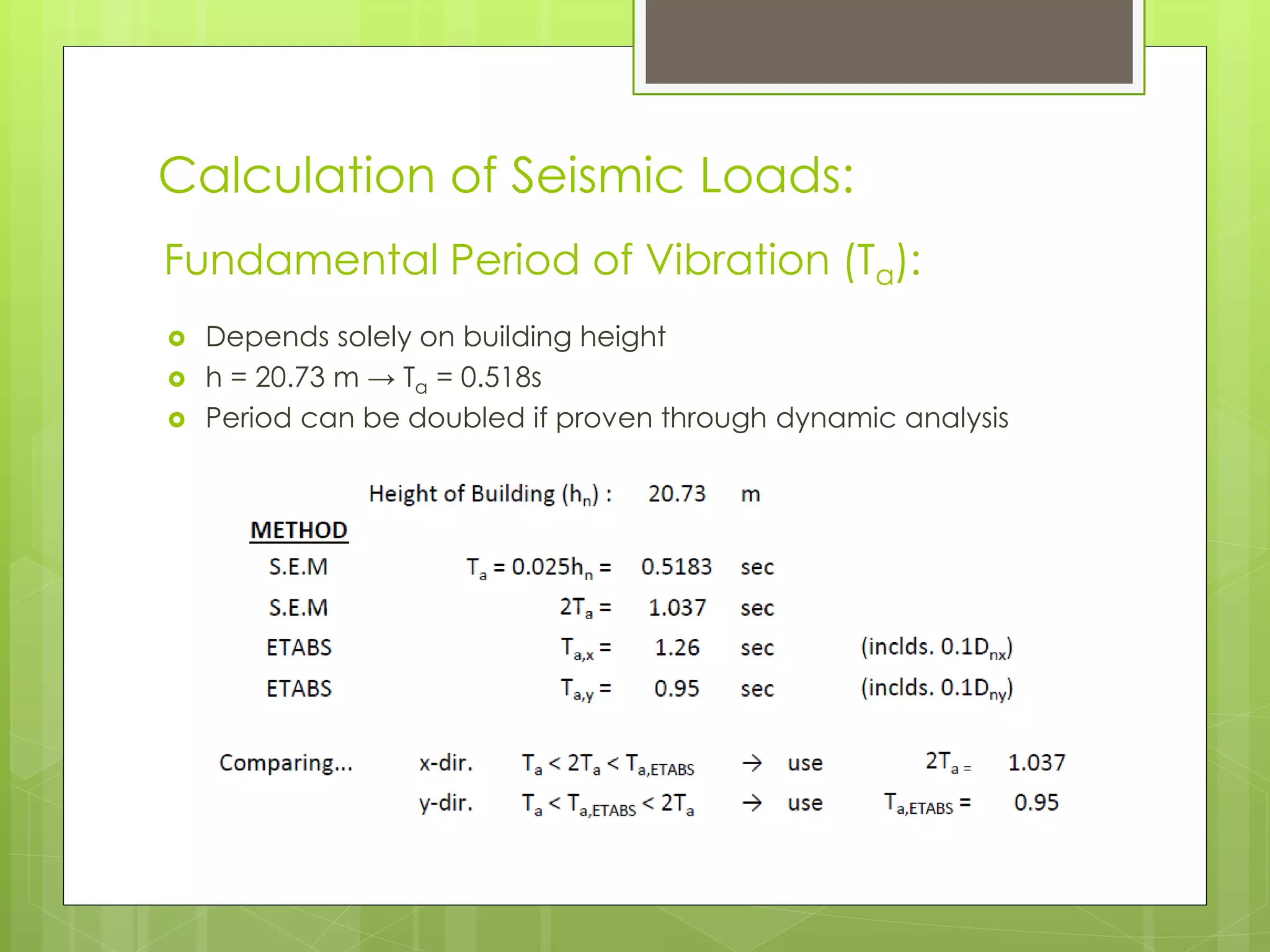
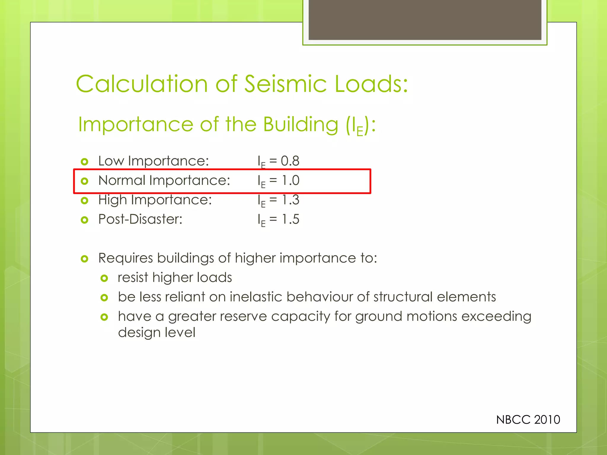
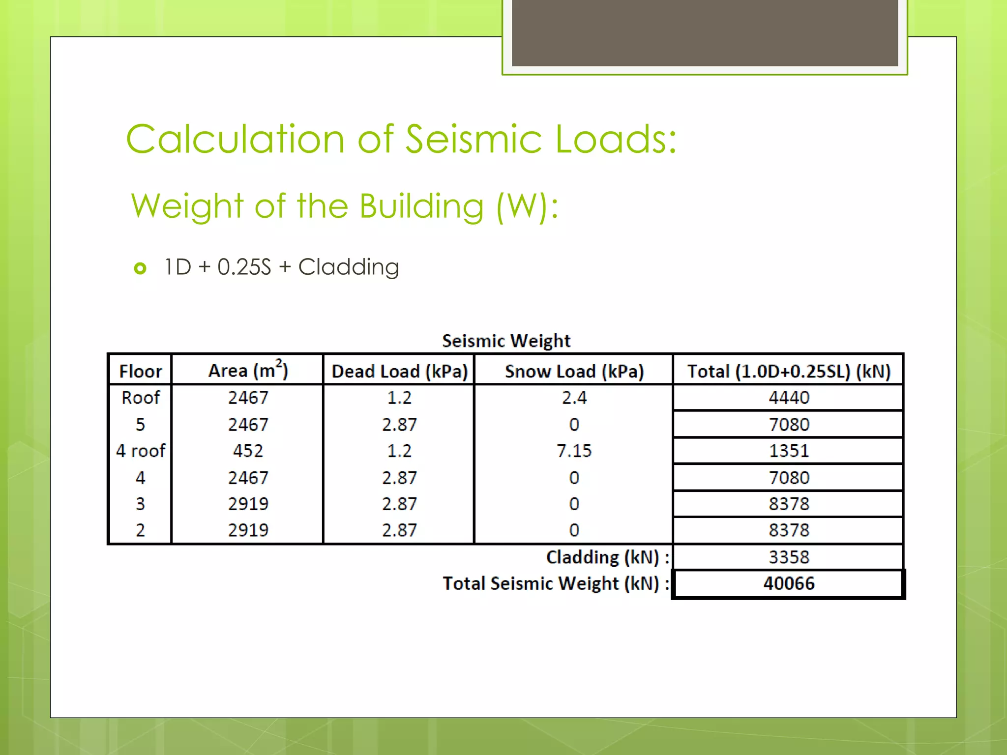
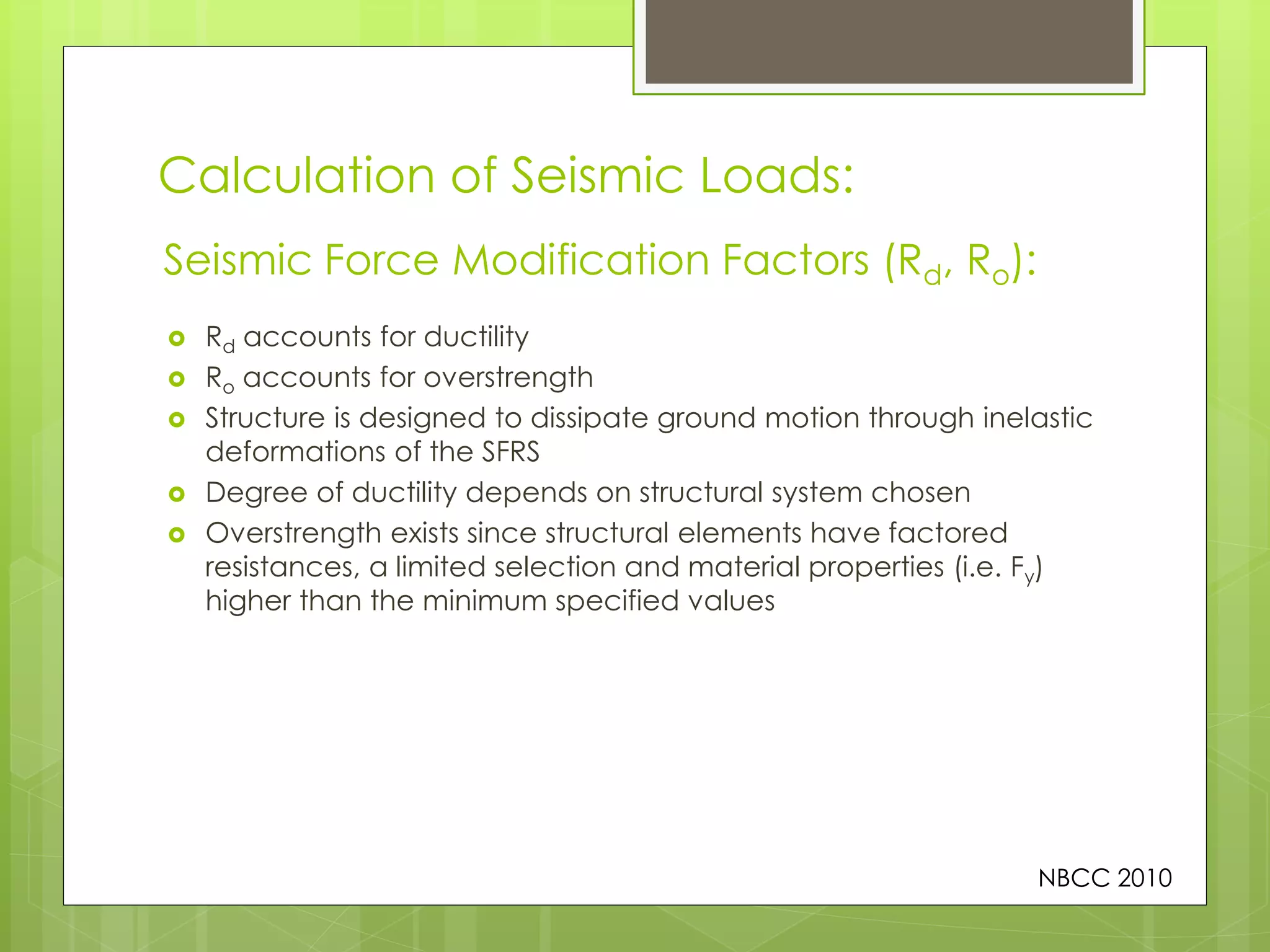
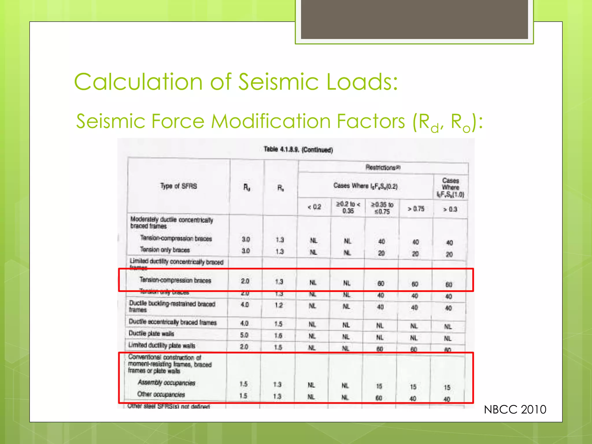
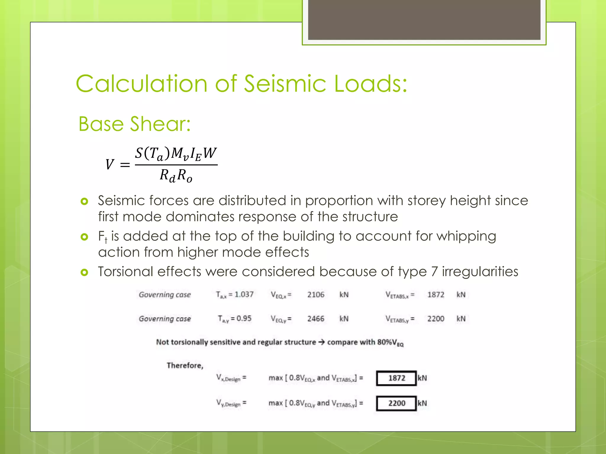
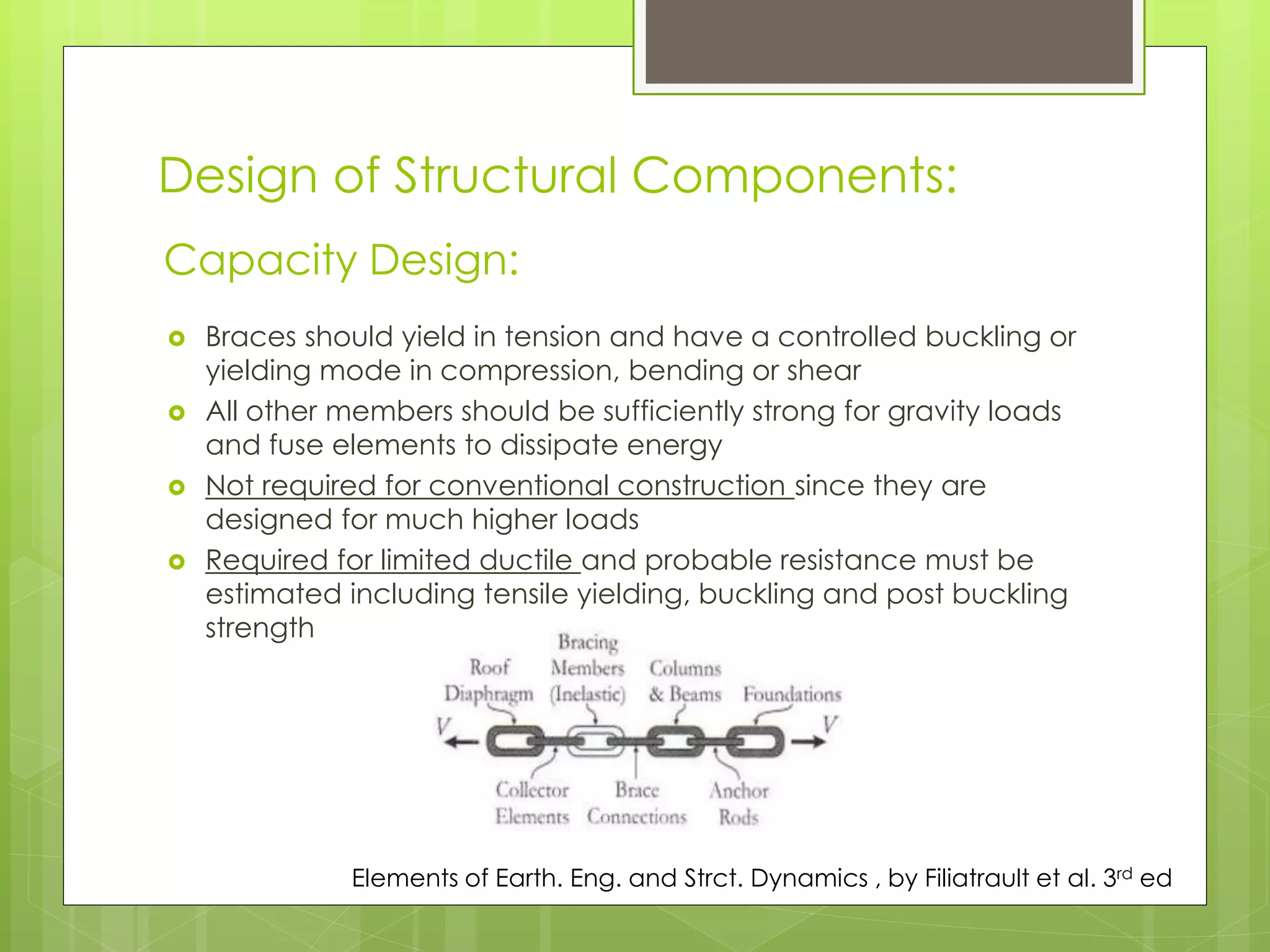
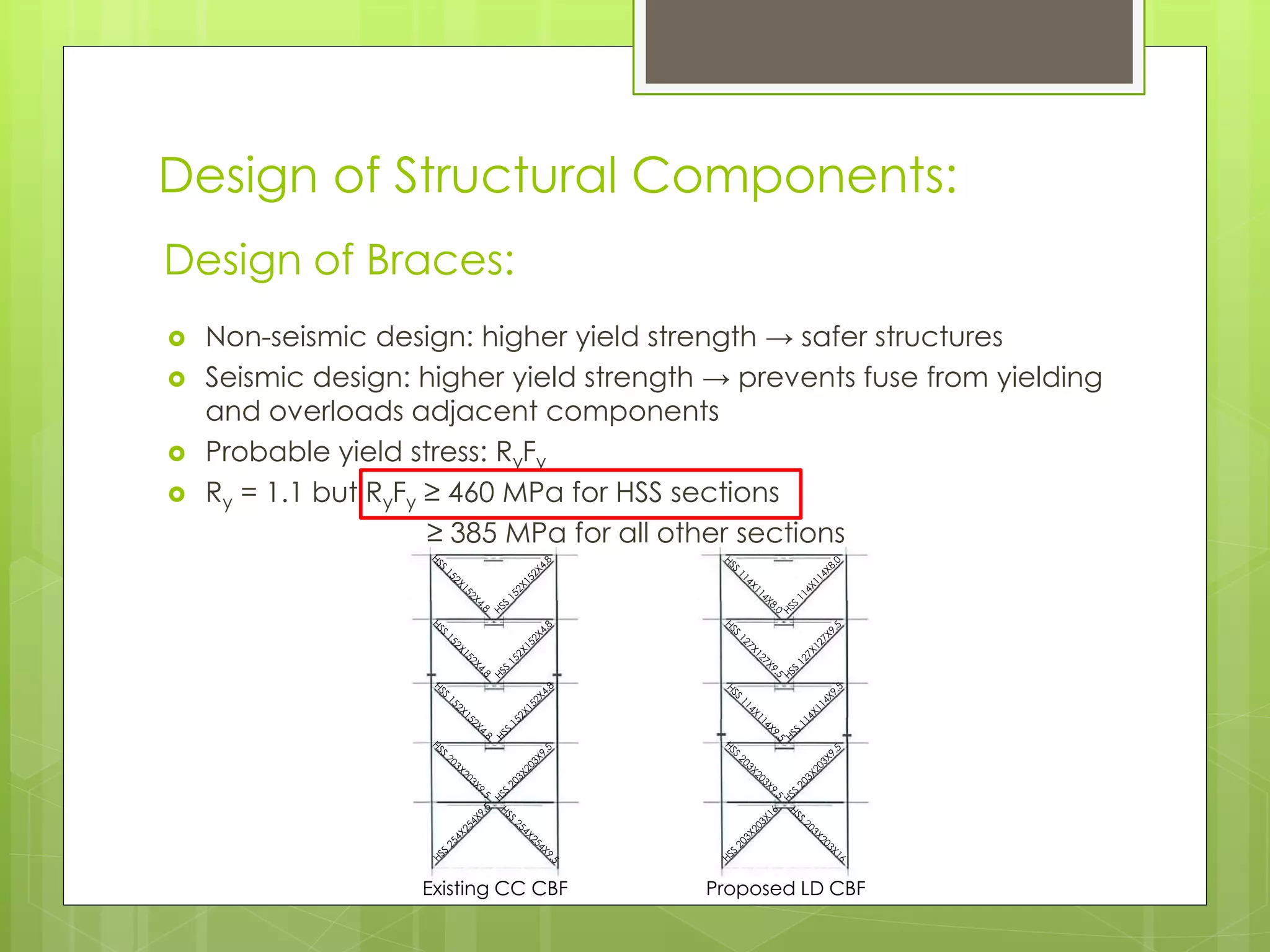
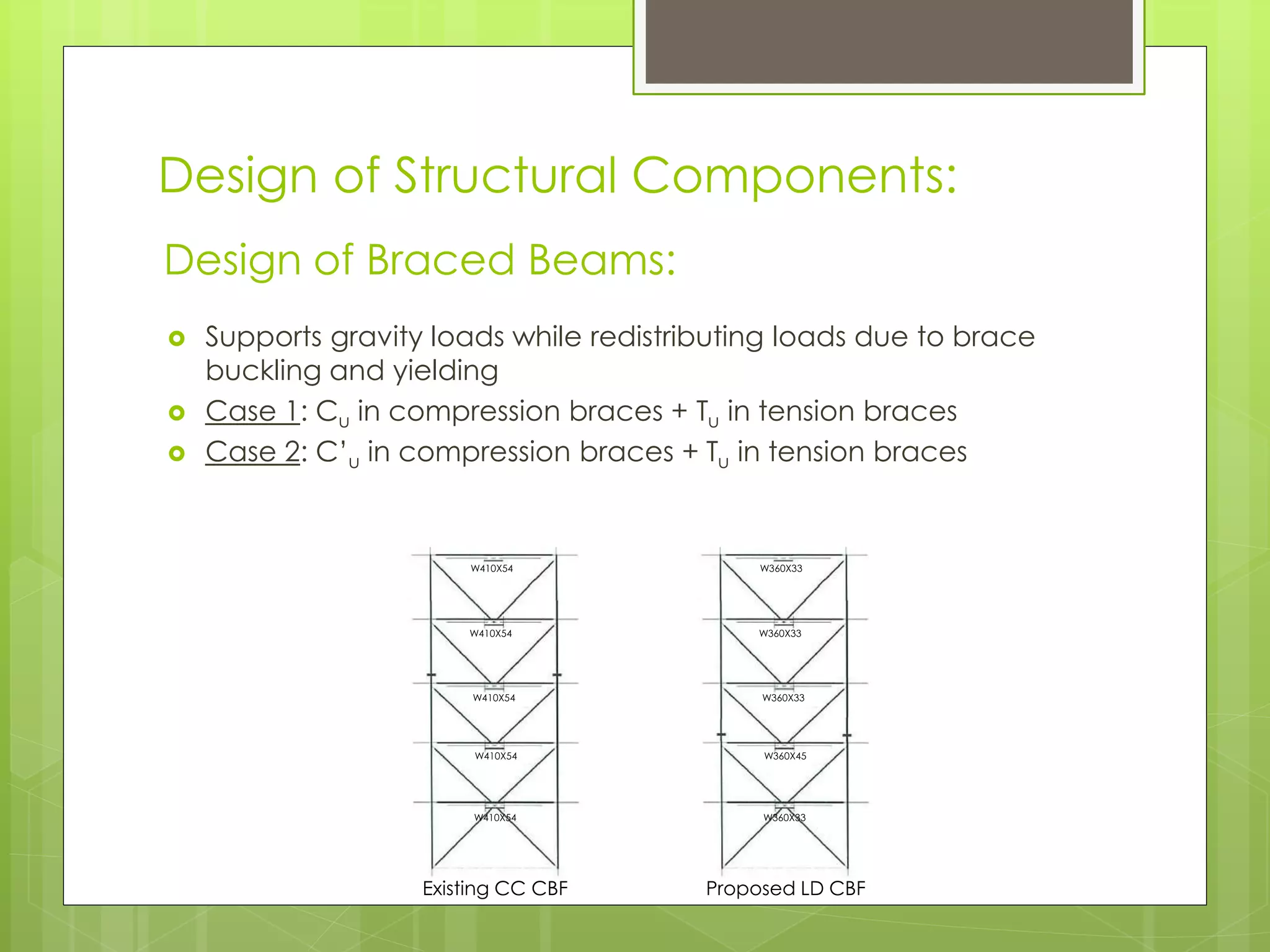
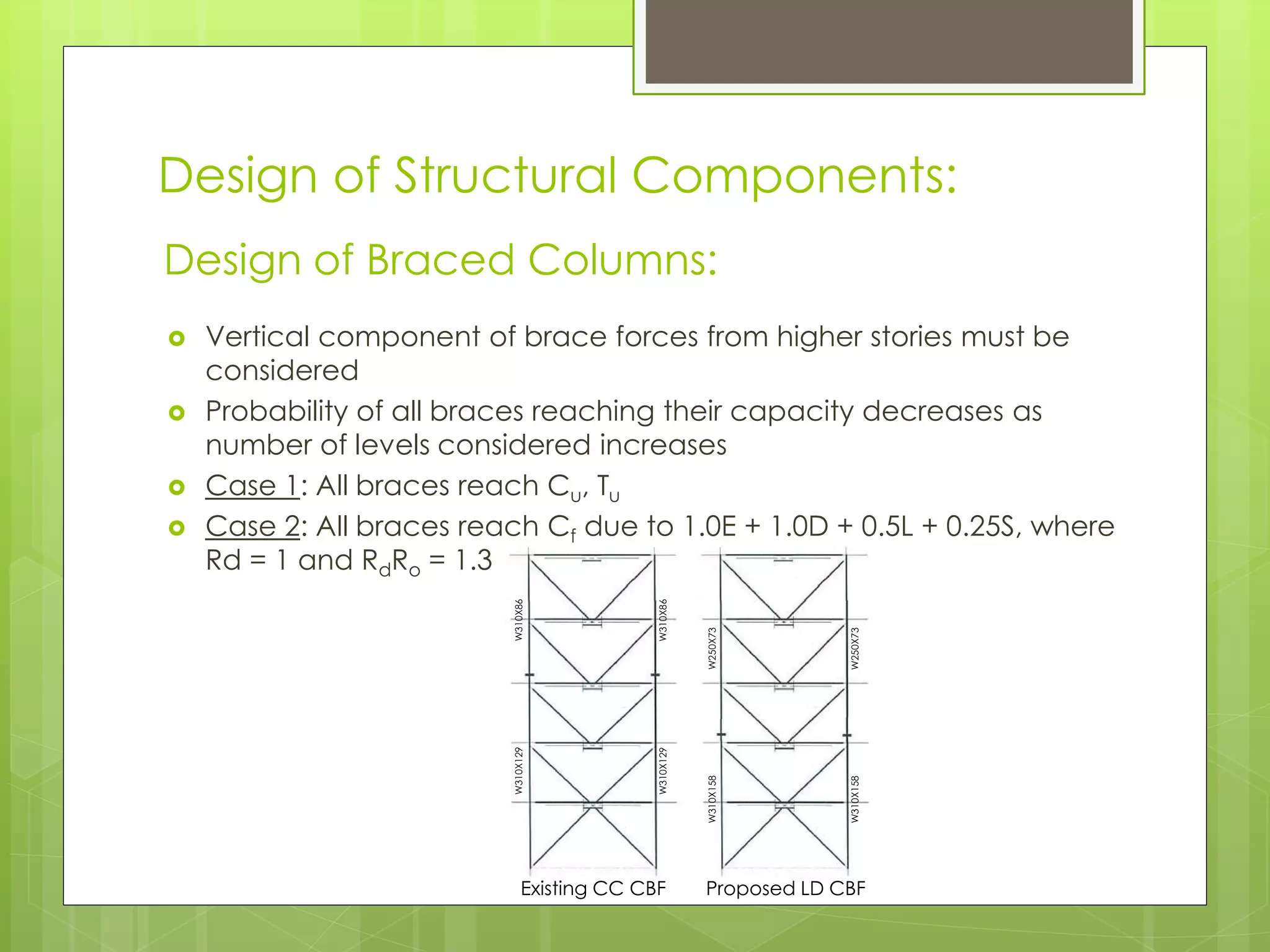
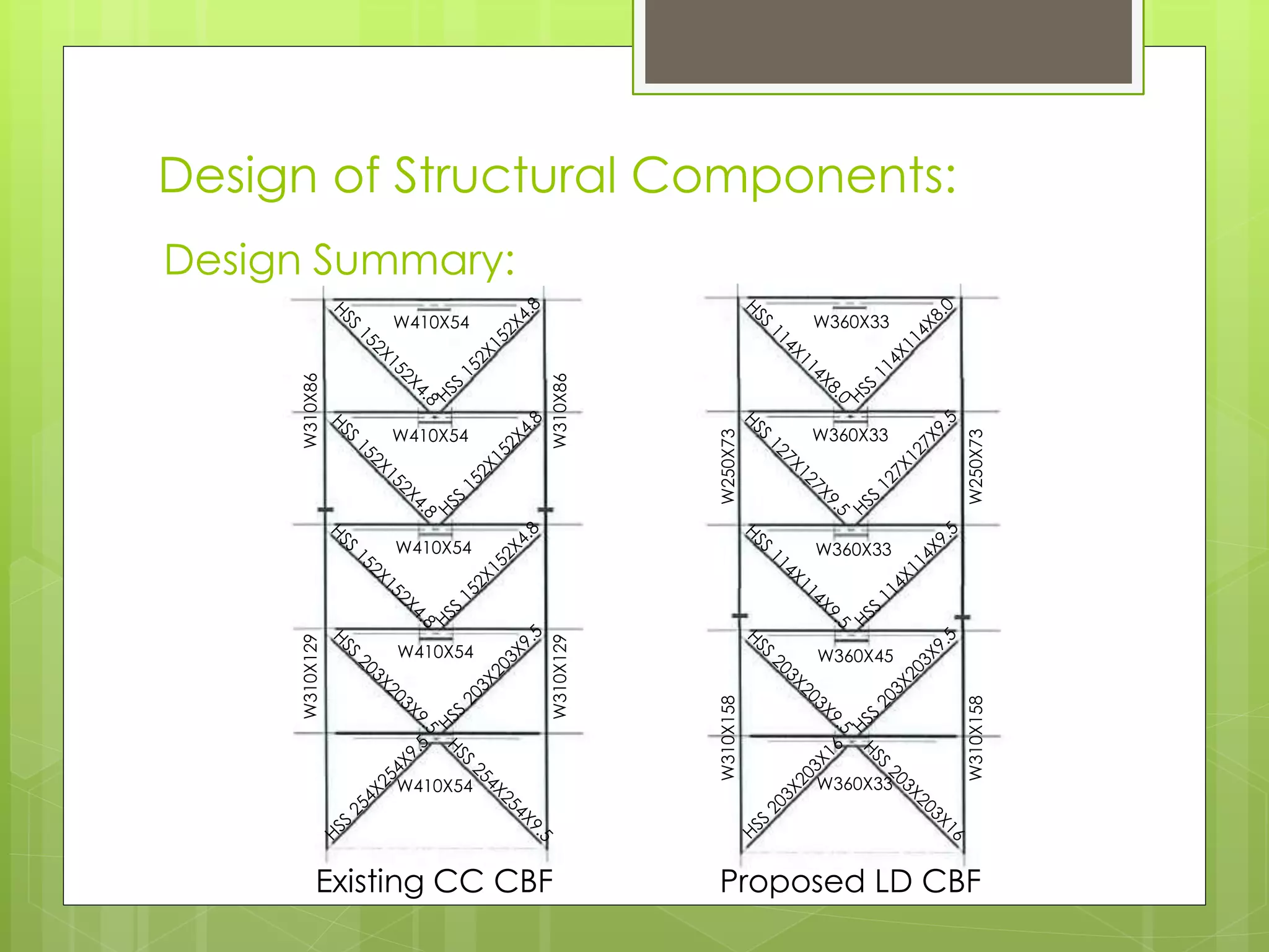
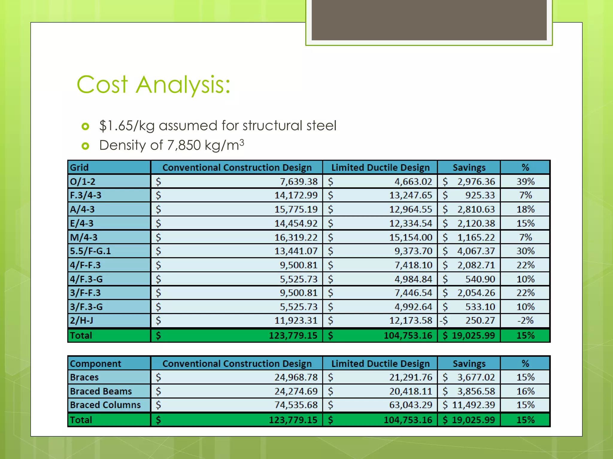
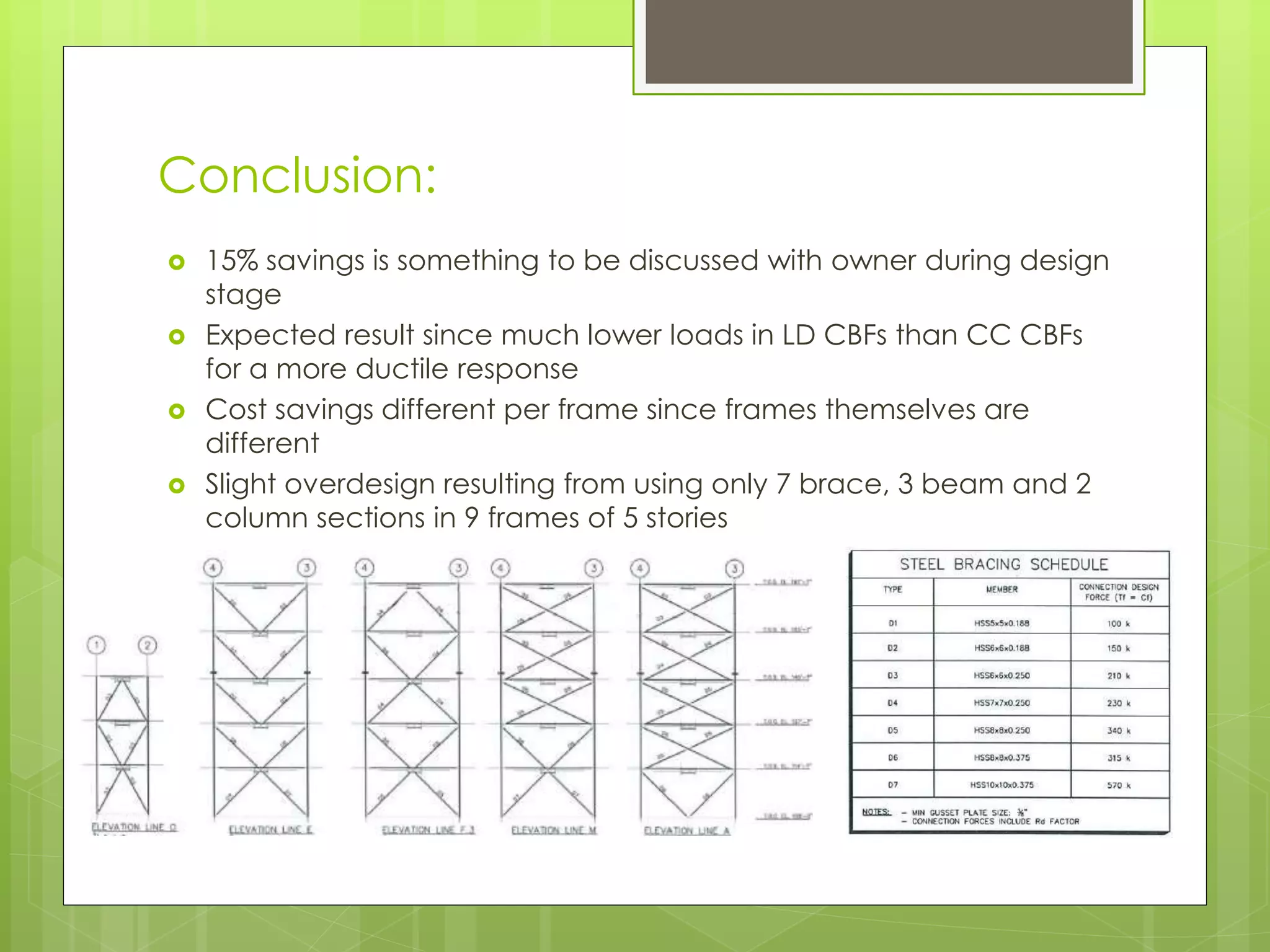
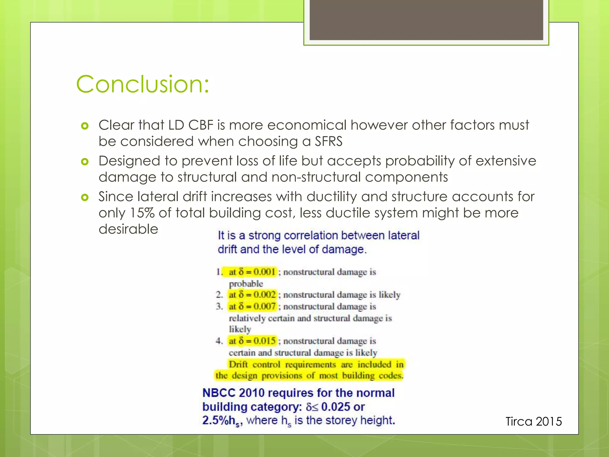
Design Proposal of a
5 Storey Steel
Building with Cost
Analysis
Michael Masi
ID: 7737157
Julian Nini
ID: 9770887
ADVANCED STEEL
STRUCTURES DESIGN
(CIVI 691C)
Project Description:
 Existing 5 Storey Steel
Commercial Building
 Montreal, Site Class C
 Rectangular
 Surface Area of 3468 m2
 Designed using
Conventional Construction
 Re-design based on Limited
Ductility
 Cost Analysis
Calculation of Seismic Loads:
 Spectral acceleration ordinates are provided by the NBCC
 Return period of 1:2500 years
 Tabulated for T = 0.2, 0.5, 1.0 and 2.0s
 Depends on earthquake history, proximity to potential earthquake
hypocentres, soil conditions, etc.
 ‘Life safety’ objective
Spectral Acceleration:
NBCC 2005
Calculation of Seismic Loads:
 Converts dynamic earthquake motion to equivalent static loading
if conditions are met
 Base shear:
Equivalent Static Force Procedure (ESFP):
NBCC 2010
𝑉 =
𝑆 𝑇𝑎 𝑀𝑣 𝐼 𝐸 𝑊
𝑅 𝑑 𝑅 𝑜
S(Ta) = Design spectral response acceleration
Ta = Fundamental lateral period of vibration
Mv = Factor accounting for higher mode vibration effects
IE = Importance factor
W = Seismic weight
Rd = Ductility related seismic force modification factor
Ro = Overstrength related seismic force modification factor
Calculation of Seismic Loads:
 Depends solely on building height
 h = 20.73 m → Ta = 0.518s
 Period can be doubled if proven through dynamic analysis
Fundamental Period of Vibration (Ta):
Calculation of Seismic Loads:
 Low Importance: IE = 0.8
 Normal Importance: IE = 1.0
 High Importance: IE = 1.3
 Post-Disaster: IE = 1.5
 Requires buildings of higher importance to:
 resist higher loads
 be less reliant on inelastic behaviour of structural elements
 have a greater reserve capacity for ground motions exceeding
design level
Importance of the Building (IE):
NBCC 2010
Calculation of Seismic Loads:
 1D + 0.25S + Cladding
Weight of the Building (W):
Calculation of Seismic Loads:
 Rd accounts for ductility
 Ro accounts for overstrength
 Structure is designed to dissipate ground motion through inelastic
deformations of the SFRS
 Degree of ductility depends on structural system chosen
 Overstrength exists since structural elements have factored
resistances, a limited selection and material properties (i.e. Fy)
higher than the minimum specified values
Seismic Force Modification Factors (Rd, Ro):
NBCC 2010
Calculation of Seismic Loads:
Seismic Force Modification Factors (Rd, Ro):
NBCC 2010
Calculation of Seismic Loads:
 Seismic forces are distributed in proportion with storey height since
first mode dominates response of the structure
 Ft is added at the top of the building to account for whipping
action from higher mode effects
 Torsional effects were considered because of type 7 irregularities
Base Shear:
𝑉 =
𝑆 𝑇𝑎 𝑀𝑣 𝐼 𝐸 𝑊
𝑅 𝑑 𝑅 𝑜
Design of Structural Components:
 Braces should yield in tension and have a controlled buckling or
yielding mode in compression, bending or shear
 All other members should be sufficiently strong for gravity loads
and fuse elements to dissipate energy
 Not required for conventional construction since they are
designed for much higher loads
 Required for limited ductile and probable resistance must be
estimated including tensile yielding, buckling and post buckling
strength
Capacity Design:
Elements of Earth. Eng. and Strct. Dynamics , by Filiatrault et al. 3rd ed
Design of Structural Components:
 Non-seismic design: higher yield strength → safer structures
 Seismic design: higher yield strength → prevents fuse from yielding
and overloads adjacent components
 Probable yield stress: RyFy
 Ry = 1.1 but RyFy ≥ 460 MPa for HSS sections
≥ 385 MPa for all other sections
Design of Braces:
Existing CC CBF Proposed LD CBF
Design of Structural Components:
 Supports gravity loads while redistributing loads due to brace
buckling and yielding
 Case 1: Cu in compression braces + Tu in tension braces
 Case 2: C’u in compression braces + Tu in tension braces
Design of Braced Beams:
Existing CC CBF Proposed LD CBF
W410X54
W410X54
W410X54
W410X54
W410X54
W360X33
W360X33
W360X33
W360X45
W360X33
Design of Structural Components:
 Vertical component of brace forces from higher stories must be
considered
 Probability of all braces reaching their capacity decreases as
number of levels considered increases
 Case 1: All braces reach Cu, Tu
 Case 2: All braces reach Cf due to 1.0E + 1.0D + 0.5L + 0.25S, where
Rd = 1 and RdRo = 1.3
Design of Braced Columns:
Existing CC CBF Proposed LD CBF
W310X86W310X129
W310X86W310X129
W250X73W310X158
W250X73W310X158
Design of Structural Components:
Design Summary:
Existing CC CBF Proposed LD CBF
W410X54
W410X54
W410X54
W410X54
W410X54
W360X33
W360X33
W360X33
W360X45
W360X33
W310X86W310X129
W310X86W310X129
W250X73W310X158
W250X73W310X158
Cost Analysis:
 $1.65/kg assumed for structural steel
 Density of 7,850 kg/m3
Conclusion:
 15% savings is something to be discussed with owner during design
stage
 Expected result since much lower loads in LD CBFs than CC CBFs
for a more ductile response
 Cost savings different per frame since frames themselves are
different
 Slight overdesign resulting from using only 7 brace, 3 beam and 2
column sections in 9 frames of 5 stories
Conclusion:
 Clear that LD CBF is more economical however other factors must
be considered when choosing a SFRS
 Designed to prevent loss of life but accepts probability of extensive
damage to structural and non-structural components
 Since lateral drift increases with ductility and structure accounts for
only 15% of total building cost, less ductile system might be more
desirable
Tirca 2015
Thank You!

Design Proposal of a 5-Storey Steel Building with Cost Analysis

  • 1.
    Design Proposal ofa 5 Storey Steel Building with Cost Analysis Michael Masi ID: 7737157 Julian Nini ID: 9770887 ADVANCED STEEL STRUCTURES DESIGN (CIVI 691C)
  • 2.
    Project Description:  Existing5 Storey Steel Commercial Building  Montreal, Site Class C  Rectangular  Surface Area of 3468 m2  Designed using Conventional Construction  Re-design based on Limited Ductility  Cost Analysis
  • 3.
    Calculation of SeismicLoads:  Spectral acceleration ordinates are provided by the NBCC  Return period of 1:2500 years  Tabulated for T = 0.2, 0.5, 1.0 and 2.0s  Depends on earthquake history, proximity to potential earthquake hypocentres, soil conditions, etc.  ‘Life safety’ objective Spectral Acceleration: NBCC 2005
  • 4.
    Calculation of SeismicLoads:  Converts dynamic earthquake motion to equivalent static loading if conditions are met  Base shear: Equivalent Static Force Procedure (ESFP): NBCC 2010 𝑉 = 𝑆 𝑇𝑎 𝑀𝑣 𝐼 𝐸 𝑊 𝑅 𝑑 𝑅 𝑜 S(Ta) = Design spectral response acceleration Ta = Fundamental lateral period of vibration Mv = Factor accounting for higher mode vibration effects IE = Importance factor W = Seismic weight Rd = Ductility related seismic force modification factor Ro = Overstrength related seismic force modification factor
  • 5.
    Calculation of SeismicLoads:  Depends solely on building height  h = 20.73 m → Ta = 0.518s  Period can be doubled if proven through dynamic analysis Fundamental Period of Vibration (Ta):
  • 6.
    Calculation of SeismicLoads:  Low Importance: IE = 0.8  Normal Importance: IE = 1.0  High Importance: IE = 1.3  Post-Disaster: IE = 1.5  Requires buildings of higher importance to:  resist higher loads  be less reliant on inelastic behaviour of structural elements  have a greater reserve capacity for ground motions exceeding design level Importance of the Building (IE): NBCC 2010
  • 7.
    Calculation of SeismicLoads:  1D + 0.25S + Cladding Weight of the Building (W):
  • 8.
    Calculation of SeismicLoads:  Rd accounts for ductility  Ro accounts for overstrength  Structure is designed to dissipate ground motion through inelastic deformations of the SFRS  Degree of ductility depends on structural system chosen  Overstrength exists since structural elements have factored resistances, a limited selection and material properties (i.e. Fy) higher than the minimum specified values Seismic Force Modification Factors (Rd, Ro): NBCC 2010
  • 9.
    Calculation of SeismicLoads: Seismic Force Modification Factors (Rd, Ro): NBCC 2010
  • 10.
    Calculation of SeismicLoads:  Seismic forces are distributed in proportion with storey height since first mode dominates response of the structure  Ft is added at the top of the building to account for whipping action from higher mode effects  Torsional effects were considered because of type 7 irregularities Base Shear: 𝑉 = 𝑆 𝑇𝑎 𝑀𝑣 𝐼 𝐸 𝑊 𝑅 𝑑 𝑅 𝑜
  • 11.
    Design of StructuralComponents:  Braces should yield in tension and have a controlled buckling or yielding mode in compression, bending or shear  All other members should be sufficiently strong for gravity loads and fuse elements to dissipate energy  Not required for conventional construction since they are designed for much higher loads  Required for limited ductile and probable resistance must be estimated including tensile yielding, buckling and post buckling strength Capacity Design: Elements of Earth. Eng. and Strct. Dynamics , by Filiatrault et al. 3rd ed
  • 12.
    Design of StructuralComponents:  Non-seismic design: higher yield strength → safer structures  Seismic design: higher yield strength → prevents fuse from yielding and overloads adjacent components  Probable yield stress: RyFy  Ry = 1.1 but RyFy ≥ 460 MPa for HSS sections ≥ 385 MPa for all other sections Design of Braces: Existing CC CBF Proposed LD CBF
  • 13.
    Design of StructuralComponents:  Supports gravity loads while redistributing loads due to brace buckling and yielding  Case 1: Cu in compression braces + Tu in tension braces  Case 2: C’u in compression braces + Tu in tension braces Design of Braced Beams: Existing CC CBF Proposed LD CBF W410X54 W410X54 W410X54 W410X54 W410X54 W360X33 W360X33 W360X33 W360X45 W360X33
  • 14.
    Design of StructuralComponents:  Vertical component of brace forces from higher stories must be considered  Probability of all braces reaching their capacity decreases as number of levels considered increases  Case 1: All braces reach Cu, Tu  Case 2: All braces reach Cf due to 1.0E + 1.0D + 0.5L + 0.25S, where Rd = 1 and RdRo = 1.3 Design of Braced Columns: Existing CC CBF Proposed LD CBF W310X86W310X129 W310X86W310X129 W250X73W310X158 W250X73W310X158
  • 15.
    Design of StructuralComponents: Design Summary: Existing CC CBF Proposed LD CBF W410X54 W410X54 W410X54 W410X54 W410X54 W360X33 W360X33 W360X33 W360X45 W360X33 W310X86W310X129 W310X86W310X129 W250X73W310X158 W250X73W310X158
  • 16.
    Cost Analysis:  $1.65/kgassumed for structural steel  Density of 7,850 kg/m3
  • 17.
    Conclusion:  15% savingsis something to be discussed with owner during design stage  Expected result since much lower loads in LD CBFs than CC CBFs for a more ductile response  Cost savings different per frame since frames themselves are different  Slight overdesign resulting from using only 7 brace, 3 beam and 2 column sections in 9 frames of 5 stories
  • 18.
    Conclusion:  Clear thatLD CBF is more economical however other factors must be considered when choosing a SFRS  Designed to prevent loss of life but accepts probability of extensive damage to structural and non-structural components  Since lateral drift increases with ductility and structure accounts for only 15% of total building cost, less ductile system might be more desirable Tirca 2015
  • 19.