Download to read offline
![International Research Journal of Engineering and Technology (IRJET) e-ISSN: 2395-0056
Volume: 05 Issue: 03 | Mar-2018 www.irjet.net p-ISSN: 2395-0072
© 2018, IRJET | Impact Factor value: 6.171 | ISO 9001:2008 Certified Journal | Page 3072
Analysis of Diagrid Structure
Gauri Dethe1, Mayur Banagar2, Prajakta Kenjale3, Ajay Das4, Prof. Mohan Dusane5,
Prof. Kartik Prajapati6
1,2,3,4 Student, Dept. of Civil Engineering, VCET, Maharashtra, India
5,6 Professor, Dept. of Civil Engineering, VCET, Maharashtra, India
---------------------------------------------------------------------***---------------------------------------------------------------------
Abstract - Diagrid structural systems are emerging as
structurally efficient as well as architecturally significant
assemblies for tall buildings. Diagrid structures areefficientin
providing solution both in term of strength and stiffness. But
nowadays a widespread application of diagrid is used in the
large span and high rise buildings, particularly when they are
complex geometries and curved shapes. The 70 storey diagrid
structural system with different angles are modelled and
analyzed by using Etabs Software. Thecomparisonofanalyzed
results in terms of top storey displacem and storey drift is
presented here.
Key Words: Angle of Diagrids, Displacement, Storey drift,
High rise building, Diagrid structural system.
1. INTRODUCTION
1.1 General
Diagrid is a design for constructing large buildingswith
steel that creates triangular structureswithdiagonalsupport
beams. It is a system of triangulated beams, straight or
curved, and horizontal rings that together make up a
structural system for a skyscraper.
The diagrid system offersseveral advantagesinaddition
to eliminating perimeter columns. Most notably it optimizes
each structural element. Typically, columns are used to
provide vertical-load-carrying capacity, and diagonals or
braces provide stability and resistance tolargeforces,suchas
wind and seismic loads. The diagonal member of the diagrid
carries both shear and moment. So the optimal angle of
placing of the diagonals is dependent of building height. The
present work is carried out using different angle by
considering different storey models. The analysis is done
using Etabs 2016 software.
In this paper we are considered four different models
which are having different angle of inclination i.e. 45°, 55°,
66°, 70°. The building dimension used is 42mX42m and total
height of the building is 238m.
Fig. -1: Plan view of the diagrid structure
Fig. -2: 3D view of diagrid model
2. MODEL DESCRIPTION
These are the geometric and structural details of the
models are as follows.
I. Plan area – 42mX42m
II. Location – Mumbai (zone-3) [wind speed – 44 m/s]
III. No. Of storey -70
IV. Storey height – 3.3m
V. Steel section – ISHB450 (for beam)
VI. Concrete:](https://image.slidesharecdn.com/irjet-v5i3725-190201112423/75/IRJET-Analysis-of-Diagrid-Structure-1-2048.jpg)
![International Research Journal of Engineering and Technology (IRJET) e-ISSN: 2395-0056
Volume: 05 Issue: 03 | Mar-2018 www.irjet.net p-ISSN: 2395-0072
© 2018, IRJET | Impact Factor value: 6.171 | ISO 9001:2008 Certified Journal | Page 3075
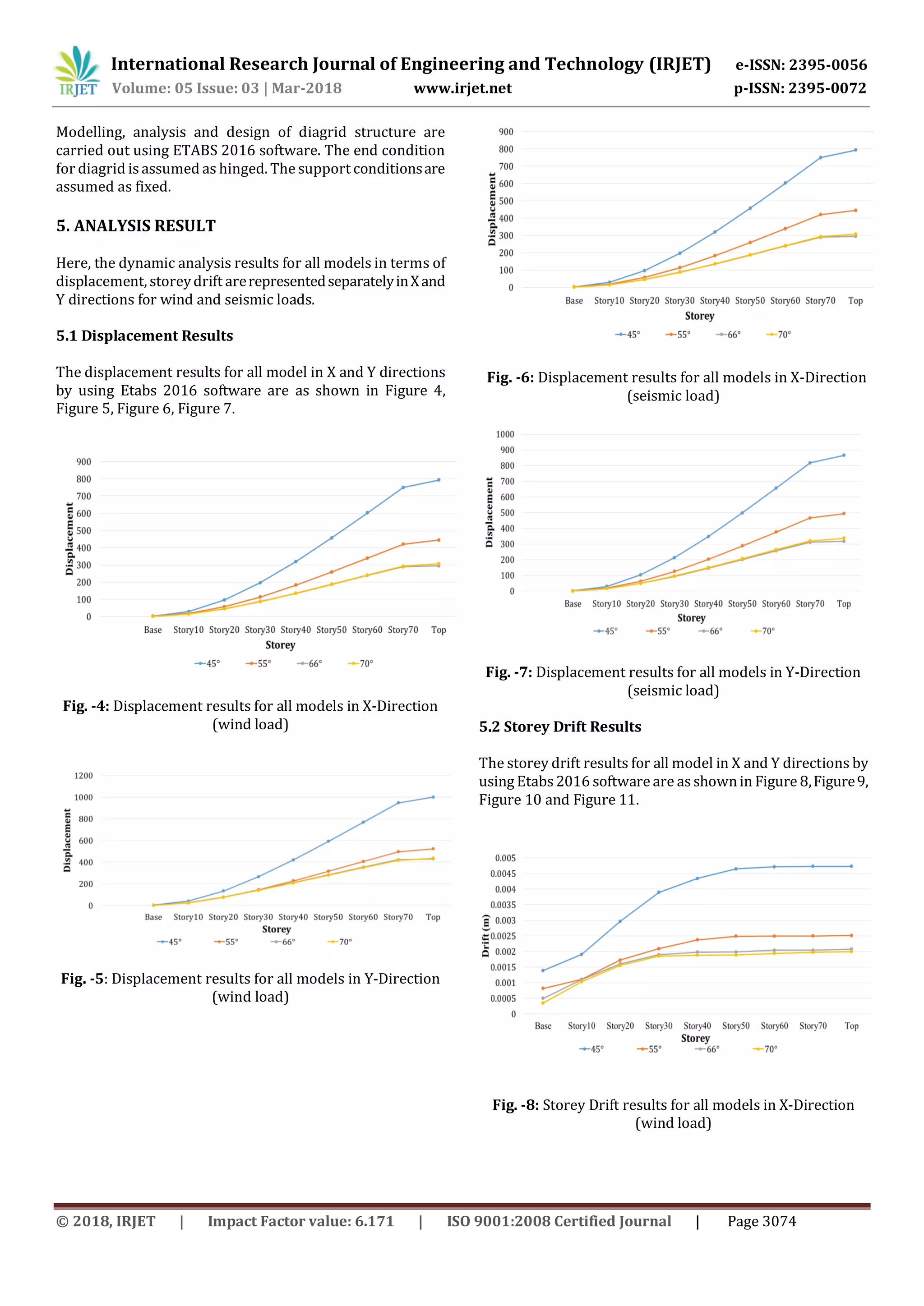
Fig. -9: Storey Drift results for all models in Y-Direction
(wind load)
Fig. -10: Storey Drift results for all models in X-Direction
(seismic load)
Fig. -11: Storey Drift results for all models in Y-Direction
(seismic load)
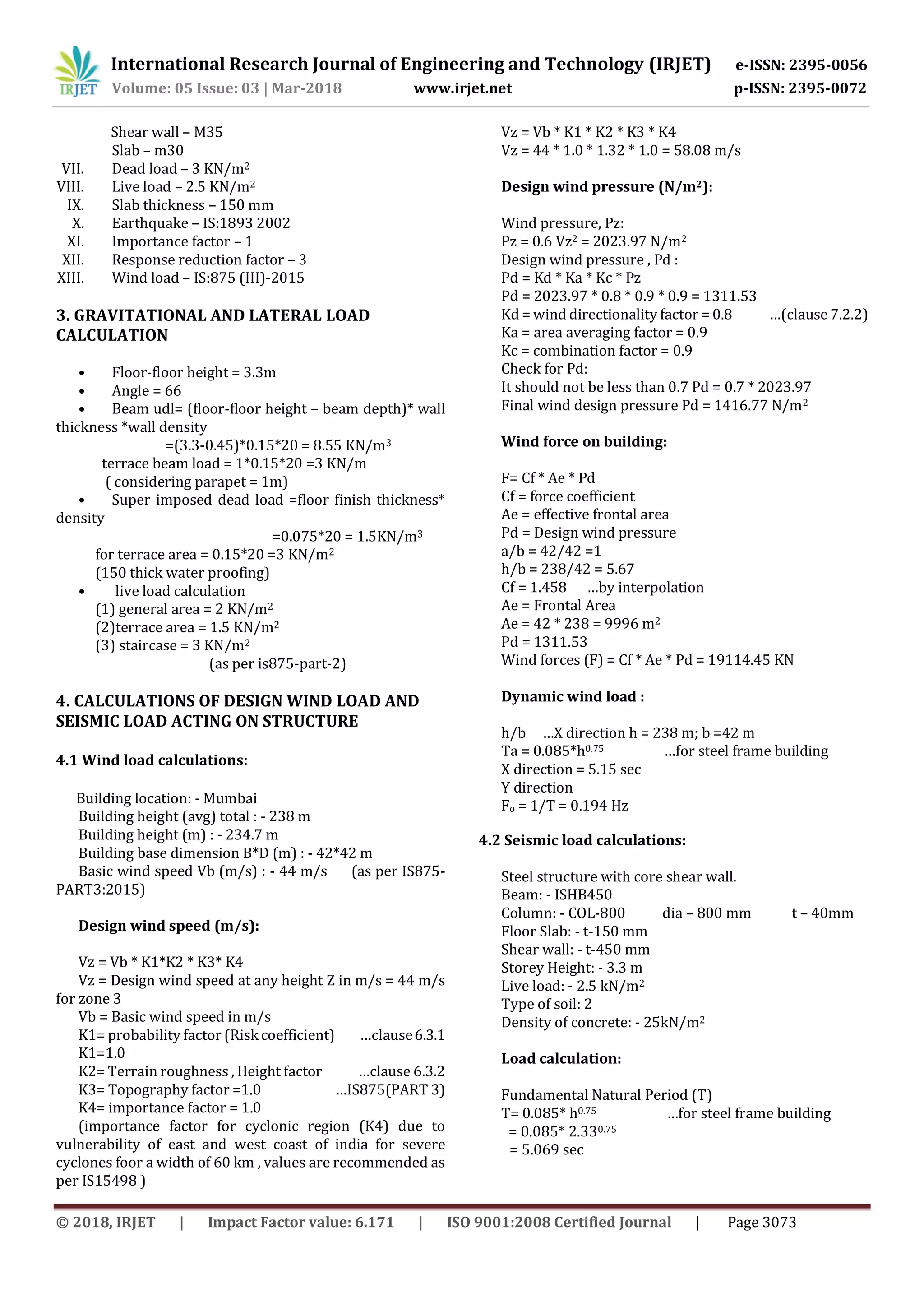
6. CONCLUSION
In this paper, comparative study is carried out by
considering different models having different angle of
inclination i.e. 45°, 55°, 66°, 70°. Diagrid angle in the region
of 66° to 70° provides more stiffnessto thediagridstructural
system which reflects the less top storey displacement. The
storey drift results are very much lesser in the region of
diagrid angle 66° to 70°. The optimal angle of diagrid is
observed as 66°. Diagrid structural system provides more
flexibility in planning interior space and facade of the
building.
ACKNOWLEDGEMENT
This study is now on completion just because of the
following people to whom which are really thanks from
depth of my heart. I feel fortunate having Prof. Mohan
Dusane, Prof. Kartik Prajapati as my guides.
REFERENCES
[1] Moon K.S., “Material-Saving Design Strategies for Tall
Building Structures", CTBUH 8thWorldCongress,Dubai,
March 2008.M. Young, The Technical Writer’s
Handbook. Mill Valley, CA: University Science, 1989.
[2] Boake, T. Understanding Steel Design: An Architectural
Design Manual (2011).
[3] IS: 1893(Part-I)-2002, Criteria for EarthquakeResistant
Design of Structures, Bureau of Indian Standard, New
Delhi.
[4] IS:875(Part-I, II, III)-1987, Code of Practice for Design
Loads (other than Earthquake) for Buildings and
Structures, Bureau of Indian Standard, New Delhi.
[5] Nishith B. Panchal, Vinubhai R. Patel, “DiagridStructural
System: Strategies to Reduce Lateral Forces on High-
Rise Buildings”, International Journal of Research in
Engineering and Technology, Volume: 03, Issue: 03,
April-2014. pp. 374-378
[6] Khushbu Jani and Paresh V. Patel, “Design of Diagrid
Structural System for High Rise Buildings as Per Indian
Standards”, Structures Congress 2013, ASCE 2013
[7] Harshita Tripathi, Dr. Sarita Singla, “Diagrid Structural
System For R.C.Framed Multi storeyed Buildings”, ISSN
2229-5518 Volume 7, Issue 6, June-2016](https://image.slidesharecdn.com/irjet-v5i3725-190201112423/75/IRJET-Analysis-of-Diagrid-Structure-4-2048.jpg)

This document analyzes the performance of different diagrid structural systems for a 70-story building with varying diagrid angles (45, 55, 66, 70 degrees). Four building models are created and analyzed using ETABS software. The results show that diagrid angles between 66-70 degrees provide greater structural stiffness, with less displacement at the top story and smaller story drifts. The optimal diagrid angle is determined to be 66 degrees, as it balances stiffness and interior space planning flexibility. The analysis contributes to understanding the behavior of diagrid structures for tall buildings.


