Download to read offline
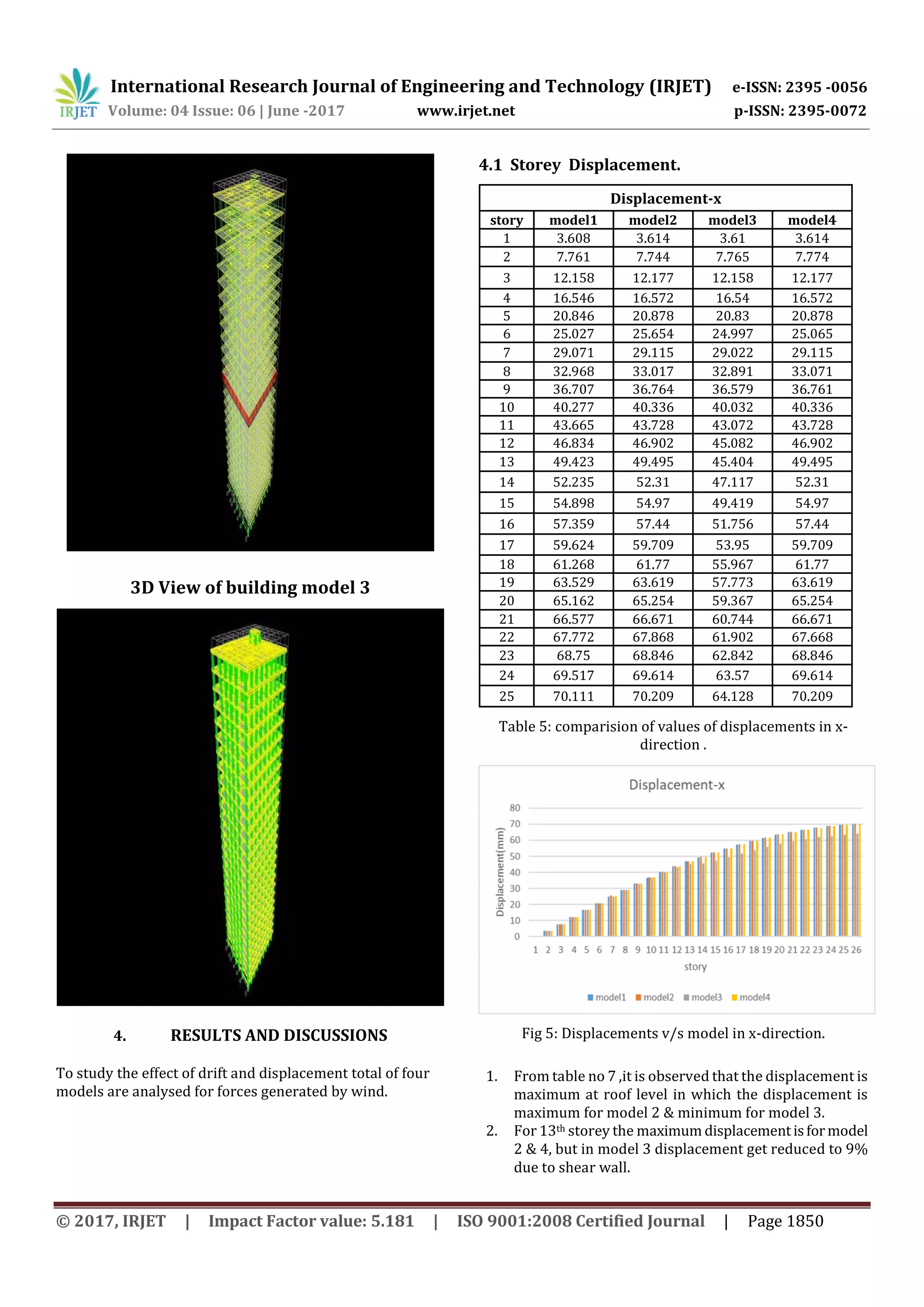
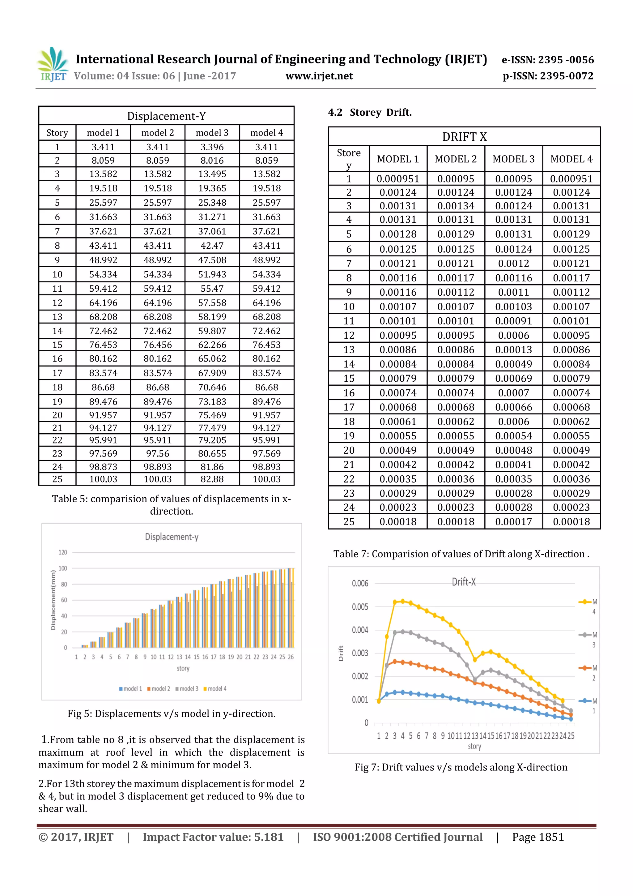
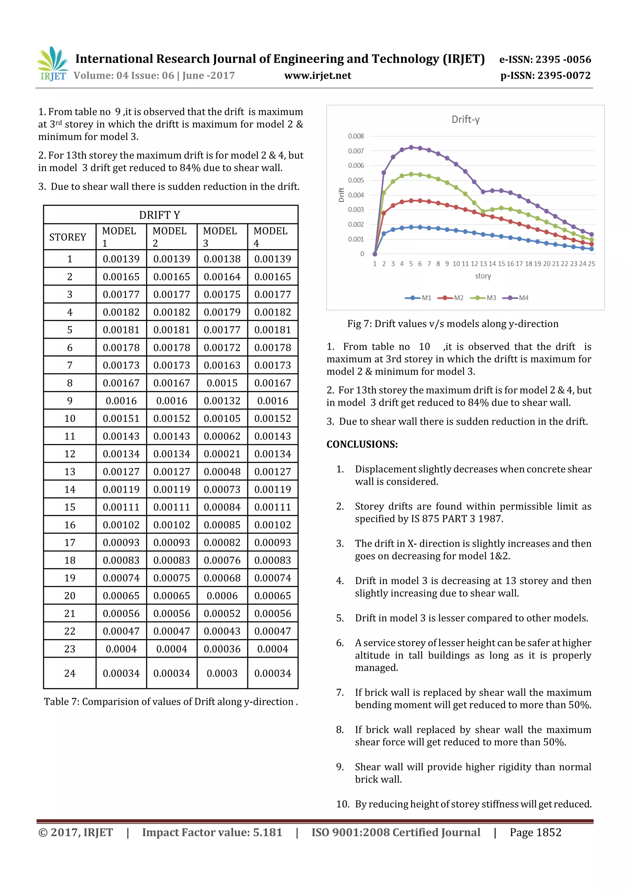

This document analyzes the structural performance of reinforced concrete framed high-rise buildings under wind loads. Four building models are considered: a baseline model, a model with an open 13th floor (soft story), a model with shear walls at the 13th floor, and a bare frame model. The models are analyzed using ETABS software to determine storey displacements and drifts. Results show the soft story model has the highest displacements, while the shear wall model reduces displacements at the 13th floor by around 9% compared to the other models. Storey drift is also highest in the soft story model. In conclusion, the analysis demonstrates how a soft story or shear walls can influence a building's response to wind loads.


