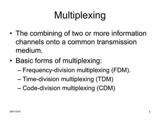
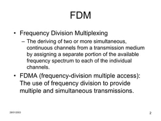
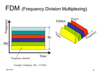
Multiplexing
• The combining of two or more information
  channels onto a common transmission
  medium.
• Basic forms of multiplexing:
       – Frequency-division multiplexing (FDM).
       – Time-division multiplexing (TDM)
       – Code-division multiplexing (CDM)


28/01/2003                                        1
FDM
   • Frequency Division Multiplexing
             – The deriving of two or more simultaneous,
               continuous channels from a transmission medium
               by assigning a separate portion of the available
               frequency spectrum to each of the individual
               channels.
   • FDMA (frequency-division multiple access):
     The use of frequency division to provide
     multiple and simultaneous transmissions.


28/01/2003                                                        2
• Transmission is organized in frequency
  channels, assigned for an exclusive use by a
  single user at a time
• If the channel is not in use, it remains idle and
  cannot be used by others
• There are channeling frequency plans
  elaborated to avoid mutual co-channel and
  adjacent-channel interference among
  neighboring stations
• The use of a radio channel or a group of radio
  channels requires authorization (license)
      – for each individual station or for group of stations


28/01/2003                                                     3
FDM (Frequency Division Multiplexing)
                                                              Power
Frequency


                                                       FDMA


                                                  Bc
Bm


                                        Time
            Frequency channel

                Example: Telephony Bm = 3-9 kHz
   28/01/2003                                                         4
FDD
• Frequency division duplexing
       – 2 radio frequency channels for each duplex
         link (1 up-link & 1 down-link or 1 forward link
         and 1 reverse link)


28/01/2003                                                 5
Transmitter Emissions
                                                                      • Transmitter output
                                                                        components
                                                                         – Fundamental (wanted)
                                                                           signal
                                                                         – Harmonic emissions
  Ideal                                                      Real
                                                                         – Master oscillator
                       1.2                                                 (fundamental & harmonics)
     Output spectrum


                        1
                                                                         – Non-harmonically related
                       0.8
                                                                           spurious
                       0.6


                       0.4
                                                                         – Noise
                       0.2


                        0
                             1   2   3   4   5   6   7   8   9   10
                                 Frequency (relative)
28/01/2003                                                                                         6
Receiver response
                                                        • Fundamental channel
                                                        • Spurious channels
                                                          – Intermediate
                                                            frequency
                                       Ideal              – Image frequency
     1.2                                                  – Channels received via
           1
                                                            LO harmonics
Response


     0.8

     0.6                                                  – Intermodulation
     0.4
                                                            channels
     0.2

           0
               1   2   3   4   5   6    7   Frequency
                                             8   9 10


28/01/2003                                                                          7
Intermodulation
• 2 or more signals, nonlinear circuit
• Intermodulation products: Fi =           CkFk
• {Ck} positive/negative integers or zero
• {Fk} frequencies of signals applied
• Order of Intermod. Product =            | C k|
• 3rd order (2F1-F2, 2F2-F1), also 5th and 7th

28/01/2003                                         8
• Non-ideal wideband linear systems are frequently
  treated by expressing the output (Y) of the system as a
  power series:
      Y      a0   a1 X        a2 X 2    a 3 X 3 ... a n X n ...
• where X is the total input signal, and the coefficients a
  are presumed to be real and independent on X.
• Assume, for simplicity, that input consists of three
  elementary signals:
     X       A(t ) cos(   1   t)   B(t ) cos(   2   t ) C(t ) cos(   3   t)

28/01/2003                                                                    9
• Some simple calculations will show that the
  output of the system Y, in addition to the linearly
  transposed input signals, contains the following
  spectral components:
• 1st order
  Multiplied version of the input signal
             a1[ A(t ) cos( 1t ) B(t ) cos(   2   t ) C (t ) cos( 3t )]


28/01/2003                                                                10
• 2nd order
• a) Distorted version of the modulating signals
             a2 2        a          a
                 A (t ); 2 B 2 (t ); 2 C 2 (t )
              2           2          2
• b) 2nd harmonics
               a2 2                 a2 2                 a2 2
                 A (t ) cos(2 1t );   B (t ) cos(2 2t );   C (t ) cos(2 3t )
               2                    2                    2
• c)         Sum and difference
             a 2 A(t ) B(t ) cos(   1   2   )t
             a 2 A(t )C (t ) cos(   2   3   )t
             a 2 B(t )C (t ) cos(   3   1   )t
28/01/2003                                                                     11
3rd order
a)   Distorted modulating signal
        3     3                  3                                                    3
          a3 A (t ) cos( 1t );     a3 B3 (t ) cos( 2t );                                a3C 3 (t ) cos( 3t )
        4                        4                                                    4
b)   3rd harmonics
        1                        1                                                    1
          a3 A3 (t ) cos(3 1t );   a3 B3 (t ) cos(3 2t );                               a3C 3 (t ) cos(3 3t )
        4                        4                                                    4
c)   Crossmodulation
             3                              3                              3
               a3 A2 (t ) B (t ) cos( 2t );   a3 A(t ) B 2 (t ) cos( 1t );   a3 A(t )C 2 (t ) cos( 1t )
             2                              2                              2
             3                              3                              3
               a3 A2 (t )C (t ) cos( 3t );    a3 B(t )C 2 (t ) cos( 2t );    a3 B 2 (t )C (t ) cos( 3t )
             2                              2                              2
d)       Intermodulation
 3                                        3                                         3
   a3 A2 (t ) B(t ) cos (   2   2   1   ;   a3 A(t ) B 2 (t ) cos (   1   2   2   ;   a3 A2 (t )C (t ) cos (   3   2   1
 4                                        4                                         4
 3                                        3                                         3
   a3 A(t )C 2 (t ) cos (   1   2   3   ;   a3 B 2 (t )C (t ) cos (   3   2   2   ;   a3 B(t )C 2 (t ) cos (   2   2   3
 4                                        4                                         4
28/01/2003                                                                                                                 12
Non-essential channels
                  F

                                Y


                                    X
28/01/2003                              13
F-D Separation Concept


28/01/2003                            14
Theoretical Cells & Cell Clusters


 Various combinations possible
28/01/2003                       15
Frequency and Distance Separation


                                              Separation acceptable
             Distance separation


                                            L+FDR=


                                   Separation unacceptable

                                                 Frequency separation
28/01/2003                                                              24
F-D Separation: 1D (Line)

             1       2   1       2       1   2

             Separation by (reuse distance) 1 zone                 2 channels


       1         2       3   1       2       3   1
                                                     2 zones   3 channels

                     n zones                 (n +1) channels
28/01/2003                                                              25
F-D Separation: 2D (Surface)


Reuse distance = 1   4 channels   Reuse distance = 2   9 channels


             n zones        (n +1)2 channels
    2
28/01/2003                                                          26
Cell clusters
                                 7
                    3


 Various combinations possible
28/01/2003                           27
F-D Separation: 3D (Space)

                                                 9
                     4
                       >8                        9 > 27
                     4
                                                 9

      1 zone   8 channels
                                     2 zone   27 channels


                 n zones    (n+1)3 channels
28/01/2003                                                  28
Ideal Lattices
       • Bound-less, regular, plane lattice
       • Each station located at a node
       • All nodes occupied (no "holes")
       • All stations identical (omnidirectional)
       • Uniform propagation (no terrain
         obstacles)
       • Uniform EM environment
       • One set of channels regularly re-used

28/01/2003                                          29
Equipment deficiency: example
   Spectrum “blocked” by typical UHF-TV terrestrial
   transmitter due to receiver’s deficiencies (“FCC
       20              Taboos”)
       18                       Area * No. of channels
        No of channels denied


       16
       14
                                  ideal:         1%
       12                         co-ch:        23%
       10        Real             other:        77%
                                8
                                6
                                4
                                2       Ideal
                                0
                                    0      50    100     150     200      250   300             350
                                                Distance from transmitter, km
28/01/2003                                                                                            31
                                                                                      Dixon64
Serial-to-Parallel Converter
                                                                     OFDM


                                                    Serial-to-Parallel Converter
                                      F1 Sub-Ch 1                                  • Orthogonal Frequency Division
                                                                                     Multiplexing (OFDM)


                                                        Signal Processing
                                                                                      – The channel is split into a


                                                           Demodulation
                                      F2 Sub-Ch 2
                                                                                        number of sub-channels
                                                                                      – Each sub-channel transmits a
                                                                                        part of the original information
                                                                                      – Each sub-channel adjusted to
                                                                                        its environment (S/N)
                                                                                      – Reduces multipath & selective
                                      FN Sub-Ch N                                       fading
                                                                                      – Allows for higher speeds
           Digital                                                                    – Requires smart signal
          Modulation                                                                    processing
                                                                                      – Used in 802.11a(USA),
                                                                                        DTTB(Eu), Hyperplan(Eu),
Delogne P, Bellanger M: The Impact of Signal Processing on an                           Power Line Coms. standards.
Efficient Use of the Spectrum, Radio Science Bulletin June 1999, 23-28
LeFloch B, Alard M, Berrou C: Coded Orthogonal Frequency Division
Multiplex, Proc of IEEE June 1995, 982-996

   28/01/2003                                                                                                          32
TDM
• Time Division Multiplex: A single carrier
  frequency channel is shared by a number of
  users, one after another. Transmission is
  organized in repetitive “time-frames”. Each
  frame consists of groups of pulses - time slots.
• Each user is assigned a separate time-slot.
• TDD – Time Division Duplex provides the
  forward and reverse links in the same frequency
  channel.

28/01/2003                                       33
TDM                                 TDM               Power density

                  Time-frame
Frequency


                                  Time
            Time slot


   Example: DECT (Digital enhanced cordless phone) Frame lasts 10 ms, consists of 24 time slots (each 417 s)
 28/01/2003                                                                                                34
SDM
• Space Division Multiple Access controls
  the radiated energy for each user in space
  using directive antennas
       – Sectorized antennas
       – Adaptive antennas


28/01/2003                                 35
CDMA or SS
    • Code Division Multiple Access or Spread
      Spectrum communication techniques
             – FH: frequency hoping (frequency synthesizer controlled by pseudo-random sequence of
                numbers)

             – DS: direct sequence (pseudo-random sequence of pulses used for spreading)
             – TH: time hoping (spreading achieved by randomly spacing transmitted pulses)
             – Other techniques
                  • Hybrid combination of the above techniques (radar and other
                     applications)

                  • Random noise as carrier


28/01/2003                                                                                           36
CDMA - FH SS
Frequency


                                                   Power density

                                            CDMA
                                  Bm
                                       Bc


                                             Transmission is organized in time-
                                  Time       frequency “slots”. Each link is
            Time-frequency slot
                                             assigned a sequence of the slots,
                                             according to a specific code. Used
                                             e.g. in Bluetooth system
   28/01/2003                                                               37
DS SS communications
                     basics
  Original
information                                                     Spreading
                Original signal   Spread signal


      Propagation effects         Transmission      Unwanted signals + Noise


                                                                      Reconstructed
     De-spreading                                                      information
                                  Spread signal+   Reconstr. signal


28/01/2003                                                                            38
SS: basic characteristics
• Signal spread over a wide bandwidth >>
    minimum bandwidth necessary to transmit information
• Spreading by means of a code independent of
    the data
• Data recovered by de-spreading the signal with
    a synchronous replica of the reference code
      – TR: transmitted reference (separate data-channel and reference-channel, correlation
             detector)
      – SR: stored reference (independent generation at T & R pseudo-random identical
             waveforms, synchronization by signal received, correlation detector)
      – Other (MT: T-signal generated by pulsing a matched filter having long, pseudo-randomly
             controlled impulse response. Signal detection at R by identical filter & correlation computation)
28/01/2003                                                                                                  39
DS SS: transmitter

                    Modulator                              X                          Antenna


                   [A(t), (t)]                            [g1(t)]
                   Information

       Carrier            Modulated signal                          Spread signal
       cos( 0t)           S1(t) = A(t) cos( 0t + (t))               g1(t)S1(t)
                          band Bm Hz                                band Bc Hz
                                                                    Bc >> Bm

gi(t): pseudo-random noise (PN) spreading functions that spreads the energy of S1(t) over a bandwidth
        considerably wider than that of S1(t): ideally gi(t) gj(t) = 1 if i = j and gi(t) gj(t) = 0 if i j

 28/01/2003                                                                                          40
DS SS-receiver


                                                                  To demodulator
                                             Correlator
                                                  &
             antenna        X                 bandpass
                                                filter
        Linear
        combination                g1(t) g1(t)S1(t)
        g1(t)S1(t)       Spreading g (t) g (t)S (t)
                                    1     2    2
        g2(t)S2(t)        function …….                    S1(t)
        …….                [g1(t)] g (t) g (t)S (t)
                                    1     n    n
        gn(t)Sn(t)                 g1(t) N(t)
        N(t) (noise)               g1(t) S’(t)
        S’(t)

28/01/2003                                                                 41
SS-receiver’s Input
                                 W/Hz                     Unwanted signals
                                                          SS s.: g2(t)S2(t); …;
                                                             gn(t)Sn(t)
                                                          Other s. : S’(t)
 Wanted (spread) signal: g1(t)S1(t)                       Noise: N(t)


                                                          Hz
                                           Bc
      Signal-to-interference ratio (S/ I)in = S/ [I( )*Bc]
                                  Bc =      Input correlator bandwidth
                                  I( ) =    Average spectral power density of unwanted signals in Bc
                                  S=        Power of the wanted signal
28/01/2003                                                                                             42
SS-correlator/ filter output
Wanted (correlated) signal: de-spread to its original bandwidth
         as g1(t) g1(t)S1(t) = S1(t) with g1(t) g1(t) = 1

                Bm                      Uncorrelated (unwanted) signals
                                     spread & rejected by correlator + noise
                                     g1(t) S’(t); g1(t) N(t); g1(t) gj(t)Sj(t) = 0
                                                         as gi(t) gj(t) = 0 for i   j


                                                      Signal-to-interference ratio
                                                      (S/ I)out = S/ [I( )*Bm]
                                     Bc = Input correlator bandwidth
                                     Bm = Output filter bandwidth
                                     I( ) = Average spectral power density of unwanted signals & noise in Bm
                Bc                   S = power of the wanted signal at the correlator output


                      Spreading = reducing spectral power density
 28/01/2003                                                                                           43
SS Processing Gain =

              = [(S/ I)in/ (S/ I)out ] = ~Bc/ Bm

   Example: GPS signal
   RF bandwidth Bc ~ 2MHz               Filter bandwidth Bm ~ 100 Hz

   Processing gain ~20’000 (+43 dB)

   Input S/N = -20 dB                   (signal power = 1% of noise power)
   Output S/N = +23 dB                  (signal power = 200 x noise power)

    (GPS = Global Positioning System)
28/01/2003                                                                   44
SS systems attributes (1)
       • Low spectral density of the signal
             – LPI: low probability of intercept
             – LPPF: low probability of position fix
             – LPSE: low probability of signal exploitation
             – Privacy
             – Covert operations capabilities
             – Low interference potential


28/01/2003                                                45
SS systems attributes (2)

• AJ: anti-jamming/ anti-interference capability
• Security
• Natural cryptographic capabilities
• Multiple-user random access communications
  with selective addressing (CDMA)
• High time resolution (~1/B; multi-path suppression)


28/01/2003                                              46
Summary
• To illustrtae the nature of the multiple access techniques
  consider a number of guests at a cocktail party. The aim
  is for all the guests to hold an intelligible conversation. In
  this case the resource available is the house itself
• FDMA: each guest has a separate room to talk to their
  partner
• TDMA: everyone is in a common room and has a limited
  time slot to hold the conversation
• FH-CDMA: the guests run from room to room to talk
• DS-CDMA: everyone is in a common room talkim at the
  same time, but each pair talks in a different language


28/01/2003                                                     47
Access Control to Radio Resources
• Distributed wireless networks (e.g. packet
  radio, ad hoc networks) have no central
  control.
• Centralized wireless networks (e.g. WLAN,
  Cellular) control the use of radio channel;
  various approaches exist
• Slotted systems (e.g. TDMA) require wide
  network synchronization for use of discrete
  time slots
28/01/2003                                 48
Packet Radio Protocols


28/01/2003                            49
Packet Radio
• In packet radio access techniques, many
  user attempt to access a single channel,
  which may led to collisions.
• Protocols aim at limiting collisions
• ALOHA is the oldest, classic protocol,
  developed in 1970 in Hawaii as an
  extension of TDMA and FDMA


28/01/2003                                   50
ALOHA
• If 2 or more users transmit at the same time so that receiver
  receives more than one packet, the receiver is unable to separate
  the packets since they are not orthogonal in time (like in TDMA) or in
  frequency (like in FDMA).
• The vulnerable period is the time interval during which the packets
  are susceptible to collisions with transmissions from other users


     Transmitter 1        Packet B              Packet C

     Transmitter 2                   Packet A

                     t1                                T1+2


28/01/2003                                                            51
• In pure ALOHA, the vulnerable period is 2 packet durations. A user
  transmits whenever it has a packet to deliver. If no acknowledgment
  (ACK) is received, the user waits a random time and retransmit the
  packet. The throughput is T = Re-2R, R being the normalized channel
  traffic in Erlangs (Tmax = 0.184 at R = 0.5)

• In slotted ALOHA, time is divided into equal time slots of length
  greater than the packet duration. The users have synchronized
  clocks and transmit messages only at the beginning of a new time
  slot. This prevent partial collisions where one packet collides with a
  portion of another. The vulnerable period is only one packet
  duration. The throughput is T = Re-R (Tmax = 0.368 at R = 1)
• ALOHA protocols do not listen to the channel before transmission,
  and do not exploit information about the other users.
28/01/2003                                                             52
• Carrier Sense Multiple Access (CSMA)
  protocols base on monitoring the channel.
  If the channel is idle (no carrier is
  detected), then the user is allowed to
  transmit. Important are detection delay
  and propagation delay.
• Reservation protocols – certain packet
  slots are assigned with priority

28/01/2003                                53
References
• Coreira LM, “Wireless Flexible
  Personalized Communications”, J Wiley
• Dunlop J, Smith DG, “Telecommunication
  Engineering”, Chapman & Hall
• Reed JH, “Software Radio”, Prentice Hall
• Taub H, Shilling DL, “Principles of
  Communication Systems”, McGraw Hill

28/01/2003                                   54

Multiplexing

  • 1.
    Multiplexing • The combiningof two or more information channels onto a common transmission medium. • Basic forms of multiplexing: – Frequency-division multiplexing (FDM). – Time-division multiplexing (TDM) – Code-division multiplexing (CDM) 28/01/2003 1
  • 2.
    FDM • Frequency Division Multiplexing – The deriving of two or more simultaneous, continuous channels from a transmission medium by assigning a separate portion of the available frequency spectrum to each of the individual channels. • FDMA (frequency-division multiple access): The use of frequency division to provide multiple and simultaneous transmissions. 28/01/2003 2
  • 3.
    • Transmission isorganized in frequency channels, assigned for an exclusive use by a single user at a time • If the channel is not in use, it remains idle and cannot be used by others • There are channeling frequency plans elaborated to avoid mutual co-channel and adjacent-channel interference among neighboring stations • The use of a radio channel or a group of radio channels requires authorization (license) – for each individual station or for group of stations 28/01/2003 3
  • 4.
    FDM (Frequency DivisionMultiplexing) Power Frequency FDMA Bc Bm Time Frequency channel Example: Telephony Bm = 3-9 kHz 28/01/2003 4
  • 5.
    FDD • Frequency divisionduplexing – 2 radio frequency channels for each duplex link (1 up-link & 1 down-link or 1 forward link and 1 reverse link) 28/01/2003 5
  • 6.
    Transmitter Emissions • Transmitter output components – Fundamental (wanted) signal – Harmonic emissions Ideal Real – Master oscillator 1.2 (fundamental & harmonics) Output spectrum 1 – Non-harmonically related 0.8 spurious 0.6 0.4 – Noise 0.2 0 1 2 3 4 5 6 7 8 9 10 Frequency (relative) 28/01/2003 6
  • 7.
    Receiver response • Fundamental channel • Spurious channels – Intermediate frequency Ideal – Image frequency 1.2 – Channels received via 1 LO harmonics Response 0.8 0.6 – Intermodulation 0.4 channels 0.2 0 1 2 3 4 5 6 7 Frequency 8 9 10 28/01/2003 7
  • 8.
    Intermodulation • 2 ormore signals, nonlinear circuit • Intermodulation products: Fi = CkFk • {Ck} positive/negative integers or zero • {Fk} frequencies of signals applied • Order of Intermod. Product = | C k| • 3rd order (2F1-F2, 2F2-F1), also 5th and 7th 28/01/2003 8
  • 9.
    • Non-ideal widebandlinear systems are frequently treated by expressing the output (Y) of the system as a power series: Y a0 a1 X a2 X 2 a 3 X 3 ... a n X n ... • where X is the total input signal, and the coefficients a are presumed to be real and independent on X. • Assume, for simplicity, that input consists of three elementary signals: X A(t ) cos( 1 t) B(t ) cos( 2 t ) C(t ) cos( 3 t) 28/01/2003 9
  • 10.
    • Some simplecalculations will show that the output of the system Y, in addition to the linearly transposed input signals, contains the following spectral components: • 1st order Multiplied version of the input signal a1[ A(t ) cos( 1t ) B(t ) cos( 2 t ) C (t ) cos( 3t )] 28/01/2003 10
  • 11.
    • 2nd order •a) Distorted version of the modulating signals a2 2 a a A (t ); 2 B 2 (t ); 2 C 2 (t ) 2 2 2 • b) 2nd harmonics a2 2 a2 2 a2 2 A (t ) cos(2 1t ); B (t ) cos(2 2t ); C (t ) cos(2 3t ) 2 2 2 • c) Sum and difference a 2 A(t ) B(t ) cos( 1 2 )t a 2 A(t )C (t ) cos( 2 3 )t a 2 B(t )C (t ) cos( 3 1 )t 28/01/2003 11
  • 12.
    3rd order a) Distorted modulating signal 3 3 3 3 a3 A (t ) cos( 1t ); a3 B3 (t ) cos( 2t ); a3C 3 (t ) cos( 3t ) 4 4 4 b) 3rd harmonics 1 1 1 a3 A3 (t ) cos(3 1t ); a3 B3 (t ) cos(3 2t ); a3C 3 (t ) cos(3 3t ) 4 4 4 c) Crossmodulation 3 3 3 a3 A2 (t ) B (t ) cos( 2t ); a3 A(t ) B 2 (t ) cos( 1t ); a3 A(t )C 2 (t ) cos( 1t ) 2 2 2 3 3 3 a3 A2 (t )C (t ) cos( 3t ); a3 B(t )C 2 (t ) cos( 2t ); a3 B 2 (t )C (t ) cos( 3t ) 2 2 2 d) Intermodulation 3 3 3 a3 A2 (t ) B(t ) cos ( 2 2 1 ; a3 A(t ) B 2 (t ) cos ( 1 2 2 ; a3 A2 (t )C (t ) cos ( 3 2 1 4 4 4 3 3 3 a3 A(t )C 2 (t ) cos ( 1 2 3 ; a3 B 2 (t )C (t ) cos ( 3 2 2 ; a3 B(t )C 2 (t ) cos ( 2 2 3 4 4 4 28/01/2003 12
  • 13.
    Non-essential channels F Y X 28/01/2003 13
  • 14.
  • 15.
    Theoretical Cells &Cell Clusters Various combinations possible 28/01/2003 15
  • 16.
    Frequency and DistanceSeparation Separation acceptable Distance separation L+FDR= Separation unacceptable Frequency separation 28/01/2003 24
  • 17.
    F-D Separation: 1D(Line) 1 2 1 2 1 2 Separation by (reuse distance) 1 zone 2 channels 1 2 3 1 2 3 1 2 zones 3 channels n zones (n +1) channels 28/01/2003 25
  • 18.
    F-D Separation: 2D(Surface) Reuse distance = 1 4 channels Reuse distance = 2 9 channels n zones (n +1)2 channels 2 28/01/2003 26
  • 19.
    Cell clusters 7 3 Various combinations possible 28/01/2003 27
  • 20.
    F-D Separation: 3D(Space) 9 4 >8 9 > 27 4 9 1 zone 8 channels 2 zone 27 channels n zones (n+1)3 channels 28/01/2003 28
  • 21.
    Ideal Lattices • Bound-less, regular, plane lattice • Each station located at a node • All nodes occupied (no "holes") • All stations identical (omnidirectional) • Uniform propagation (no terrain obstacles) • Uniform EM environment • One set of channels regularly re-used 28/01/2003 29
  • 22.
    Equipment deficiency: example Spectrum “blocked” by typical UHF-TV terrestrial transmitter due to receiver’s deficiencies (“FCC 20 Taboos”) 18 Area * No. of channels No of channels denied 16 14 ideal: 1% 12 co-ch: 23% 10 Real other: 77% 8 6 4 2 Ideal 0 0 50 100 150 200 250 300 350 Distance from transmitter, km 28/01/2003 31 Dixon64
  • 23.
    Serial-to-Parallel Converter OFDM Serial-to-Parallel Converter F1 Sub-Ch 1 • Orthogonal Frequency Division Multiplexing (OFDM) Signal Processing – The channel is split into a Demodulation F2 Sub-Ch 2 number of sub-channels – Each sub-channel transmits a part of the original information – Each sub-channel adjusted to its environment (S/N) – Reduces multipath & selective FN Sub-Ch N fading – Allows for higher speeds Digital – Requires smart signal Modulation processing – Used in 802.11a(USA), DTTB(Eu), Hyperplan(Eu), Delogne P, Bellanger M: The Impact of Signal Processing on an Power Line Coms. standards. Efficient Use of the Spectrum, Radio Science Bulletin June 1999, 23-28 LeFloch B, Alard M, Berrou C: Coded Orthogonal Frequency Division Multiplex, Proc of IEEE June 1995, 982-996 28/01/2003 32
  • 24.
    TDM • Time DivisionMultiplex: A single carrier frequency channel is shared by a number of users, one after another. Transmission is organized in repetitive “time-frames”. Each frame consists of groups of pulses - time slots. • Each user is assigned a separate time-slot. • TDD – Time Division Duplex provides the forward and reverse links in the same frequency channel. 28/01/2003 33
  • 25.
    TDM TDM Power density Time-frame Frequency Time Time slot Example: DECT (Digital enhanced cordless phone) Frame lasts 10 ms, consists of 24 time slots (each 417 s) 28/01/2003 34
  • 26.
    SDM • Space DivisionMultiple Access controls the radiated energy for each user in space using directive antennas – Sectorized antennas – Adaptive antennas 28/01/2003 35
  • 27.
    CDMA or SS • Code Division Multiple Access or Spread Spectrum communication techniques – FH: frequency hoping (frequency synthesizer controlled by pseudo-random sequence of numbers) – DS: direct sequence (pseudo-random sequence of pulses used for spreading) – TH: time hoping (spreading achieved by randomly spacing transmitted pulses) – Other techniques • Hybrid combination of the above techniques (radar and other applications) • Random noise as carrier 28/01/2003 36
  • 28.
    CDMA - FHSS Frequency Power density CDMA Bm Bc Transmission is organized in time- Time frequency “slots”. Each link is Time-frequency slot assigned a sequence of the slots, according to a specific code. Used e.g. in Bluetooth system 28/01/2003 37
  • 29.
    DS SS communications basics Original information Spreading Original signal Spread signal Propagation effects Transmission Unwanted signals + Noise Reconstructed De-spreading information Spread signal+ Reconstr. signal 28/01/2003 38
  • 30.
    SS: basic characteristics •Signal spread over a wide bandwidth >> minimum bandwidth necessary to transmit information • Spreading by means of a code independent of the data • Data recovered by de-spreading the signal with a synchronous replica of the reference code – TR: transmitted reference (separate data-channel and reference-channel, correlation detector) – SR: stored reference (independent generation at T & R pseudo-random identical waveforms, synchronization by signal received, correlation detector) – Other (MT: T-signal generated by pulsing a matched filter having long, pseudo-randomly controlled impulse response. Signal detection at R by identical filter & correlation computation) 28/01/2003 39
  • 31.
    DS SS: transmitter Modulator X Antenna [A(t), (t)] [g1(t)] Information Carrier Modulated signal Spread signal cos( 0t) S1(t) = A(t) cos( 0t + (t)) g1(t)S1(t) band Bm Hz band Bc Hz Bc >> Bm gi(t): pseudo-random noise (PN) spreading functions that spreads the energy of S1(t) over a bandwidth considerably wider than that of S1(t): ideally gi(t) gj(t) = 1 if i = j and gi(t) gj(t) = 0 if i j 28/01/2003 40
  • 32.
    DS SS-receiver To demodulator Correlator & antenna X bandpass filter Linear combination g1(t) g1(t)S1(t) g1(t)S1(t) Spreading g (t) g (t)S (t) 1 2 2 g2(t)S2(t) function ……. S1(t) ……. [g1(t)] g (t) g (t)S (t) 1 n n gn(t)Sn(t) g1(t) N(t) N(t) (noise) g1(t) S’(t) S’(t) 28/01/2003 41
  • 33.
    SS-receiver’s Input W/Hz Unwanted signals SS s.: g2(t)S2(t); …; gn(t)Sn(t) Other s. : S’(t) Wanted (spread) signal: g1(t)S1(t) Noise: N(t) Hz Bc Signal-to-interference ratio (S/ I)in = S/ [I( )*Bc] Bc = Input correlator bandwidth I( ) = Average spectral power density of unwanted signals in Bc S= Power of the wanted signal 28/01/2003 42
  • 34.
    SS-correlator/ filter output Wanted(correlated) signal: de-spread to its original bandwidth as g1(t) g1(t)S1(t) = S1(t) with g1(t) g1(t) = 1 Bm Uncorrelated (unwanted) signals spread & rejected by correlator + noise g1(t) S’(t); g1(t) N(t); g1(t) gj(t)Sj(t) = 0 as gi(t) gj(t) = 0 for i j Signal-to-interference ratio (S/ I)out = S/ [I( )*Bm] Bc = Input correlator bandwidth Bm = Output filter bandwidth I( ) = Average spectral power density of unwanted signals & noise in Bm Bc S = power of the wanted signal at the correlator output Spreading = reducing spectral power density 28/01/2003 43
  • 35.
    SS Processing Gain= = [(S/ I)in/ (S/ I)out ] = ~Bc/ Bm Example: GPS signal RF bandwidth Bc ~ 2MHz Filter bandwidth Bm ~ 100 Hz Processing gain ~20’000 (+43 dB) Input S/N = -20 dB (signal power = 1% of noise power) Output S/N = +23 dB (signal power = 200 x noise power) (GPS = Global Positioning System) 28/01/2003 44
  • 36.
    SS systems attributes(1) • Low spectral density of the signal – LPI: low probability of intercept – LPPF: low probability of position fix – LPSE: low probability of signal exploitation – Privacy – Covert operations capabilities – Low interference potential 28/01/2003 45
  • 37.
    SS systems attributes(2) • AJ: anti-jamming/ anti-interference capability • Security • Natural cryptographic capabilities • Multiple-user random access communications with selective addressing (CDMA) • High time resolution (~1/B; multi-path suppression) 28/01/2003 46
  • 38.
    Summary • To illustrtaethe nature of the multiple access techniques consider a number of guests at a cocktail party. The aim is for all the guests to hold an intelligible conversation. In this case the resource available is the house itself • FDMA: each guest has a separate room to talk to their partner • TDMA: everyone is in a common room and has a limited time slot to hold the conversation • FH-CDMA: the guests run from room to room to talk • DS-CDMA: everyone is in a common room talkim at the same time, but each pair talks in a different language 28/01/2003 47
  • 39.
    Access Control toRadio Resources • Distributed wireless networks (e.g. packet radio, ad hoc networks) have no central control. • Centralized wireless networks (e.g. WLAN, Cellular) control the use of radio channel; various approaches exist • Slotted systems (e.g. TDMA) require wide network synchronization for use of discrete time slots 28/01/2003 48
  • 40.
  • 41.
    Packet Radio • Inpacket radio access techniques, many user attempt to access a single channel, which may led to collisions. • Protocols aim at limiting collisions • ALOHA is the oldest, classic protocol, developed in 1970 in Hawaii as an extension of TDMA and FDMA 28/01/2003 50
  • 42.
    ALOHA • If 2or more users transmit at the same time so that receiver receives more than one packet, the receiver is unable to separate the packets since they are not orthogonal in time (like in TDMA) or in frequency (like in FDMA). • The vulnerable period is the time interval during which the packets are susceptible to collisions with transmissions from other users Transmitter 1 Packet B Packet C Transmitter 2 Packet A t1 T1+2 28/01/2003 51
  • 43.
    • In pureALOHA, the vulnerable period is 2 packet durations. A user transmits whenever it has a packet to deliver. If no acknowledgment (ACK) is received, the user waits a random time and retransmit the packet. The throughput is T = Re-2R, R being the normalized channel traffic in Erlangs (Tmax = 0.184 at R = 0.5) • In slotted ALOHA, time is divided into equal time slots of length greater than the packet duration. The users have synchronized clocks and transmit messages only at the beginning of a new time slot. This prevent partial collisions where one packet collides with a portion of another. The vulnerable period is only one packet duration. The throughput is T = Re-R (Tmax = 0.368 at R = 1) • ALOHA protocols do not listen to the channel before transmission, and do not exploit information about the other users. 28/01/2003 52
  • 44.
    • Carrier SenseMultiple Access (CSMA) protocols base on monitoring the channel. If the channel is idle (no carrier is detected), then the user is allowed to transmit. Important are detection delay and propagation delay. • Reservation protocols – certain packet slots are assigned with priority 28/01/2003 53
  • 45.
    References • Coreira LM,“Wireless Flexible Personalized Communications”, J Wiley • Dunlop J, Smith DG, “Telecommunication Engineering”, Chapman & Hall • Reed JH, “Software Radio”, Prentice Hall • Taub H, Shilling DL, “Principles of Communication Systems”, McGraw Hill 28/01/2003 54