This document describes a modal analysis workshop problem to find the first five natural frequencies and mode shapes of a flat rectangular plate with fixed-free boundary conditions. It provides the model dimensions and material properties, describes generating a finite element model in MSC/Nastran with shell elements, applying boundary conditions to one edge, and performing a normal modes analysis to obtain the natural frequencies and mode shapes. The objective is to have students manually create the finite element input file to model the plate and complete the modal analysis.
Hydraulic Actuation System modeling for developmental Gas Turbine EnginePREMNATH N
This document presents a hydraulic actuation system modeling using bond graph techniques. It summarizes the modeling of a two-stage servo valve and hydraulic actuator. The key steps are:
1. The two-stage servo valve and hydraulic actuator are modeled using bond graphs. Differential equations are derived from the bond graphs.
2. The differential equations are transformed into state-space form.
3. Simulation results are analyzed for the electro-hydraulic system model under conditions of underlap and critical lap servo.
The document outlines the component modeling using bond graphs, derivation of differential equations, and state-space representations to analyze the hydraulic actuation system dynamics.
This document discusses applications of the finite element method (FEM) in three categories: equilibrium problems, eigenvalue problems, and propagation problems. It provides examples of how FEM is used across various engineering disciplines, including civil engineering structures, aircraft structures, heat conduction, geotechnics, fluid mechanics, nuclear engineering, biomechanics, mechanical design, and electromagnetics. Specific applications mentioned include static structural analysis, modal analysis, heat transfer problems, soil-structure interaction, fluid flow modeling, reactor component analysis, implant design, fracture mechanics, and electric machine modeling.
A transmission shaft supports two gears and is mounted between two bearings. The document provides the pitch circle diameters of the two gears as 900 mm and 600 mm respectively. It also provides material properties and states that ASME code factors kb and kt are 1.5 and 2.0. The question asks to determine the shaft diameter using the ASME code, taking into account that the gears are connected to the shaft by keys.
Introduction to Ansys Simulation- Global leaderAnanth Narayan
This document provides an overview of ANSYS, an engineering simulation software. It discusses that ANSYS was founded in 1970 and went public in 1996. It is used to design and test products using simulations of factors like durability, temperature, fluid flow, and electromagnetic properties. The document describes the two main ANSYS environments - APDL for analyzing structures and Workbench for finite element analysis across various systems. It provides examples of companies that use ANSYS and discusses how Nebia used ANSYS simulations to optimize its showerhead design.
1. The document defines static load, failure, material strength properties including yield strength and ultimate strength in tension and compression.
2. It describes ductile materials as deforming significantly before fracturing, while brittle materials yield very little before fracturing and have similar yield and ultimate strengths.
3. The maximum shear stress theory and distortion energy theory are introduced as failure theories used in design based on yield strength and ultimate strength respectively. Safety factors are used to avoid failure based on these theories.
This document provides an introduction and overview to using ANSYS Mechanical within the ANSYS Workbench environment. It outlines the objectives and agenda for a two-day training course covering topics such as importing geometry, meshing, applying loads and boundary conditions, and post-processing results. It also provides information on the ANSYS Workbench interface, including the toolbox, project schematic, and file management.
Experimental and numerical stress analysis of a rectangular wing structureLahiru Dilshan
Structures of an aircraft can be categorised as primary structural components and secondary structure components. Primary structure components are the components which lead to failure of the aircraft if such component is failed during the flight cycle. Secondary components are load sharing components in an aircraft but will not pave the way to catastrophic failure.
Designing aircraft structures should follow several strategies to assure safety. For that, there are three main methods used in designing and maintenance procedures. First one is the safe flight, which an aircraft component has a lifetime. That component is not used beyond that limit and should replace though it is not failed. The fail-safe method is another one that redundant systems or components are there to ensure there is another way to carry the load or do necessary control. The final one is the damage tolerance which measures the current damages are within acceptable limit and carry out the main functions until the next main maintenance process.
To determine the safety of a structure component load distribution, stress and strain variation, deflection can be used as parameters to make sure that component can withstand maximum allowable load with safety factor. There are several techniques used to get accurate results as numerical methods, Finite Element Method (FEM) and experimental methods. In the design process, those three steps are followed in an orderly manner to ensure the safety of an aircraft.
This document summarizes key concepts in vibration of single-degree-of-freedom (SDOF) systems. It discusses the generalized model of SDOF systems and provides examples. It then covers the differential equations of motion for SDOF systems using Newton's law and the energy method in the time domain. Specific examples are given for mass-spring, simple pendulum, and cantilever beam systems. Considerations for equivalent mass and stiffness of springs are also addressed.
The document provides an overview of the finite element method (FEM). It describes FEM as a numerical method for solving differential equations by subdividing a body into smaller elements and connecting nodes. The key steps of FEM include discretizing the structure into elements, numbering nodes and elements, selecting displacement functions, deriving element and global stiffness matrices, applying boundary conditions, and solving for displacements to obtain stresses and strains. FEM can handle complex geometries and loading conditions, and is widely used today for structural, heat transfer, and fluid mechanics analysis.
This document provides an overview of good practices in finite element analysis (FEA). It discusses various topics including the FEA process, analysis types, element types, mesh quality, and validation. The modern design process utilizes optimization and virtual testing with FEA earlier in the process compared to the traditional design-build-test approach. A variety of linear and nonlinear analysis types are described such as static, dynamic, and buckling analyses. The document emphasizes the importance of validation, quality assurance, and maintaining proper documentation of the FEA process.
Elastic Strain Energy due to Gradual Loading.
Elastic Strain Energy due to Sudden Loading.
Elastic Strain energy due to impact loading.
Elastic Strain Energy due to Principal Stresses.
Energy of Dilation And Distortion.
A short introduction presentation about the Basics of Finite Element Analysis. This presentation mainly represents the applications of FEA in the real time world.
1 introduction to mechanical vibrations (eng. ahmed abd el aleem amin)Ahmed Abdel-Aleem
This document provides an introduction to a course on mechanical vibrations. It includes the following key points:
- The course covers topics such as vibration of single and multi-degree of freedom systems, vibration isolation, absorbers, torsional vibration, and critical speeds.
- Vibrations are present in many aspects of life from hearing to walking to machinery. They can be either helpful or harmful depending on the situation.
- Modeling dynamic systems involves representing real systems using simple models of masses, springs, and dampers to describe their vibration behavior. Mathematical models are then derived and solved.
- Key vibration concepts that will be discussed include natural frequency, damping, harmonic motion, and vibration terminology
The document provides an overview of the modeling workflow in MSC Patran, including how to build geometry, create meshes, apply loads, materials and submit an analysis. The key steps are: 1) Import or create geometry, 2) Generate meshes on the geometry, 3) Apply loads, boundary conditions and material properties, 4) Submit the model for analysis in Nastran, and 5) Import and post-process results in Patran. Forms and menus are used at each step to build the model and perform the analysis.
The document summarizes different theories for predicting failure under static loading conditions. It discusses:
1) Failure theories for ductile materials including maximum shear stress, distortion energy, and ductile Coulomb-Mohr theories, which are based on yield.
2) Failure theories for brittle materials including maximum normal stress, brittle Coulomb-Mohr, and modified Mohr theories, which do not exhibit an identifiable yield strength.
3) Details of the maximum shear stress theory and distortion energy (Von Mises) theory for ductile materials. The distortion energy theory predicts failure when the distortion strain energy equals the energy at yield in tension.
The document summarizes the structural analysis of a culvert using finite element analysis software ANSYS. It describes the steps taken which include defining the material properties of low-carbon steel, applying appropriate loading and boundary conditions, generating a mesh, and analyzing the results to find maximum deformation and Von Mises stress. The maximum deformation occurs in the horizontal direction while the stress is concentrated at the arc of the structure. Reinforcement of the arc is recommended to improve the design.
1) A monotonic tension test subjects a specimen to increasing tensile force until fracture to obtain its stress-strain behavior. For larger strains, true stress and strain must account for changes in specimen dimensions rather than engineering stress and strain.
2) Cyclic strain-controlled testing better characterizes fatigue behavior by directly controlling and measuring strain. Hysteresis loops provide the cyclic stress-strain response.
3) The strain-life approach relates the fatigue life of notched components to the life of unnotched specimens experiencing the same strain levels. It assesses fatigue damage directly based on local strain measurements.
The document summarizes a computational fluid dynamics study of flow over clean and loaded wings using ANSYS Fluent. It describes simulating flow over an airfoil at angles from 0-20 degrees both with and without a missile model attached. The results show that boundary layer separation begins around 15 degrees for the clean wing and occurs at a lower angle for the loaded wing. However, issues with meshing prevented analysis of the loaded wing case. Increasing angle of attack was found to increase lift forces until stall occurred due to vortex shedding beyond 20 degrees.
Design involves formulating a plan to satisfy a particular need and create something with physical reality. When designing a chair, factors like purpose, intended user (adult or child), material strength and cost, aesthetics, and ergonomics must be considered. Machine design uses technical information, scientific principles, and imagination to design machines to perform specific functions with maximum economy and efficiency. This document discusses various machine design considerations and principles like types of loads, material selection, and theories of failure.
This document summarizes key concepts in mechanical vibrations and dynamics from Chapter 19 of the textbook "Vector Mechanics for Engineers: Dynamics, Ninth Edition". It discusses various topics including:
- Simple harmonic motion of particles on springs and pendulums.
- Free and forced vibrations of rigid bodies.
- Damped and undamped vibrations.
- Natural frequency, period and damping of vibrating systems.
It also includes sample problems demonstrating calculations of natural frequency, period, maximum velocity and acceleration for vibrating spring-mass systems and rigid bodies like cylinders and gears. Diagrams, equations of motion and solutions are provided.
This document provides an overview of position analysis techniques for linkages and mechanisms. It discusses coordinate systems, position and displacement concepts, and methods for graphical and algebraic position analysis. Graphical methods involve drawing the linkage to scale based on given parameters and measuring positions. Algebraic methods develop vector loop equations in terms of complex numbers and solve for unknown positions and angles. Specific techniques are presented for common linkages including fourbars, slider-cranks, and geared fivebars.
This presentation contains basic idea regarding spur gear and provides the best equations for designing of spur gear. One can Easily understand all the parameters required to design a Spur Gear
This document is a thesis submitted by Gary Hopkins to the University of Cape Town in partial fulfillment of a Bachelor of Sciences degree in Civil Engineering. The thesis investigates the post-buckling behavior of shell structures through highly non-linear analysis. It implements an elasto-plastic constitutive law within the framework of SESKA, a C++ analysis code, to model shell structures using three-dimensional continuum mechanics while avoiding simplifications of shell geometry and behavior. Simple shell structures are analyzed to gain preliminary understanding of post-buckling behavior and determine the feasibility of the methods employed for further analyses. Results will be benchmarked against other verified analyses that used specialized shell elements and visco-plastic material laws.
This document compares the linear buckling analysis of flat plates with different thicknesses. Two flat plates with thicknesses of 1mm and 5mm were modeled and analyzed using LUSAS finite element software. The results showed that thicker plates had higher buckling loads, with the 5mm plate's buckling load being over 10 times greater than the 1mm plate's load. In conclusion, a plate's thickness directly influences its buckling value, with thicker plates exhibiting higher buckling strengths.
Free Vibration Analysis of circular plates with holes and cutoutsIOSR Journals
Circular plates with holes are extensively used in mechanical components. The existence of a hole
in a circular plate results in a significant change in the natural frequencies and mode shapes of the structure.
Especially if the hole is located eccentrically, the vibration behavior of these structures is expected to deviate
significantly from that of a plate with a concentric hole. These holes usually cause the change of natural
frequency as well as the decrease of load carrying capacity. It is important to comprehend the associated effects
in the work of mechanical design or flight control of the structure. Therefore, in this study, an experimental
method to determine the modal characteristics of a plate with multiple holes and slots are used is verified by the
finite element analysis (FEA) with ANSYS. Also, the relationship between parameter variations and vibration
modes is investigated. These results can be used as guidance for the modal analysis and damage detection of a
circular plate with a hole.
The document summarizes the history of Boeing and Airbus, describes several of their aircraft models, and analyzes the trend from aluminum to composite structures on the Boeing 787 and Airbus 380. It notes that Boeing established in 1916 and produced aircraft like the B-17 and B-29 during World War II. Airbus was established in 1970. The document then describes zones of aircraft structures and the materials typically used, including aluminum, composites, and corrosion treatment methods. It provides examples of accidents investigated by Boeing and analyzes Airbus' manufacturing process and composite usage on the A380.
Numerical parametric study on interval shift variation in simo sstd technique...eSAT Journals
This document presents a parametric study on the time shift interval variation in the SIMO-SSTD technique for experimental modal analysis. The SSTD (Single Station Time Domain) technique extracts modal parameters from free decay responses without using Fourier transforms. The study investigates the accuracy of natural frequency and damping ratio results from the SSTD algorithm when using different time shift intervals between data matrices. Simulated data with known modal properties is used to calculate percentage errors for different shift intervals and noise levels. The goal is to determine the effect of time shift interval on the accuracy of the SSTD technique.
Modal and harmonic analysis of tapered composite iSRINIVASULU N V
This document presents the results of a modal and harmonic analysis of a tapered composite I-beam with its big end fixed and small end free. The natural frequencies and mode shapes are investigated for various fiber orientations in the top and bottom flanges and web of the beam, as well as different modulus ratios. The natural frequencies are found to increase with increasing fiber angle and modulus ratio. Harmonic analysis applying a 1N load at the free end shows the displacement decreases with increasing natural frequency for different fiber angles and modulus ratios.
Operational Modal Analysis Implementation on a Hybrd Composite PlateHazira Haidzir
This document discusses modal analysis techniques for predicting structural deformation in aerospace structures due to airflow. It compares experimental modal analysis (EMA), which uses artificial excitation, to operational modal analysis (OMA), which extracts modal properties from operational response only. The study implemented OMA on a composite plate using a laser vibrometer for contactless response measurement. OMA results matched an EMA analysis using impact testing, validating the technique. OMA avoids complex artificial excitation and represents actual operating conditions.
Example: Modal analysis using DIgSILENT PowerFactory. This example shows the application modal analysis with Power Factory to P.M. Anderson Test System
This document provides an overview of modal analysis, including:
1) Modal analysis determines a structure's natural frequencies, mode shapes, and mode participation factors. It is the most fundamental dynamic analysis type.
2) The main steps in a modal analysis using ANSYS are building the model, choosing analysis options such as the mode extraction method, applying boundary conditions, and solving for the modes.
3) Key concepts discussed include various mode extraction methods such as Block Lanczos, normalization of mode shapes, and ensuring mode shapes are expanded if needed for subsequent analyses.
This document summarizes the structural analysis of an office building performed using SAP2000 and ETABS models. Modal, seismic, and component analyses were conducted considering dead, live, wind, snow, and seismic loads based on Eurocode standards. Results from the SAP2000 and ETABS models are presented for modal frequencies, relative displacements under seismic loading from the Santa Monica earthquake in both horizontal directions, as well as analyses of girders, walls, stairs, ramps, and slabs.
Response Spectrum Modal Analysis of Buildings using SpreadsheetsIJMER
The document describes how to perform response spectrum modal analysis of buildings using spreadsheets. It discusses the key steps in the analysis procedure according to Indian code IS 1893-2002, including calculating modal mass, modal participation factors, design lateral forces at each floor for each mode, storey shear forces for each mode, and combining results using SRSS and CQC methods. It then presents the development of a spreadsheet tool to automate the analysis process and make it simpler to perform. The spreadsheet allows the user to input parameters like building properties, mode shapes, and performs the calculations to determine design base shear and lateral floor forces according to the specified methods.
Brake Industry and Brake Simulation
This presentation discusses the business benefits to brake system design, thermal modeling, high fidelity CFD brake cooling and brake noise.
Presentation given by Mike Hebbes, ANSYS Regional Technical Manager
April 3, 2012
Experimental analysis of circular disc with diametral slotsIAEME Publication
Discs are important structural elements in engineering application such as pressure vessel,missiles and liquid container. The turbine, brake disc and diaphragm clutch spring are the wellknown examples for the industrial application of the annular plate with radial slots. The natural frequencies of component are of great interest in the analysis for response of structures to various excitations. Annular discs are fundamental structural elements studied in ocean engineering
applications from offshore platforms to under water acoustic transducers.
This document provides instructions for performing both linear and nonlinear static and dynamic analyses of a skewed plate model in ABAQUS. It describes defining the plate geometry, material properties, and mesh for a linear elastic analysis. It then provides steps for assigning boundary conditions and loads before submitting the linear analysis job. Finally, it gives directions for modifying the model to include geometric nonlinearity and redefining the output requests for the nonlinear analysis.
This document provides an overview of finite element analysis software Abaqus and presents an example truss analysis. It describes the key stages of preprocessing, simulation, and postprocessing in Abaqus. The document also demonstrates how to build a model of a truss structure, apply loads and boundary conditions, generate a mesh, submit the job, and visualize deformed shapes and stress results.
This document provides an overview of using ANSYS to analyze a bar in tension with a central hole. It describes the steps to:
1) Create the model geometry by defining element types, material properties, and generating the bar shape with a subtracted circle for the hole.
2) Mesh the geometry and apply boundary conditions and loads.
3) Solve the model and view displacement and stress results.
The document provides instructions for programming a CNC lathe machine. It lists and describes the G codes and M codes used for preparatory functions, tool functions, and programming features. It then provides an example program for facing using various G and M codes, including rapid positioning, spindle start, coolant start, linear interpolation for facing, and precision stop. The program positions to the start point, engages the tool, orients and starts the spindle and coolant, faces to depth using a feed rate, and ends the facing operation with a precision stop.
Evaluation of Fixed Base vs. Base Isolated Building SystemsIJERD Editor
This document compares the seismic performance of a 6-story building designed with a fixed base versus one with a base isolation system. It first describes the modeling and design of the fixed base building in ETABS and manually, where story drift was found to be the controlling factor. Member sizes of C45x45 columns and B45x35 beams were determined to satisfy demands. The modeling of the isolated building in ETABS used response spectrum analysis, with lateral forces much less than the fixed base building. The same member sizes were found to satisfy the reduced demands. Manual calculations of the seismic design parameters and story drift checks are shown for both the fixed base and isolated base buildings according to codes.
This document provides step-by-step instructions for modeling, analyzing, and designing a 10-story reinforced concrete building using ETABS. It includes steps to start a new model, define material properties, member sections, loads, mass sources, design codes, meshing, load combinations, analysis options, running analysis and design, and viewing results. The objective is to demonstrate the analysis and design of the building using the UBC-97 code for static lateral forces.
This document contains a tutorial on various topics for Grade 10 mathematics, including number patterns and sequences, functions and graphs, algebra and equations, finance, analytical geometry, transformations, trigonometry, mensuration, and data handling. It provides examples and multi-part questions to practice each topic, with explanations and step-by-step workings. The document is designed to help students review and reinforce key concepts covered in Grade 10 math.
A landing gear assembly consists of various components viz. Lower side stay, Upperside stay, Locking actuators, Extension actuators, Tyres, and Locking pins to name a few. Each unit having a specific operation to deal with, in this project the main unit being studied is the lower brace. The primary objective is to analyse stresses in the element of the lower brace unit using strength of materials or RDM method and Finite Element Method (FEM) and compare both. Using the obtained data a suitable material is proposed for the component. The approach used here is to study the overall behaviour of the element by taking up each aspect, finally summing up the total effect of all the aspects in the functioning of the element.
This document summarizes the methodology used in PATRAN to model and analyze a low pressure turbine for a jet engine. Key steps included importing geometry from CATIA, applying boundary conditions like pressures and temperatures from other models, meshing surfaces and volumes, applying multi-point constraints, and generating a dataset for analysis in SAMCEF. Verification steps such as checking element qualities and boundaries were also described.
The finite element method is used to solve engineering problems involving stress analysis, heat transfer, and other fields. It involves dividing a structure into small pieces called finite elements and deriving the governing equations for each element. The element equations are assembled into a global stiffness matrix and force vector. Boundary conditions are applied and the system is solved for the unknown displacements at nodes. Results like stresses, strains, and temperatures are then determined. Key steps are discretization, deriving the element stiffness matrix, assembling the global matrix, applying boundary conditions, and solving for nodal displacements.
The document provides an introduction and roadmap to learning MATLAB for students in electronic engineering. It includes 12 chapters that cover basic MATLAB skills like working with matrices, arithmetic and logical operations, plotting, and applications in areas like signal processing and control systems. The roadmap aims to teach MATLAB programming to students within 240 microyears (approximately 7.5 months). It emphasizes that MATLAB can help engineering students learn technical topics even if they don't know how to program initially.
This document provides instructions for remote sensing image processing exercises using ENVI software. It describes how to calculate the Normalized Difference Vegetation Index (NDVI) from Landsat bands 3 and 4 to identify vegetation, convert the floating point NDVI to integer values, and perform principal component analysis (PCA) to reduce dimensionality and segregate noise. Logical operations are also demonstrated to mask non-vegetated areas in the first PCA band using an NDVI threshold. The exercises familiarize students with common image math operations and transformations.
Structural analysis "slope-deflection moethod and robot modeling comparison" ...Omar Daher
structural analysis using both manual calculations"slope deflection" and software"Robot" for a frame.Term protect solution.See
https://www.slideshare.net/OmarDaher6/cvle-312-term-project.
This document contains 10 questions each from 10 units on the topic of finite element analysis. The questions cover various fundamental concepts in FEA including finite element modeling techniques like shape functions, interpolation functions, stiffness matrices, boundary conditions etc. They also involve solving sample problems using techniques like Gauss elimination, Rayleigh-Ritz method, Galerkin's method and computing stresses, displacements, temperatures etc.
Response Surface Methodology (RSM) uses designed experiments to determine the relationship between several factors and the response. RSM builds a mathematical model to describe this relationship and then uses optimization techniques to find the ideal conditions. Common RSM designs include central composite designs, Box-Behnken designs, and factorial designs. These designs allow modeling of quadratic and interaction effects. The results of RSM experiments are then used to optimize the response through statistical techniques like multiple regression analysis.
- The workshop simulates quasi-static rolling of a thick plate using ABAQUS/Explicit and ABAQUS/Standard. A half-symmetry plane strain model of a plate and roller is used.
- In ABAQUS/Explicit, mass scaling is used to speed up the single-pass simulation. Adaptive meshing maintains mesh quality during the large deformations. Surface contact is defined between the plate and roller.
- In ABAQUS/Standard, a two-step static analysis is used: contact is first established, then the roller draws the plate in the roll pass. Solution controls account for the discontinuous contact/friction behavior.
This document provides a preliminary design for a 20-story reinforced concrete building in Los Angeles. It outlines the design process, including establishing seismic loading based on ASCE 7-05 and distributing forces. A dual structural system of concrete shear walls and special moment frames is proposed. Preliminary sizing of structural elements is presented, along with calculations for seismic base shear, story shear distribution, and building overturning moment.
This document provides a tutorial for using PLAXIS 3D software to model the settlement of a foundation in overconsolidated clay. The tutorial contains 4 cases: (1) A rigid foundation modeled with elastic elements, (2) A raft foundation with applied loads, (3) A pile-raft foundation. The tutorial guides the user through creating the geometry, generating a mesh, performing calculations, and viewing results. It also describes how to model soil layers, assign material properties, apply initial stresses, and set up plastic calculations.
This document provides a tutorial manual for using the PLAXIS 3D finite element software. It contains 7 chapters that describe various geotechnical engineering applications that can be modeled and analyzed using PLAXIS 3D. Each chapter contains step-by-step instructions on creating the geometry, generating a mesh, running calculations, and viewing the results for different example applications, including foundations, excavations, embankments, tunnels, and dynamic/earthquake analyses of structures. The first chapter provides a detailed example of modeling the settlement of different foundation types (rigid, raft, pile-raft) for a building founded in clay.
This is a course project report for an Eye End of Knuckle Joint using ANSYS. A step wise procedure of analysis is given in the report along with all the possible results. This report is a part of curriculum of the subject Finite Element Analysis (FEA) of BE Mechanical Engineering final year, University of Mumbai.
Elevate Your Nonprofit's Online Presence_ A Guide to Effective SEO Strategies...TechSoup
Whether you're new to SEO or looking to refine your existing strategies, this webinar will provide you with actionable insights and practical tips to elevate your nonprofit's online presence.
Philippine Edukasyong Pantahanan at Pangkabuhayan (EPP) CurriculumMJDuyan
(𝐓𝐋𝐄 𝟏𝟎𝟎) (𝐋𝐞𝐬𝐬𝐨𝐧 𝟏)-𝐏𝐫𝐞𝐥𝐢𝐦𝐬
𝐃𝐢𝐬𝐜𝐮𝐬𝐬 𝐭𝐡𝐞 𝐄𝐏𝐏 𝐂𝐮𝐫𝐫𝐢𝐜𝐮𝐥𝐮𝐦 𝐢𝐧 𝐭𝐡𝐞 𝐏𝐡𝐢𝐥𝐢𝐩𝐩𝐢𝐧𝐞𝐬:
- Understand the goals and objectives of the Edukasyong Pantahanan at Pangkabuhayan (EPP) curriculum, recognizing its importance in fostering practical life skills and values among students. Students will also be able to identify the key components and subjects covered, such as agriculture, home economics, industrial arts, and information and communication technology.
𝐄𝐱𝐩𝐥𝐚𝐢𝐧 𝐭𝐡𝐞 𝐍𝐚𝐭𝐮𝐫𝐞 𝐚𝐧𝐝 𝐒𝐜𝐨𝐩𝐞 𝐨𝐟 𝐚𝐧 𝐄𝐧𝐭𝐫𝐞𝐩𝐫𝐞𝐧𝐞𝐮𝐫:
-Define entrepreneurship, distinguishing it from general business activities by emphasizing its focus on innovation, risk-taking, and value creation. Students will describe the characteristics and traits of successful entrepreneurs, including their roles and responsibilities, and discuss the broader economic and social impacts of entrepreneurial activities on both local and global scales.
This presentation was provided by Racquel Jemison, Ph.D., Christina MacLaughlin, Ph.D., and Paulomi Majumder. Ph.D., all of the American Chemical Society, for the second session of NISO's 2024 Training Series "DEIA in the Scholarly Landscape." Session Two: 'Expanding Pathways to Publishing Careers,' was held June 13, 2024.
How Barcodes Can Be Leveraged Within Odoo 17Celine George
In this presentation, we will explore how barcodes can be leveraged within Odoo 17 to streamline our manufacturing processes. We will cover the configuration steps, how to utilize barcodes in different manufacturing scenarios, and the overall benefits of implementing this technology.
Leveraging Generative AI to Drive Nonprofit InnovationTechSoup
In this webinar, participants learned how to utilize Generative AI to streamline operations and elevate member engagement. Amazon Web Service experts provided a customer specific use cases and dived into low/no-code tools that are quick and easy to deploy through Amazon Web Service (AWS.)
Beyond Degrees - Empowering the Workforce in the Context of Skills-First.pptxEduSkills OECD
Iván Bornacelly, Policy Analyst at the OECD Centre for Skills, OECD, presents at the webinar 'Tackling job market gaps with a skills-first approach' on 12 June 2024
Chapter wise All Notes of First year Basic Civil Engineering.pptxDenish Jangid
Chapter wise All Notes of First year Basic Civil Engineering
Syllabus
Chapter-1
Introduction to objective, scope and outcome the subject
Chapter 2
Introduction: Scope and Specialization of Civil Engineering, Role of civil Engineer in Society, Impact of infrastructural development on economy of country.
Chapter 3
Surveying: Object Principles & Types of Surveying; Site Plans, Plans & Maps; Scales & Unit of different Measurements.
Linear Measurements: Instruments used. Linear Measurement by Tape, Ranging out Survey Lines and overcoming Obstructions; Measurements on sloping ground; Tape corrections, conventional symbols. Angular Measurements: Instruments used; Introduction to Compass Surveying, Bearings and Longitude & Latitude of a Line, Introduction to total station.
Levelling: Instrument used Object of levelling, Methods of levelling in brief, and Contour maps.
Chapter 4
Buildings: Selection of site for Buildings, Layout of Building Plan, Types of buildings, Plinth area, carpet area, floor space index, Introduction to building byelaws, concept of sun light & ventilation. Components of Buildings & their functions, Basic concept of R.C.C., Introduction to types of foundation
Chapter 5
Transportation: Introduction to Transportation Engineering; Traffic and Road Safety: Types and Characteristics of Various Modes of Transportation; Various Road Traffic Signs, Causes of Accidents and Road Safety Measures.
Chapter 6
Environmental Engineering: Environmental Pollution, Environmental Acts and Regulations, Functional Concepts of Ecology, Basics of Species, Biodiversity, Ecosystem, Hydrological Cycle; Chemical Cycles: Carbon, Nitrogen & Phosphorus; Energy Flow in Ecosystems.
Water Pollution: Water Quality standards, Introduction to Treatment & Disposal of Waste Water. Reuse and Saving of Water, Rain Water Harvesting. Solid Waste Management: Classification of Solid Waste, Collection, Transportation and Disposal of Solid. Recycling of Solid Waste: Energy Recovery, Sanitary Landfill, On-Site Sanitation. Air & Noise Pollution: Primary and Secondary air pollutants, Harmful effects of Air Pollution, Control of Air Pollution. . Noise Pollution Harmful Effects of noise pollution, control of noise pollution, Global warming & Climate Change, Ozone depletion, Greenhouse effect
Text Books:
1. Palancharmy, Basic Civil Engineering, McGraw Hill publishers.
2. Satheesh Gopi, Basic Civil Engineering, Pearson Publishers.
3. Ketki Rangwala Dalal, Essentials of Civil Engineering, Charotar Publishing House.
4. BCP, Surveying volume 1
A Visual Guide to 1 Samuel | A Tale of Two HeartsSteve Thomason
These slides walk through the story of 1 Samuel. Samuel is the last judge of Israel. The people reject God and want a king. Saul is anointed as the first king, but he is not a good king. David, the shepherd boy is anointed and Saul is envious of him. David shows honor while Saul continues to self destruct.
Level 3 NCEA - NZ: A Nation In the Making 1872 - 1900 SML.pptHenry Hollis
The History of NZ 1870-1900.
Making of a Nation.
From the NZ Wars to Liberals,
Richard Seddon, George Grey,
Social Laboratory, New Zealand,
Confiscations, Kotahitanga, Kingitanga, Parliament, Suffrage, Repudiation, Economic Change, Agriculture, Gold Mining, Timber, Flax, Sheep, Dairying,
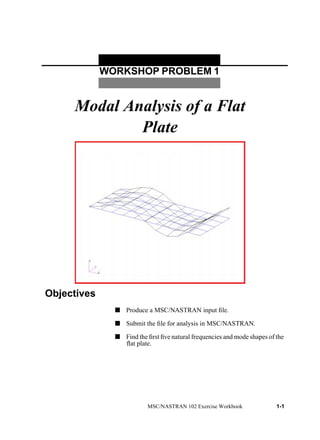
1. WORKSHOP PROBLEM 1
Modal Analysis of a Flat
Plate
MSC/NASTRAN 102 Exercise Workbook 1-1
Objectives
s Produce a MSC/NASTRAN input file.
s Submit the file for analysis in MSC/NASTRAN.
s Find the first five natural frequencies and mode shapes of the
flat plate.
3. WORKSHOP 1 Modal Analysis of a Flat Plate
MSC/NASTRAN 102 Exercise Workbook 1-3
Model Description:
For this example, use Lanczos method to find the first five natural
frequencies and mode shapes of a flat rectangular plate. One of the edges
is fixed, (See Figure 1.2.). Below is a finite element representation of the
rectangular plate. It also contains the geometric dimensions and the loads
and boundary constraints. Table 1.1 contains the necessary parameters to
construct the input file.
Figure 1.1-Grid Coordinates and Element Connectivities
a
b
4. 1-4 MSC/NASTRAN 102 Exercise Workbook
Figure 1.2-Loads and Boundary Conditions
Table 1.1
Length (a) 5 in
Height (b) 2 in
Thickness 0.100 in
Weight Density 0.282 lbs/in3
Mass/Weight Factor 2.59E-3 sec2/in
Elastic Modulus 30.0E6 lbs/in2
Poisson’s Ratio 0.3
5. WORKSHOP 1 Modal Analysis of a Flat Plate
MSC/NASTRAN 102 Exercise Workbook 1-5
Natural Frequency: Hertz
where i= 1,2,3, ...
j= 1,2,3, ...
Description: Clamped-Free-Free-Free
a = length of plate
b = width of plate
h = thickness of plate
i = number of half-waves in mode shape along horizontal axis
j = number of half-waves in mode shape along vertical axis
C = clamped edge
E = modulus of elasticity
F = free edge
S = simply supported edge
= mass per unit area of plate ( h for a plate material with density )
= Poisson ratio
f ij
λij
2
2πa
2
------------
Eh
3
12γ 1 ν
2
–( )
-----------------------------
1 2⁄
=
γ µ µ
ν
F
F
C F
a
b
7. WORKSHOP 1 Modal Analysis of a Flat Plate
MSC/NASTRAN 102 Exercise Workbook 1-7
Suggested Exercise Steps
s Explicitly generate a finite element representation of the plate
structure. (i.e., The grids (GRID) and element connectivities
(CQUAD4) should be defined manually.)
s Define material (MAT1) and element (PSHELL) properties.
s Apply the fixed boundary constraints (SPC1).
s Prepare the model for a normal modes analysis (SOL 103 and
PARAMs).
s PARAM, WTMASS, 0.00259
s PARAM, COUPMASS, 1
s Generate an input file and submit it to the MSC/NASTRAN
solver for normal modes analysis.
s Review the results, specifically the eigenvalues.
11. WORKSHOP 1 Modal Analysis of a Flat Plate
MSC/NASTRAN 102 Exercise Workbook 1-11
Exercise Procedure:
1. Users who are not utilizing MSC/PATRAN for generating an input file
should go to Step 11, otherwise, proceed to step 2.
2. Create a new database named prob1.db.
In the New Model Preference form set the following:
3. Activate the entity labels by selecting the Show Labels icon on the tool-
bar.
4. Create a surface.
File/New Database
New Database Name prob1
OK
Tolerance x Default
Analysis Code: MSC/NASTRAN
OK
x Geometry
Action: Create
Object: Surface
Method XYZ
Vector Coordinates List <5, 2, 0>
Origin Coordinates List [ 0, 0, 0]
Apply
Show Labels
12. 1-12 MSC/NASTRAN 102 Exercise Workbook
Figure 1.3-The surface should resemble the output below.
5. Create the finite element model and mesh the surface.
5a. Change the number of mesh seeds to 4 and select the right edge.
x Finite Elements
Action: Create
Object: Mesh Seed
Type: Uniform
x Number of Elements
Number = 10
Curve List
(see Figure 1.3)
Surface 1.2
Apply
Number = 4
Curve List
(see Figure 1.3)
Surface 1.3
Surface 1.2
Surface 1.3
X
Y
Z
1
2 3
4
1
X
Y
Z
13. WORKSHOP 1 Modal Analysis of a Flat Plate
MSC/NASTRAN 102 Exercise Workbook 1-13
5b. Mesh the surface.
Figure 1.4-The model should appear as below.
6. Create a set of material properties for the plate.
Apply
Action: Create
Object: Mesh
Type: Surface
Surface List Surface 1
Apply
x Materials
Action: Create
YY
14. 1-14 MSC/NASTRAN 102 Exercise Workbook
7. Define the plate thickness.
8. Apply constraints to the model.
8a. Constrain the left edge from moving through all degrees of freedom.
Object: Isotropic
Method: Manual Input
Material Name mat_1
Input Properties...
Elastic Modulus = 30.0E6
Poisson Ratio = .3
Density = .282
Apply
Cancel
x Properties
Action: Create
Dimension: 2D
Type: Shell
Property Set Name plate
Input Properties...
Material Name
(Select from Material Property Sets box.)
m:mat_1
Thickness 0.100
OK
Select Members Surface 1
Add
Apply
x Load/BC’s
Action: Create
15. WORKSHOP 1 Modal Analysis of a Flat Plate
MSC/NASTRAN 102 Exercise Workbook 1-15
Select the curve or edge icon.
Object: Displacement
Type: Nodal
New Set Name fixed
Input Data...
Translations <T1 T2 T3> <0, 0, 0>
Rotations <R1 R2 R3> <0, 0, >
Analysis Coordinate Frame Coord 0
OK
Select Application Region...
Select Geometry Entities
(see Figure 1.5)
Surface 1.1
Add
OK
Apply
Curve
16. 1-16 MSC/NASTRAN 102 Exercise Workbook
Figure 1.5
9. Run the analysis.
Before the complete input deck is generated for this analysis, a file that contains
only the model data needs to be created. This file is to be used in later workshops.
10. Now, you will generate the input file for analysis.
x Analysis
Action: Analyze
Object: Entire Model
Method Model Only
Job Name plate
Apply
x Analysis
Action: Analyze
Object: Entire Model
Method Analysis Deck
Surface 1.1
17. WORKSHOP 1 Modal Analysis of a Flat Plate
MSC/NASTRAN 102 Exercise Workbook 1-17
Under Output Requests, highlight:
SPCFORCES(SORT1,Real)=All FEM
An MSC/NASTRAN input file called prob1.bdf will be generated. The
process of translating your model into an input file is called Forward
Translation. The Forward Translation is complete when the Heartbeat
turns green. MSC/PATRAN Users should proceed to step 12.
Job Name prob1
Solution Type...
Solution Type: x NORMAL MODES
Solution Parameters...
Mass Calculation: Coupled
Data Deck Echo: Unsorted
Wt. -Mass Conversion = .00259
OK
OK
Subcase Create...
Available Subcases Default
Subcase Parameters...
Number of Desired Roots = 5
OK
Output Requests...
Delete
OK
Apply
Cancel
Apply
18. 1-18 MSC/NASTRAN 102 Exercise Workbook
Generating an input file for MSC/NASTRAN Users:
MSC/NASTRAN users can generate an input file using the data from
Table 1.1. The result should be similar to the output below.
11. MSC/NASTRAN Input File: prob1.dat
ID SEMINAR, PROB1
SOL 103
TIME 600
CEND
TITLE = NORMAL MODES EXAMPLE
ECHO = UNSORTED
SUBCASE 1
SUBTITLE= USING LANCZOS
METHOD = 1
SPC = 1
VECTOR=ALL
BEGIN BULK
PARAM COUPMASS 1
PARAM WTMASS .00259
EIGRL 1 5
PSHELL 1 1 .1 1 1
CQUAD4 1 1 1 2 13 12
=,*1,=,*1,*1,*1,*1
=8
CQUAD4 11 1 12 13 24 23
=,*1,=,*1,*1,*1,*1
=8
CQUAD4 21 1 23 24 35 34
=,*1,=,*1,*1,*1,*1
=8
CQUAD4 31 1 34 35 46 45
=,*1,=,*1,*1,*1,*1
=8
MAT1 1 3.+7 .3 .282
GRID 1 0. 0. 0.
=,*1,=,*0.5,==
=9
GRID 12 0. .5 0.
=,*1,=,*0.5,==
=9
GRID 23 0. 1. 0.
=,*1,=,*0.5,==
=9
20. 1-20 MSC/NASTRAN 102 Exercise Workbook
11a. We will also create an input file plate.bdf, which contains all
the relevant model data. This file is to be used in later
workshops.
GRID 1 0. 0. 0.
=,*1,=,*0.5,==
=9
GRID 12 0. .5 0.
=,*1,=,*0.5,==
=9
GRID 23 0. 1. 0.
=,*1,=,*0.5,==
=9
GRID 34 0. 1.5 0.
=,*1,=,*0.5,==
=9
GRID 45 0. 2. 0.
=,*1,=,*0.5,==
=9
PSHELL 1 1 .1 1 1
CQUAD4 1 1 1 2 13 12
=,*1,=,*1,*1,*1,*1
=8
CQUAD4 11 1 12 13 24 23
=,*1,=,*1,*1,*1,*1
=8
CQUAD4 21 1 23 24 35 34
=,*1,=,*1,*1,*1,*1
=8
CQUAD4 31 1 34 35 46 45
=,*1,=,*1,*1,*1,*1
=8
MAT1 1 3.+7 .3 .282
SPC1 1 12345 1 12 23 34 45
21. WORKSHOP 1 Modal Analysis of a Flat Plate
MSC/NASTRAN 102 Exercise Workbook 1-21
Submitting the input file for analysis:
12. Submit the input file to MSC/NASTRAN for analysis.
12a. To submit the MSC/PATRAN .bdf file for analysis, find an
available UNIX shell window. At the command prompt enter:
nastran prob1.bdf scr=yes. Monitor the run using the UNIX
ps command.
12b. To submit the MSC/NASTRAN .dat file for analysis, find an
available UNIX shell window. At the command prompt enter:
nastran prob1 scr=yes. Monitor the run using the UNIX ps
command.
13. When the run is completed, edit the prob1.f06 file and search for
the word FATAL. If no matches exist, search for the word
WARNING. Determine whether existing WARNING messages
indicate modeling errors.
14. While still editing prob1.f06, search for the word:
R E A L (spaces are necessary)
1st = __________Hz
2nd = __________Hz
3rd = __________Hz
4th = __________Hz
5th = __________Hz
22. 1-22 MSC/NASTRAN 102 Exercise Workbook
Comparison of Results
15. Compare the results obtained in the .f06 file with the results on
the following page:
23. WORKSHOP1ModalAnalysisofaFlatPlate
MSC/NASTRAN102ExerciseWorkbook1-23
R E A L E I G E N V A L U E S
MODE EXTRACTION EIGENVALUE RADIANS CYCLES GENERALIZED GENERALIZED
NO. ORDER MASS STIFFNESS
1 1 7.056994E+05 8.400591E+02 1.336996E+02 1.000000E+00 7.056994E+05
2 2 1.878432E+07 4.334088E+03 6.897916E+02 1.000000E+00 1.878432E+07
3 3 2.811467E+07 5.302327E+03 8.438915E+02 1.000000E+00 2.811467E+07
4 4 1.931709E+08 1.389859E+04 2.212030E+03 1.000000E+00 1.931709E+08
5 5 2.234434E+08 1.494802E+04 2.379052E+03 1.000000E+00 2.234434E+08
16. MSC/NASTRAN Users have finished this exercise. MSC/PATRAN Users should
proceed to the next step.
17. Proceed with the Reverse Translation process, that is importing the prob1.op2 results file into MSC/
PATRAN. To do this, return to the Analysis form and proceed as follows:
x Analysis
Action: Read Output2
Object: Result Entities
Method Translate
Select Results File...
Select Results File prob1.op2
OK
24. 1-24 MSC/NASTRAN 102 Exercise Workbook
To simplify the view, turn off the entity labels using the toolbar.
In addition, switch to a 3 view isometric view point.
When the translation is complete bring up the Results form.
The results should resemble Figure 1.6.
Apply
x Results
Form Type: Basic
Select Results Cases 1.1-Default, Mode 1
Select Deformation Result 1.1 Eigenvectors, Translational
Apply
Hide Labels
Iso 3 View
25. WORKSHOP 1 Modal Analysis of a Flat Plate
MSC/NASTRAN 102 Exercise Workbook 1-25
Figure 1.6
To reset the graphics, click on this icon:
Repeat the procedure to view the other mode shapes.
Quit MSC/PATRAN when you are finished with this exercise.
1
2
3
4
5 6 7 8 9 10 11
12
13
14
15
16 17 18 19 20 21 22
23
24
25
26
27
28 29 30 31 32 33
34
35
36
37
38 39 40 41 42 43 44
45
46
47
48
49 50 51 52 53 54 551
2
3
4
5 6 7 8 9 10
11
12
13
14 15 16 17 18 19 20
21
22
23
24
25 26 27 28 29 30
31
32
33
34
35 36 37 38 39 40
X
Y
Z
X
Y
Z
Reset Graphics