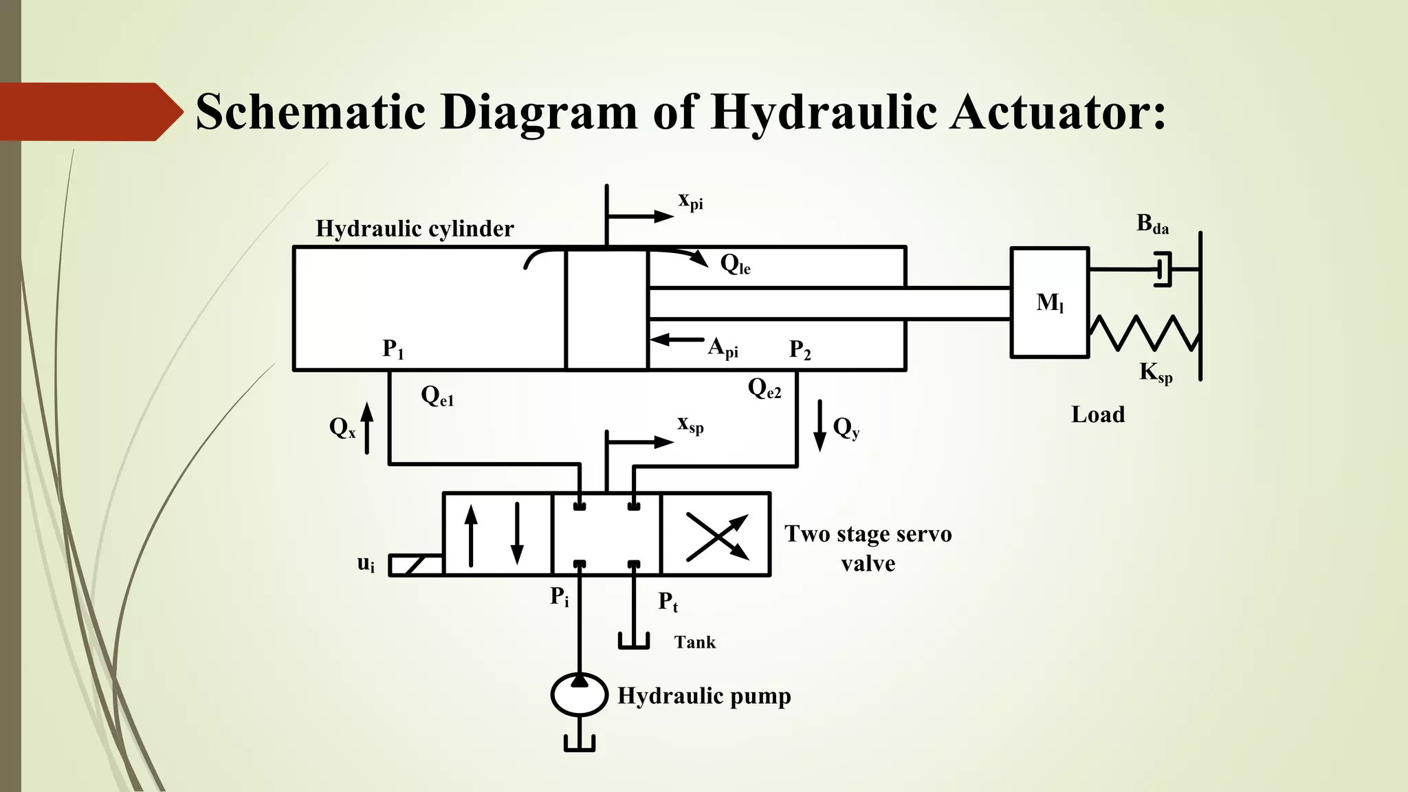
Hydraulic Actuation System
Modeling for Developmental
Gas Turbine Engine
Presented by
N . Premnath
31607104
M.tech
Instrumentation
4th Semester.
Internal Guide
Dr. Neena Jaggi
HOD, Professor
Dept of Physics
NIT Kurukushetra.
External Guide
Mr. V.G.Sanjawadmath
Scientist ‘G’.
Mr. Santhosh Muthe
Scientist ‘D’
GTRE, DRDO, Bangalore
FINAL VIVA VOCE
2016-2018
DEPARTMENT OF PHYSICS
NATIONAL INSTITUTE OF TECHNOLOGY
KURUKSHETRA
Contents:
 Introduction
 Literature Review
 Block Diagram of EHAS
 Goals
 Bond Graph Techniques
 Comparison of bond graph elements with block diagram
 Schematic Diagram of Two Stage Servo Valve
 Modeling of Two Stage Servo Valve using Bond graph
 Differential equations and State space form of Two Stage Servo Valve
 Schematic Diagram of Hydraulic Actuator
 Modeling Hydraulic Actuator using Bond graph
 Differential equations and State space form of Hydraulic Actuator
 Controller Design
 Results and Discussion
Literature Review:
Effects Result References
Oil is returned from the valve to
the tank through a low pressure
return pipe.
Simulation results show that
dynamic behavior is mainly
depends on the proper
conditions of the seals.
Richard Poley, 2005
Internal leakage and friction
forces are present in the
hydraulic cylinder
Fuzzy logical control is to
produce control signals that are
not only proportionally
dependent on control error.
B.Sulc, J.A. Jan, 2002
Friction and internal leakage
model were integrated into the
electro-hydraulic actuator
model.
Sliding mode control technique,
the nonlinearities and
uncertainties i.e. friction and
internal leakage has been fully
compensated.
M. F. Rahmat, Zulfatman,
A.R.Husain, Y. m. Sam, July
2011.
Literature Review:
Effects Result References
Excess pump fluid is discharged
to tank from relief valve and
pressure drops due to throttling
in proportional valve. This cause
waste of energy.
System uncertainties are
considered and a robust H∞
control synthesis approach is
used to control the position of
the system.
Ahsan Saeedzadeh, S. Mehdi
Rezaei, Mohammad Zareinejad
oct 2016.
Leakage flow between the spool
valve and body considerably
dominates the orifice flow
through the valve.
It should be accounted in
controller design.
Erylmaz and Wilson, 2000.
Introduction:
 An Electro-Hydraulic Actuation Systems are widely used in different industrial
application.
 It is used wherever high magnitude forces are exerted.
 It is a closed loop system which consists of Two Stage Servo Valve, double acting
hydraulic cylinder and reservoir.
 It is used to control the position of the aircraft, and etc,.
Block Diagram of EHAS:
TWO STAGE
SERVO
VALVE
HYDRAULIC
ACTUATOR
CONTROLLER
Demand
Input
(mm)
-
+
Supply Pressure
(KPa)
Input Current
for valve
is(mA)
Flow rate
(Qx) (m3
/s)
Flow rate
(Qy) (m3
/s)
Acutator
Position
(mm)
Negative Feedback
Goals:
 The Physical structure and operating principle of the Electro-Hydraulic Actuation
system are analyzed first.
 Modeled the Two Stage Servo Valve and Hydraulic Actuator using Bond Graph
Technique in presence of Underlap servo and Critical lap servo.
 Mathematical differential equations are derived from the Bond Graph of Two
Stage Servo Valve and Hydraulic Actuator.
 Generated the State Space representation from the Differential equations of the
Two Stage Servo Valve and Hydraulic Actuator.
 Analyzed the Electro-Hydraulic System model under condition of Underlap
Servo and Critical lap Servo by simulating in MATLAB/Simulink environment.
Bond Graph Technique:
 Bond Graph is the technique which is used to represent the any system in the
single graphical model.
 In Bond Graph technique, the flow of energy for the systems never change.
 The basic components of Bond Graph technique consists of ‘effort’ represented
as ‘e’, ‘flow’ indicated as ‘f’, Resistive elements as ‘R’, Capacitive elements as
‘C’, and Inertance elements as ‘I’.
 Two types of sources are available in Bond Graph, they are ‘Source effort’
indicated as ‘Se’ and ‘Source flow’ represented as ‘Sf ‘.
 There are types of junctions are available in Bond Graph, they are ‘0-Junction’
and ‘1-Junction’.
 Special bond graph element introduced in the Bond Graph technique which is the
hidden edge of the Tetron State Variables, known as ‘Memristor’.
 Resistive Element:
𝑒 = 𝑅 𝑓
𝑓 =
1
𝑅
𝑒
 Inertial Element:
𝑓 =
1
𝐼
𝑒 𝑑𝑡
𝑒 = 𝐼 𝑓
R
e
f
R
f
e
I
f
e
I
f
e
 Capacitance Element:
𝑒 =
1
𝐶
𝑓
𝑒 =
1
𝐶
𝑓 𝑑𝑡
 Transformer Element:
𝑒2 = 𝑛 𝑒1, 𝑓1 = 𝑛 𝑓2
 Gyrator Element:
𝑒1 = 𝑟 𝑓2, 𝑒2 = 𝑟 𝑓1
C
f
e
C
f
e
TF
e1
f1
e2
f2
n
e2
f2
GY
f1
e1
r
 0 Junction:
𝑒3 = 𝑒1 = 𝑒2
𝑓3 = 𝑓1 − 𝑓2
 1 Junction:
𝑓1 = 𝑓2 = 𝑓3
𝑒3 = 𝑒1 − 𝑒2
 Source effort:
 Source flow:
0
e1
f1
e2
f2
e3f3
f2
e2
1
f1
e1
f3 e3
e
f
Seea:
e
f
Sffa:
Special Elements:
 The memristor, is proposed as a new bond graph element, on an equal footing
with R, L and C, and having some unique modeling capabilities for nonlinear
systems.
 If the resistance value can be controlled by an external signal,
the resistor is named as a Modulated Resistor, in mnemonic represented as MR.
 There should be dynamic change in the resistive either charge or impulse
controlled, when the momentum and displacement change. This has been
represented as the ‘Memristor’.
C
I ∫dt
∫dt
e
f
p q
R
Memristor
Tetron of state with memristor
Momentum
Displacement
p = ∫e dt
q = ∫f dt
Displacement vs Momentum
Comparison of bond graph elements with
block diagram:
I
I
C
f
e
f
e
f
e
R
e
f
R
f
e
f2
e2
1
f1
e1
f3 e3
0
e1
f1
e2
f2
e3f3
C
f
e
GY
e1
f1 f2
e2
r
e2
f2
GY
f1
e1
r
f2
e2
TF
f1
e1
n
TF
e1
f1
e2
f2
n
R ef
1/R ef
1/C ef
C ef
I ef
1/I ef
1/n e2e1
1/nf1 f2
n e2e1
nf1 f2
r e2f1
re1 f2
1/r e2f1
1/re1 f2
e1
e3
e2
f1
f3
f2
+
-
+
-
f1 f2
f3
e1 e2
e3
Bond Graph Block Diagram Bond Graph Block Diagram
Schematic Diagram of Two Stage Servo
Valve:
Qx Qy
PBPA
Pln Prn
θfl
QnrQnl
PiPi
PiPi
Pt
Stage 1
Stage 2
xsp
Torque
Motor
Flapper
Nozzle
Spool
Qal QblQlfe Qlre
Moog’s Two Stage Servo Valve
Construction of Two Stage Servo Valve:
 Two Stage Servo Valve consists of two stages, First stage is Torque motor,
Flapper nozzle and the Second stage is Spool Valve.
 First Stage, the sleeve is wounded with armature coil which is placed between the
permanent magnet with an air gap.
 In Second Stage, the spool valve movement is based on the input current for the
servo valve.
 The change of the angle of flapper, which control the movement of the spool
valve and also the flow rate of servo valve.
 Small input current is control the flow rate of servo valve which happens only
Electro Hydraulic Servo Valve.
Torque motor of Two Stage Servo Valve:
N N
SS
is
is
xfl
Permanent
Magnet
b
a
 The relationship for Tmotor , Torque of the Motor for Two Stage Servo Valve [Merritt], is given by
𝑇 𝑚𝑜𝑡𝑜𝑟 = 𝐾 𝑚 θ 𝑓𝑙 + 𝐾𝑖 𝑖𝑠
Where, Tmotor = Torque of the motor
Km and Ki = Intensity control constant(Nm/A) and Rotational angle constant(Nm/rad)
θ 𝑓𝑙 = Flapper angle (rad)
is = input current (mA)
Modeled Two Stage Servo Valve using Bond
Graph:
1
1
0
TF
1/lrc
1/3Ksl
TF: lfc
Bfl
Jfl
Tmotor
TF: Anfl1/Anfl:TF
00 1 Pi
Rn
0
1 1
MR MR
Pt
1Pi
TF: Asp1/Asp:TF
1
0 1 0 1101
Pt
Pi
Pi
Port A Port B
MR MR MR MR
PA PB
msp
Qb1
Qa1
Qlfe Qlre
θfl
xsp
Rn
CnCn
PLn
PRn
Qnr
Qnl
xfl
Fsl
Bsp
.
.
.
Stage 1
Stage 2
1/Ktalt
2
θfl
.
θfl
.
θfl
. θfl
.
θfl
.
e2
e3
e4 e5
e6 Fsl
q10
Fslq9
Fsl
xsp
.
xsp
.
xsp
.xsp
.xsp
.xsp
.
xsp
. xsp
. xsp
.
e23
e22e21
e20
e19
e18
e17
e16
Qa1e24
e25 Qlfe e26 Qlre Qb1
e27
Qa1
PA PA
Qlfe Qlfe
Pt
Pt
Qlre Qlre
PB PB
Qb1
xfl
.xfl
.
xfl
. xfl
.
xfl
.e1
e9 e8
e12
e13
PRn
PRn
PLn
PLn
Qnr
Qnre10
q4
Qnl
Qnle11
q6
PLn
q8 PLn
q5
PLn q7
PRn
PRn
PRn
q3
q5
q5
Pt Pt
q3
q3
q3
e14 e15
Differential equation of Two Stage Servo
Valve:
𝜃 𝑓𝑙 =
1
𝐽 𝑓𝑙
(−𝐵𝑓𝑙 𝜃 𝑓𝑙 + 𝑙𝑟𝑐 𝐹𝑠𝑙 +
𝐾 𝑚 − 𝑙2
𝑡𝑎 𝐾𝑡𝑎
𝑙 𝑓𝑐
𝑥𝑓𝑙 − 𝑙𝑓𝑐 𝐴 𝑛 + 𝐴𝑛𝑓𝑙 ∆𝑃 + 𝐾𝑖 𝑖 𝑠)
𝐹 𝑠𝑙 = −3𝑙𝑟𝑐𝐾𝑠𝑙 𝜃 𝑓𝑙 + 3𝐾𝑠𝑙 𝑥 𝑠𝑝
𝑥 𝑓𝑙 = 𝑙𝑓𝑐 𝜃 𝑓𝑙
𝑥 𝑠𝑝 = −
1
𝑚 𝑠𝑝
𝐹𝑠𝑙 −
𝐵 𝑠𝑝
𝑚 𝑠𝑝
𝑥 𝑠𝑝 +
𝐴 𝑠𝑝
𝑚 𝑠𝑝
∆𝑃 −
2 𝐴𝑖
𝑚 𝑠𝑝
𝑃𝑖
∆𝑃 = −
2 𝐴 𝑛𝑓 𝑙𝑓𝑐
𝐶 𝑛
𝜃 𝑓𝑙 −
2𝐴𝑠𝑝
𝐶 𝑛
𝑥 𝑠𝑝 −
1
𝐶 𝑛 𝑅𝑛
∆𝑃
State Space form of Two Stage Servo Valve:
𝜃 𝑓𝑙
𝐹 𝑠𝑙
𝑥 𝑓𝑙
𝑥 𝑠𝑝
∆𝑃
=
−𝐵𝑓𝑙
𝐽 𝑓𝑙
𝑙 𝑟𝑐
𝐽 𝑓𝑙
𝐾 𝑚 𝑙2
𝑡𝑎 𝐾𝑡𝑎
𝐽 𝑓𝑙
0
−𝑙𝑓𝑐 𝐴 𝑛 + 𝐴𝑛𝑓𝑙
𝐽 𝑓𝑙
−3𝑙𝑟𝑐𝐾𝑠𝑙 0 0 3𝐾𝑠𝑙 0
𝑙 𝑓𝑐 0 0 0 0
0
−1
𝑚 𝑠𝑝
0
−𝐵𝑠𝑝
𝑚 𝑠𝑝
𝐴 𝑠𝑝
𝑚 𝑠𝑝
−2 𝐴 𝑛𝑓 𝑙 𝑓𝑐
𝐶 𝑛
0 0
−2𝐴𝑠𝑝
𝐶 𝑛
−1
𝐶 𝑛 𝑅 𝑛
𝜃 𝑓𝑙
𝐹 𝑠𝑙
𝑥 𝑓𝑙
𝑥 𝑠𝑝
∆𝑃
+
𝐾𝑖
𝐽 𝑓𝑙
0
0 0
0 0
0 0
0
−2𝐴𝑖
𝑚 𝑠𝑝
𝑖 𝑠
𝑃𝑖
 The flow rates which is given as input to the actuator,
𝑄 𝑥 = 𝑐𝑑 𝑑𝑟 𝑥𝑠𝑝
2
𝑝
(𝑃𝑖 − 𝑃𝐴)
𝑄 𝑦 = 𝑐𝑑 𝑑 𝑟 𝑥𝑠𝑝
2
𝑝
(𝑃𝐵 − 𝑃𝑡)
Where, Qx and Qy = Flow rates(m3/s)
𝑝 = Density of the oil(Kg/m3)
Pi = Supply Pressure(Pa)
cd = Discharge coefficient
xsp = Position of spool (m)
PA and PB = Pressure of servovalve(Pa)
Pt = Tank Pressure(Pa)
Schematic Diagram of Hydraulic Actuator:
Pi Pt
ui
Qx Qy
Qle
P1 P2Api
xpi
xsp
Hydraulic pump
Tank
Two stage servo
valve
Hydraulic cylinder
Ml
Ksp
Bda
Load
Qe1
Qe2
Construction of Hydraulic Actuator:
 In an Electro Hydraulic Actuation System, using the Hydraulic
Actuator to control the position of aircraft.
 Double Acting Cylinder used as the Hydraulic Actuator.
 The double acting cylinder consists of piston which is controlled by
the difference of the pressures across it.
 The piston is used to control the constant load.
 The flow from the servo valve is used to adjust the piston of the
double acting cylinder in Hydraulic actuator.
Modeled Hydraulic Actuator using Bond
Graph:
0
TF
1
TF
0
1
1
1
1 1/Ksp
Ml
Bda
mr
Ff
Rle1
Rle2
Cp1
Cp2
P1
P2
Rin
Qx
Qy
Api
1/Api
P1
P1
P1
P3
P2
P2
P2
P4
P1-P2
P1
P2
F1
F2
F3
F
F4
F5
F6
xpi
.
xpi
.
xpi
.
xpi
.
xpi
.
xpi
.xpi
.
xpi
.
Ff
q7
q7
q2
q3
q1
q3
q6 q8
q8
q3
q4
Differential Equations of Hydraulic Actuator:
𝑃1 = −
1
𝑅𝑖𝑛
+
1
𝑅𝑙𝑒1
1
𝐶 𝑝1
𝑃1 +
1
𝑅𝑖𝑛 𝐶𝑝1
𝑃2 −
𝐴 𝑝𝑖
𝐶 𝑝𝑖
𝑥 𝑝𝑖
𝑃2 = −
1
𝑅𝑖𝑛 𝐶 𝑝1
𝑃1 −
1
𝑅𝑖𝑛
+
1
𝑅𝑙𝑒2
1
𝐶𝑝2
𝑃2 +
𝐴 𝑝𝑖
𝐶 𝑝𝑖
𝑥 𝑝𝑖
𝑥 𝑝𝑖 =
𝐴 𝑝𝑖
𝑀𝑙
+𝑚𝑟
𝑃1 −
𝐴 𝑝𝑖
𝑀𝑙
+𝑚𝑟
𝑃2 +
𝐵 𝑑𝑎
𝑀𝑙
+𝑚𝑟
𝑥 𝑝𝑖 −
1
𝑀𝑙
+𝑚𝑟
𝐹 𝑓
Where, 𝐶 𝑝1 =
𝑉 𝑜
+ 𝑥 𝑝𝑖
β 𝑜
and 𝐶 𝑝2 =
𝑉 𝑜
− 𝑥 𝑝𝑖
β 𝑜
Vo= Volume of the hydraulic fluid, the piston at the position of middle (m3)
βo = Bulk modulus of the hydraulic fluid (Nm2)
xpi = Displacement of the actuator (m)
Differential Equations of Hydraulic Actuator:
State Space form of Hydraulic Actuator:
𝑃1
𝑃2
𝑥 𝑝𝑖
=
−(
1
𝑅𝑖𝑛
+
1
𝑅𝑙𝑒1
)
1
𝐶 𝑝1
1
𝑅𝑖𝑛 𝐶 𝑝1
−
𝐴 𝑝𝑖
𝐶 𝑝1
1
𝑅𝑖𝑛 𝐶 𝑝2
−(
1
𝑅𝑖𝑛
+
1
𝑅𝑙𝑒2
)
1
𝐶 𝑝2
−
𝐴 𝑝𝑖
𝐶 𝑝2
𝐴 𝑝𝑖
𝑀𝑙 + 𝑚𝑟
−𝐴 𝑝𝑖
𝑀𝑙 + 𝑚𝑟
𝐵 𝑑𝑎
𝑀𝑙 + 𝑚𝑟
𝑃1
𝑃2
𝑥 𝑝𝑖
+
1
𝐶 𝑝1
0 0 0
0
−1
𝐶 𝑝2
0 0
0 0
𝐾 𝑠𝑝
𝑀𝑙
+𝑚𝑟
−1
𝑀𝑙
+𝑚𝑟
𝑄 𝑥
𝑄 𝑦
𝑥 𝑝𝑖
𝐹 𝑓
Controller Design:
 One form of Controller widely used in industrial process control is PI
controller.
 The Transfer Function of controller is ,
Gc(S) = Kpr + Kint/S
Where, Kpr = Proportional Gain
Kint = Integral Gain
 The Controller have been tuned for the Electro hydraulic actuation system,
to bring the actuator to the desired position.
 The Tuned parameter of controller is, Kpr = 0.1 mA/mm,
Kint = 0.0001mA/mm.s
Simulation Model of the Electro Hydraulic Actuation
System:
• The Sampling Time of an Electro Hydraulic Actuation System is 0.0001sec
Step Response for Closed Loop System:
Results:
Input Current for Servo Valve of Closed Loop System:
Pressure Difference across the Hydraulic Actuator under Closed Loop
System:
Flow rates of Servo Valve Under Condition of Underlapped
and Critical lapped Systems:
Open Loop Frequency of System:
Closed Loop Frequency of System:
Discussion of Results:
 Open loop and Closed loop frequency responses for system with
Critical lap and a system with Underlapped spool configuration are
obtained.
 Closed loop position response indicates, Under lapped system is
having more Overshoot than the Critical lapped system and it’s rise
time is lesser than that of the critically lapped system.
 Closed loop current response indicates, the power required for under
lapped system is more than that of the critically lapped system.
 The open loop bandwidth, closed loop bandwidth, rise time and
settling time, closed loop currents are tabulated.
Comparison Under lapped and Critically lapped Systems:
PARAMETER UNDER LAP CRITICAL LAP
Rise Time (s) 0.1399 0.3241
Settling Time (s) 6.1146 6.0413
Open loop Bandwidth
(Hz)
15.45 3.029
Closed loop Bandwidth
(Hz)
2.562 1.092
Conclusions:
 Basic bond graph elements are used in constructing the Electro Hydraulic
Actuation System.
 Two Stage Servo Valve and Hydraulic actuator are modeled separately
and two different state space representation are obtained.
 Under lapped configuration is obtained by introducing increased flow.
 Performance simulations results indicate the results are in line with
physical behavior.
Future Scope:
 Electro Hydraulic Servo Valve with overlapped spool configuration need
to be modeled with some modifications to the basic bond graph elements.
 Fidelity of the model can be enhanced considering all three configuration
namely Critical lap, Under lap and Over lap.
 Improves the Controller for the Configuration of Under lap.
References:
 H.Paynter, Analysis and Design of engineering systems, MIT Press, 1961.
 Jan F. Broenink, Introduction to Physical Systems Modelling with Bond Graph, Control
Laboratory, University of Twente.
 M.H.Toufigi, S.H.Sati, F.Najafi, Modeling and Analysis of a Mechantronic Actuator System
by using Bond Graph Methodology, IEEE 2007.
 Karnopp.D.C, Margolis.D and Rosenbergy.R, System dynamics: A unified approach, 2nd
edition, New York, Wiley 1990.
 Amalendu Mukherjee, Ranjit Karmakar, Arun Kumar Samantaray, Bond graph in
modeling, simulation and fault Identification, I.K.International.
 Javier A.Kypuros, System Dynamics and Control with Bond Graph Modeling, CRC Press.
 Chua.L, Memistor- The Missing Circuit Element, 2nd edition, New York, Wiley, 1990.
 Attila KOVARI, Influence of cylinder leakage on dynamic behavior of electrohydraulic
servo system, IEEE, 2009.
 H.E.Merrit, Hydraulic control systems, John Wiley and Sons, 1967.
 Moog’s Documentation of Two Stage Servo Valve.
 Keiwan Kashi and Dirk Soffker. Model–based estimation of force and displacement of a hydraulic cylinder.
2002.
 Berzen.W. Non linear modelling and control of hydraulic cylinders. IEEE Mediterranean Conference on
Control and Systems, 1998.
 T.H.Ho and K.K.Ahn. Design and control of a closed–loop hydraulic energy– regenerative system. 22:444–
458, 2012.
 Richard Poley. Dsp control of electro–hydraulic servo actuators. Texas Instruments Application Report,
2005.
 Muvengei.M , Kihiu.J. Bond graph modeling of interactuator interactions in multi cylinder hydraulic
system. International Journal of Aerospace and Mechanical Engineering, 5(3):147–156, 2011.
 J.Zaborszky , H.J.Harrington. A describing function for mulitiple nonlinearities present in electrohydraulic
control valves. IEEE Transcations, pages 183–190, 1957.
 P.K.C.Wang. Mathematical models for time domain design of electrohydraulic servomechanisms. IEEE
Transcations, pages 252–260, 1961.
 Nosikievic.P. Modelling and system identification. Montanex a.s, 1999.
 B. Sulc , J.A.Jan. Non linear modelling and control of hydraulic actuators. Acta Polytechnica, 42(3):41–47,
2002.
 Ilyas Istif , Ahmet Sagirifi , Kenan Kutlu. Bond graph modeling and position control of an electrohydraulic
elevator, 6th Biennial Conference on Engineering Systems Design and Analysis, pages 1–6, 2002.
Conference on Robotics and Mechatronics, pages 234– 239, 2016.
 Esmaeil Ghasemi , S.Ali Jazayeri , S.Ali A.Moosavian. Model improvement for a servovalve with force
feedback and back pressure. IEEE Transactions, 2008.
 Attila KOVARI. Influence of cylinder leakage on dynamic behavior of electrohydraulic servo system. IEEE
Transactions, pages 375–379, 2009.
 M.F.Rahmat , Zulfatman , A.R.Husain , K.Ishaque , Y.M.Sam , R.Ghazali , S.Md Rozali. Modeling and
controller design of an industrial hydraulic actuator system in the presence of friction and internal leakage.
International Journal of the Physical Sciences, 6(14):3502–3516, 2011.
 Farid Arvani , Geoff Rideout , Nick Krouglicof , Steve Butt. Bond graph modeling of a hydraulic vibration
system: Simulation and control. IMAACA, 2011.
 Damic. V , Cohodar.M , Kulenovic.M. Modeling and simulation of hydraulic systems by bond graphs.
International DAAM Symposium, 23(1):591–594 2012.
 So-Nam Yun , Jung-Ho Park , Sung-Soo Lee , Choong-Mok Yoo. Hydraulic circuit analysis for the electro
hydrostatic actuator system. International Conference on Control, Automation and Systems, pages 178–181,
2016.
 Thoma J.U. Introduction to bond graphs and their applications. Pergamon Press, Oxford., 1975.
 Liming Yu , Yudong Zhang , Hongfei Liu. Performance analysis and optimization design of dissimilar
redundant hybrid electro hydraulic actuation system. International Conference on Aircraft Utility Systems,
pages 98–104, 2016.
 Karnopp D.C. , Rosenberg R.C. System dynamics, a unified approach. John Wiley & Sons, New York.,
1975.
THANK YOU

Hydraulic Actuation System modeling for developmental Gas Turbine Engine

  • 1.
    Hydraulic Actuation System Modelingfor Developmental Gas Turbine Engine Presented by N . Premnath 31607104 M.tech Instrumentation 4th Semester. Internal Guide Dr. Neena Jaggi HOD, Professor Dept of Physics NIT Kurukushetra. External Guide Mr. V.G.Sanjawadmath Scientist ‘G’. Mr. Santhosh Muthe Scientist ‘D’ GTRE, DRDO, Bangalore FINAL VIVA VOCE 2016-2018 DEPARTMENT OF PHYSICS NATIONAL INSTITUTE OF TECHNOLOGY KURUKSHETRA
  • 2.
    Contents:  Introduction  LiteratureReview  Block Diagram of EHAS  Goals  Bond Graph Techniques  Comparison of bond graph elements with block diagram  Schematic Diagram of Two Stage Servo Valve  Modeling of Two Stage Servo Valve using Bond graph  Differential equations and State space form of Two Stage Servo Valve  Schematic Diagram of Hydraulic Actuator  Modeling Hydraulic Actuator using Bond graph  Differential equations and State space form of Hydraulic Actuator  Controller Design  Results and Discussion
  • 3.
    Literature Review: Effects ResultReferences Oil is returned from the valve to the tank through a low pressure return pipe. Simulation results show that dynamic behavior is mainly depends on the proper conditions of the seals. Richard Poley, 2005 Internal leakage and friction forces are present in the hydraulic cylinder Fuzzy logical control is to produce control signals that are not only proportionally dependent on control error. B.Sulc, J.A. Jan, 2002 Friction and internal leakage model were integrated into the electro-hydraulic actuator model. Sliding mode control technique, the nonlinearities and uncertainties i.e. friction and internal leakage has been fully compensated. M. F. Rahmat, Zulfatman, A.R.Husain, Y. m. Sam, July 2011.
  • 4.
    Literature Review: Effects ResultReferences Excess pump fluid is discharged to tank from relief valve and pressure drops due to throttling in proportional valve. This cause waste of energy. System uncertainties are considered and a robust H∞ control synthesis approach is used to control the position of the system. Ahsan Saeedzadeh, S. Mehdi Rezaei, Mohammad Zareinejad oct 2016. Leakage flow between the spool valve and body considerably dominates the orifice flow through the valve. It should be accounted in controller design. Erylmaz and Wilson, 2000.
  • 5.
    Introduction:  An Electro-HydraulicActuation Systems are widely used in different industrial application.  It is used wherever high magnitude forces are exerted.  It is a closed loop system which consists of Two Stage Servo Valve, double acting hydraulic cylinder and reservoir.  It is used to control the position of the aircraft, and etc,.
  • 6.
    Block Diagram ofEHAS: TWO STAGE SERVO VALVE HYDRAULIC ACTUATOR CONTROLLER Demand Input (mm) - + Supply Pressure (KPa) Input Current for valve is(mA) Flow rate (Qx) (m3 /s) Flow rate (Qy) (m3 /s) Acutator Position (mm) Negative Feedback
  • 7.
    Goals:  The Physicalstructure and operating principle of the Electro-Hydraulic Actuation system are analyzed first.  Modeled the Two Stage Servo Valve and Hydraulic Actuator using Bond Graph Technique in presence of Underlap servo and Critical lap servo.  Mathematical differential equations are derived from the Bond Graph of Two Stage Servo Valve and Hydraulic Actuator.  Generated the State Space representation from the Differential equations of the Two Stage Servo Valve and Hydraulic Actuator.  Analyzed the Electro-Hydraulic System model under condition of Underlap Servo and Critical lap Servo by simulating in MATLAB/Simulink environment.
  • 8.
    Bond Graph Technique: Bond Graph is the technique which is used to represent the any system in the single graphical model.  In Bond Graph technique, the flow of energy for the systems never change.  The basic components of Bond Graph technique consists of ‘effort’ represented as ‘e’, ‘flow’ indicated as ‘f’, Resistive elements as ‘R’, Capacitive elements as ‘C’, and Inertance elements as ‘I’.  Two types of sources are available in Bond Graph, they are ‘Source effort’ indicated as ‘Se’ and ‘Source flow’ represented as ‘Sf ‘.  There are types of junctions are available in Bond Graph, they are ‘0-Junction’ and ‘1-Junction’.  Special bond graph element introduced in the Bond Graph technique which is the hidden edge of the Tetron State Variables, known as ‘Memristor’.
  • 9.
     Resistive Element: 𝑒= 𝑅 𝑓 𝑓 = 1 𝑅 𝑒  Inertial Element: 𝑓 = 1 𝐼 𝑒 𝑑𝑡 𝑒 = 𝐼 𝑓 R e f R f e I f e I f e
  • 10.
     Capacitance Element: 𝑒= 1 𝐶 𝑓 𝑒 = 1 𝐶 𝑓 𝑑𝑡  Transformer Element: 𝑒2 = 𝑛 𝑒1, 𝑓1 = 𝑛 𝑓2  Gyrator Element: 𝑒1 = 𝑟 𝑓2, 𝑒2 = 𝑟 𝑓1 C f e C f e TF e1 f1 e2 f2 n e2 f2 GY f1 e1 r
  • 11.
     0 Junction: 𝑒3= 𝑒1 = 𝑒2 𝑓3 = 𝑓1 − 𝑓2  1 Junction: 𝑓1 = 𝑓2 = 𝑓3 𝑒3 = 𝑒1 − 𝑒2  Source effort:  Source flow: 0 e1 f1 e2 f2 e3f3 f2 e2 1 f1 e1 f3 e3 e f Seea: e f Sffa:
  • 12.
    Special Elements:  Thememristor, is proposed as a new bond graph element, on an equal footing with R, L and C, and having some unique modeling capabilities for nonlinear systems.  If the resistance value can be controlled by an external signal, the resistor is named as a Modulated Resistor, in mnemonic represented as MR.  There should be dynamic change in the resistive either charge or impulse controlled, when the momentum and displacement change. This has been represented as the ‘Memristor’.
  • 13.
    C I ∫dt ∫dt e f p q R Memristor Tetronof state with memristor Momentum Displacement p = ∫e dt q = ∫f dt Displacement vs Momentum
  • 14.
    Comparison of bondgraph elements with block diagram: I I C f e f e f e R e f R f e f2 e2 1 f1 e1 f3 e3 0 e1 f1 e2 f2 e3f3 C f e GY e1 f1 f2 e2 r e2 f2 GY f1 e1 r f2 e2 TF f1 e1 n TF e1 f1 e2 f2 n R ef 1/R ef 1/C ef C ef I ef 1/I ef 1/n e2e1 1/nf1 f2 n e2e1 nf1 f2 r e2f1 re1 f2 1/r e2f1 1/re1 f2 e1 e3 e2 f1 f3 f2 + - + - f1 f2 f3 e1 e2 e3 Bond Graph Block Diagram Bond Graph Block Diagram
  • 15.
    Schematic Diagram ofTwo Stage Servo Valve: Qx Qy PBPA Pln Prn θfl QnrQnl PiPi PiPi Pt Stage 1 Stage 2 xsp Torque Motor Flapper Nozzle Spool Qal QblQlfe Qlre Moog’s Two Stage Servo Valve
  • 16.
    Construction of TwoStage Servo Valve:  Two Stage Servo Valve consists of two stages, First stage is Torque motor, Flapper nozzle and the Second stage is Spool Valve.  First Stage, the sleeve is wounded with armature coil which is placed between the permanent magnet with an air gap.  In Second Stage, the spool valve movement is based on the input current for the servo valve.  The change of the angle of flapper, which control the movement of the spool valve and also the flow rate of servo valve.  Small input current is control the flow rate of servo valve which happens only Electro Hydraulic Servo Valve.
  • 17.
    Torque motor ofTwo Stage Servo Valve: N N SS is is xfl Permanent Magnet b a  The relationship for Tmotor , Torque of the Motor for Two Stage Servo Valve [Merritt], is given by 𝑇 𝑚𝑜𝑡𝑜𝑟 = 𝐾 𝑚 θ 𝑓𝑙 + 𝐾𝑖 𝑖𝑠 Where, Tmotor = Torque of the motor Km and Ki = Intensity control constant(Nm/A) and Rotational angle constant(Nm/rad) θ 𝑓𝑙 = Flapper angle (rad) is = input current (mA)
  • 18.
    Modeled Two StageServo Valve using Bond Graph: 1 1 0 TF 1/lrc 1/3Ksl TF: lfc Bfl Jfl Tmotor TF: Anfl1/Anfl:TF 00 1 Pi Rn 0 1 1 MR MR Pt 1Pi TF: Asp1/Asp:TF 1 0 1 0 1101 Pt Pi Pi Port A Port B MR MR MR MR PA PB msp Qb1 Qa1 Qlfe Qlre θfl xsp Rn CnCn PLn PRn Qnr Qnl xfl Fsl Bsp . . . Stage 1 Stage 2 1/Ktalt 2 θfl . θfl . θfl . θfl . θfl . e2 e3 e4 e5 e6 Fsl q10 Fslq9 Fsl xsp . xsp . xsp .xsp .xsp .xsp . xsp . xsp . xsp . e23 e22e21 e20 e19 e18 e17 e16 Qa1e24 e25 Qlfe e26 Qlre Qb1 e27 Qa1 PA PA Qlfe Qlfe Pt Pt Qlre Qlre PB PB Qb1 xfl .xfl . xfl . xfl . xfl .e1 e9 e8 e12 e13 PRn PRn PLn PLn Qnr Qnre10 q4 Qnl Qnle11 q6 PLn q8 PLn q5 PLn q7 PRn PRn PRn q3 q5 q5 Pt Pt q3 q3 q3 e14 e15
  • 19.
    Differential equation ofTwo Stage Servo Valve: 𝜃 𝑓𝑙 = 1 𝐽 𝑓𝑙 (−𝐵𝑓𝑙 𝜃 𝑓𝑙 + 𝑙𝑟𝑐 𝐹𝑠𝑙 + 𝐾 𝑚 − 𝑙2 𝑡𝑎 𝐾𝑡𝑎 𝑙 𝑓𝑐 𝑥𝑓𝑙 − 𝑙𝑓𝑐 𝐴 𝑛 + 𝐴𝑛𝑓𝑙 ∆𝑃 + 𝐾𝑖 𝑖 𝑠) 𝐹 𝑠𝑙 = −3𝑙𝑟𝑐𝐾𝑠𝑙 𝜃 𝑓𝑙 + 3𝐾𝑠𝑙 𝑥 𝑠𝑝 𝑥 𝑓𝑙 = 𝑙𝑓𝑐 𝜃 𝑓𝑙 𝑥 𝑠𝑝 = − 1 𝑚 𝑠𝑝 𝐹𝑠𝑙 − 𝐵 𝑠𝑝 𝑚 𝑠𝑝 𝑥 𝑠𝑝 + 𝐴 𝑠𝑝 𝑚 𝑠𝑝 ∆𝑃 − 2 𝐴𝑖 𝑚 𝑠𝑝 𝑃𝑖 ∆𝑃 = − 2 𝐴 𝑛𝑓 𝑙𝑓𝑐 𝐶 𝑛 𝜃 𝑓𝑙 − 2𝐴𝑠𝑝 𝐶 𝑛 𝑥 𝑠𝑝 − 1 𝐶 𝑛 𝑅𝑛 ∆𝑃
  • 20.
    State Space formof Two Stage Servo Valve: 𝜃 𝑓𝑙 𝐹 𝑠𝑙 𝑥 𝑓𝑙 𝑥 𝑠𝑝 ∆𝑃 = −𝐵𝑓𝑙 𝐽 𝑓𝑙 𝑙 𝑟𝑐 𝐽 𝑓𝑙 𝐾 𝑚 𝑙2 𝑡𝑎 𝐾𝑡𝑎 𝐽 𝑓𝑙 0 −𝑙𝑓𝑐 𝐴 𝑛 + 𝐴𝑛𝑓𝑙 𝐽 𝑓𝑙 −3𝑙𝑟𝑐𝐾𝑠𝑙 0 0 3𝐾𝑠𝑙 0 𝑙 𝑓𝑐 0 0 0 0 0 −1 𝑚 𝑠𝑝 0 −𝐵𝑠𝑝 𝑚 𝑠𝑝 𝐴 𝑠𝑝 𝑚 𝑠𝑝 −2 𝐴 𝑛𝑓 𝑙 𝑓𝑐 𝐶 𝑛 0 0 −2𝐴𝑠𝑝 𝐶 𝑛 −1 𝐶 𝑛 𝑅 𝑛 𝜃 𝑓𝑙 𝐹 𝑠𝑙 𝑥 𝑓𝑙 𝑥 𝑠𝑝 ∆𝑃 + 𝐾𝑖 𝐽 𝑓𝑙 0 0 0 0 0 0 0 0 −2𝐴𝑖 𝑚 𝑠𝑝 𝑖 𝑠 𝑃𝑖
  • 21.
     The flowrates which is given as input to the actuator, 𝑄 𝑥 = 𝑐𝑑 𝑑𝑟 𝑥𝑠𝑝 2 𝑝 (𝑃𝑖 − 𝑃𝐴) 𝑄 𝑦 = 𝑐𝑑 𝑑 𝑟 𝑥𝑠𝑝 2 𝑝 (𝑃𝐵 − 𝑃𝑡) Where, Qx and Qy = Flow rates(m3/s) 𝑝 = Density of the oil(Kg/m3) Pi = Supply Pressure(Pa) cd = Discharge coefficient xsp = Position of spool (m) PA and PB = Pressure of servovalve(Pa) Pt = Tank Pressure(Pa)
  • 22.
    Schematic Diagram ofHydraulic Actuator: Pi Pt ui Qx Qy Qle P1 P2Api xpi xsp Hydraulic pump Tank Two stage servo valve Hydraulic cylinder Ml Ksp Bda Load Qe1 Qe2
  • 23.
    Construction of HydraulicActuator:  In an Electro Hydraulic Actuation System, using the Hydraulic Actuator to control the position of aircraft.  Double Acting Cylinder used as the Hydraulic Actuator.  The double acting cylinder consists of piston which is controlled by the difference of the pressures across it.  The piston is used to control the constant load.  The flow from the servo valve is used to adjust the piston of the double acting cylinder in Hydraulic actuator.
  • 24.
    Modeled Hydraulic Actuatorusing Bond Graph: 0 TF 1 TF 0 1 1 1 1 1/Ksp Ml Bda mr Ff Rle1 Rle2 Cp1 Cp2 P1 P2 Rin Qx Qy Api 1/Api P1 P1 P1 P3 P2 P2 P2 P4 P1-P2 P1 P2 F1 F2 F3 F F4 F5 F6 xpi . xpi . xpi . xpi . xpi . xpi .xpi . xpi . Ff q7 q7 q2 q3 q1 q3 q6 q8 q8 q3 q4
  • 25.
    Differential Equations ofHydraulic Actuator: 𝑃1 = − 1 𝑅𝑖𝑛 + 1 𝑅𝑙𝑒1 1 𝐶 𝑝1 𝑃1 + 1 𝑅𝑖𝑛 𝐶𝑝1 𝑃2 − 𝐴 𝑝𝑖 𝐶 𝑝𝑖 𝑥 𝑝𝑖 𝑃2 = − 1 𝑅𝑖𝑛 𝐶 𝑝1 𝑃1 − 1 𝑅𝑖𝑛 + 1 𝑅𝑙𝑒2 1 𝐶𝑝2 𝑃2 + 𝐴 𝑝𝑖 𝐶 𝑝𝑖 𝑥 𝑝𝑖 𝑥 𝑝𝑖 = 𝐴 𝑝𝑖 𝑀𝑙 +𝑚𝑟 𝑃1 − 𝐴 𝑝𝑖 𝑀𝑙 +𝑚𝑟 𝑃2 + 𝐵 𝑑𝑎 𝑀𝑙 +𝑚𝑟 𝑥 𝑝𝑖 − 1 𝑀𝑙 +𝑚𝑟 𝐹 𝑓
  • 26.
    Where, 𝐶 𝑝1= 𝑉 𝑜 + 𝑥 𝑝𝑖 β 𝑜 and 𝐶 𝑝2 = 𝑉 𝑜 − 𝑥 𝑝𝑖 β 𝑜 Vo= Volume of the hydraulic fluid, the piston at the position of middle (m3) βo = Bulk modulus of the hydraulic fluid (Nm2) xpi = Displacement of the actuator (m) Differential Equations of Hydraulic Actuator:
  • 27.
    State Space formof Hydraulic Actuator: 𝑃1 𝑃2 𝑥 𝑝𝑖 = −( 1 𝑅𝑖𝑛 + 1 𝑅𝑙𝑒1 ) 1 𝐶 𝑝1 1 𝑅𝑖𝑛 𝐶 𝑝1 − 𝐴 𝑝𝑖 𝐶 𝑝1 1 𝑅𝑖𝑛 𝐶 𝑝2 −( 1 𝑅𝑖𝑛 + 1 𝑅𝑙𝑒2 ) 1 𝐶 𝑝2 − 𝐴 𝑝𝑖 𝐶 𝑝2 𝐴 𝑝𝑖 𝑀𝑙 + 𝑚𝑟 −𝐴 𝑝𝑖 𝑀𝑙 + 𝑚𝑟 𝐵 𝑑𝑎 𝑀𝑙 + 𝑚𝑟 𝑃1 𝑃2 𝑥 𝑝𝑖 + 1 𝐶 𝑝1 0 0 0 0 −1 𝐶 𝑝2 0 0 0 0 𝐾 𝑠𝑝 𝑀𝑙 +𝑚𝑟 −1 𝑀𝑙 +𝑚𝑟 𝑄 𝑥 𝑄 𝑦 𝑥 𝑝𝑖 𝐹 𝑓
  • 28.
    Controller Design:  Oneform of Controller widely used in industrial process control is PI controller.  The Transfer Function of controller is , Gc(S) = Kpr + Kint/S Where, Kpr = Proportional Gain Kint = Integral Gain  The Controller have been tuned for the Electro hydraulic actuation system, to bring the actuator to the desired position.  The Tuned parameter of controller is, Kpr = 0.1 mA/mm, Kint = 0.0001mA/mm.s
  • 29.
    Simulation Model ofthe Electro Hydraulic Actuation System: • The Sampling Time of an Electro Hydraulic Actuation System is 0.0001sec
  • 30.
    Step Response forClosed Loop System: Results:
  • 31.
    Input Current forServo Valve of Closed Loop System:
  • 32.
    Pressure Difference acrossthe Hydraulic Actuator under Closed Loop System:
  • 33.
    Flow rates ofServo Valve Under Condition of Underlapped and Critical lapped Systems:
  • 34.
  • 35.
  • 36.
    Discussion of Results: Open loop and Closed loop frequency responses for system with Critical lap and a system with Underlapped spool configuration are obtained.  Closed loop position response indicates, Under lapped system is having more Overshoot than the Critical lapped system and it’s rise time is lesser than that of the critically lapped system.  Closed loop current response indicates, the power required for under lapped system is more than that of the critically lapped system.  The open loop bandwidth, closed loop bandwidth, rise time and settling time, closed loop currents are tabulated.
  • 37.
    Comparison Under lappedand Critically lapped Systems: PARAMETER UNDER LAP CRITICAL LAP Rise Time (s) 0.1399 0.3241 Settling Time (s) 6.1146 6.0413 Open loop Bandwidth (Hz) 15.45 3.029 Closed loop Bandwidth (Hz) 2.562 1.092
  • 38.
    Conclusions:  Basic bondgraph elements are used in constructing the Electro Hydraulic Actuation System.  Two Stage Servo Valve and Hydraulic actuator are modeled separately and two different state space representation are obtained.  Under lapped configuration is obtained by introducing increased flow.  Performance simulations results indicate the results are in line with physical behavior.
  • 39.
    Future Scope:  ElectroHydraulic Servo Valve with overlapped spool configuration need to be modeled with some modifications to the basic bond graph elements.  Fidelity of the model can be enhanced considering all three configuration namely Critical lap, Under lap and Over lap.  Improves the Controller for the Configuration of Under lap.
  • 40.
    References:  H.Paynter, Analysisand Design of engineering systems, MIT Press, 1961.  Jan F. Broenink, Introduction to Physical Systems Modelling with Bond Graph, Control Laboratory, University of Twente.  M.H.Toufigi, S.H.Sati, F.Najafi, Modeling and Analysis of a Mechantronic Actuator System by using Bond Graph Methodology, IEEE 2007.  Karnopp.D.C, Margolis.D and Rosenbergy.R, System dynamics: A unified approach, 2nd edition, New York, Wiley 1990.  Amalendu Mukherjee, Ranjit Karmakar, Arun Kumar Samantaray, Bond graph in modeling, simulation and fault Identification, I.K.International.  Javier A.Kypuros, System Dynamics and Control with Bond Graph Modeling, CRC Press.  Chua.L, Memistor- The Missing Circuit Element, 2nd edition, New York, Wiley, 1990.  Attila KOVARI, Influence of cylinder leakage on dynamic behavior of electrohydraulic servo system, IEEE, 2009.  H.E.Merrit, Hydraulic control systems, John Wiley and Sons, 1967.  Moog’s Documentation of Two Stage Servo Valve.
  • 41.
     Keiwan Kashiand Dirk Soffker. Model–based estimation of force and displacement of a hydraulic cylinder. 2002.  Berzen.W. Non linear modelling and control of hydraulic cylinders. IEEE Mediterranean Conference on Control and Systems, 1998.  T.H.Ho and K.K.Ahn. Design and control of a closed–loop hydraulic energy– regenerative system. 22:444– 458, 2012.  Richard Poley. Dsp control of electro–hydraulic servo actuators. Texas Instruments Application Report, 2005.  Muvengei.M , Kihiu.J. Bond graph modeling of interactuator interactions in multi cylinder hydraulic system. International Journal of Aerospace and Mechanical Engineering, 5(3):147–156, 2011.  J.Zaborszky , H.J.Harrington. A describing function for mulitiple nonlinearities present in electrohydraulic control valves. IEEE Transcations, pages 183–190, 1957.  P.K.C.Wang. Mathematical models for time domain design of electrohydraulic servomechanisms. IEEE Transcations, pages 252–260, 1961.  Nosikievic.P. Modelling and system identification. Montanex a.s, 1999.  B. Sulc , J.A.Jan. Non linear modelling and control of hydraulic actuators. Acta Polytechnica, 42(3):41–47, 2002.  Ilyas Istif , Ahmet Sagirifi , Kenan Kutlu. Bond graph modeling and position control of an electrohydraulic elevator, 6th Biennial Conference on Engineering Systems Design and Analysis, pages 1–6, 2002. Conference on Robotics and Mechatronics, pages 234– 239, 2016.
  • 42.
     Esmaeil Ghasemi, S.Ali Jazayeri , S.Ali A.Moosavian. Model improvement for a servovalve with force feedback and back pressure. IEEE Transactions, 2008.  Attila KOVARI. Influence of cylinder leakage on dynamic behavior of electrohydraulic servo system. IEEE Transactions, pages 375–379, 2009.  M.F.Rahmat , Zulfatman , A.R.Husain , K.Ishaque , Y.M.Sam , R.Ghazali , S.Md Rozali. Modeling and controller design of an industrial hydraulic actuator system in the presence of friction and internal leakage. International Journal of the Physical Sciences, 6(14):3502–3516, 2011.  Farid Arvani , Geoff Rideout , Nick Krouglicof , Steve Butt. Bond graph modeling of a hydraulic vibration system: Simulation and control. IMAACA, 2011.  Damic. V , Cohodar.M , Kulenovic.M. Modeling and simulation of hydraulic systems by bond graphs. International DAAM Symposium, 23(1):591–594 2012.  So-Nam Yun , Jung-Ho Park , Sung-Soo Lee , Choong-Mok Yoo. Hydraulic circuit analysis for the electro hydrostatic actuator system. International Conference on Control, Automation and Systems, pages 178–181, 2016.  Thoma J.U. Introduction to bond graphs and their applications. Pergamon Press, Oxford., 1975.  Liming Yu , Yudong Zhang , Hongfei Liu. Performance analysis and optimization design of dissimilar redundant hybrid electro hydraulic actuation system. International Conference on Aircraft Utility Systems, pages 98–104, 2016.  Karnopp D.C. , Rosenberg R.C. System dynamics, a unified approach. John Wiley & Sons, New York., 1975.
  • 43.