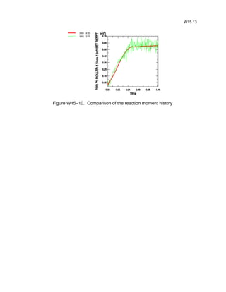
- The workshop simulates quasi-static rolling of a thick plate using ABAQUS/Explicit and ABAQUS/Standard. A half-symmetry plane strain model of a plate and roller is used.
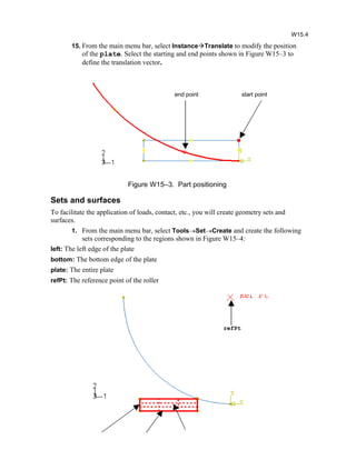
- In ABAQUS/Explicit, mass scaling is used to speed up the single-pass simulation. Adaptive meshing maintains mesh quality during the large deformations. Surface contact is defined between the plate and roller.
- In ABAQUS/Standard, a two-step static analysis is used: contact is first established, then the roller draws the plate in the roll pass. Solution controls account for the discontinuous contact/friction behavior.
TT Smart Stamp è un semplice sistema di anticontraffazione composto da un CODICE QR ed una CORNICE COLORATA. Il CODICE QR fornisce le informazioni per la tracciabilità del prodotto associato. La CORNICE COLORATA fornisce la conferma dell’autenticità del prodotto associato. Questi due elementi combinati generano un MARCHIO NON RIPRODUCIBILE perché legato allo specifico processo di stampa che lo ha generato.
TT Video LIM si basa essenzialmente sull’uso della lavagna interattiva multimediale che, abbinata a sistemi di videoconferenza, consente di realizzare un sistema di e-learning innovativo e di alto livello e di condividere e modificare simultaneamente contenuti tra sedi remote.
This CIM and automation laboratory manual covers the G-Codes and M-codes for CNC Turning and Milling operations. Some concepts of Robot programming are also introduced.
Unit 8 - Information and Communication Technology (Paper I).pdfThiyagu K
This slides describes the basic concepts of ICT, basics of Email, Emerging Technology and Digital Initiatives in Education. This presentations aligns with the UGC Paper I syllabus.
Synthetic Fiber Construction in lab .pptxPavel ( NSTU)
Synthetic fiber production is a fascinating and complex field that blends chemistry, engineering, and environmental science. By understanding these aspects, students can gain a comprehensive view of synthetic fiber production, its impact on society and the environment, and the potential for future innovations. Synthetic fibers play a crucial role in modern society, impacting various aspects of daily life, industry, and the environment. ynthetic fibers are integral to modern life, offering a range of benefits from cost-effectiveness and versatility to innovative applications and performance characteristics. While they pose environmental challenges, ongoing research and development aim to create more sustainable and eco-friendly alternatives. Understanding the importance of synthetic fibers helps in appreciating their role in the economy, industry, and daily life, while also emphasizing the need for sustainable practices and innovation.
Introduction to AI for Nonprofits with Tapp NetworkTechSoup
Dive into the world of AI! Experts Jon Hill and Tareq Monaur will guide you through AI's role in enhancing nonprofit websites and basic marketing strategies, making it easy to understand and apply.
Honest Reviews of Tim Han LMA Course Program.pptxtimhan337
Personal development courses are widely available today, with each one promising life-changing outcomes. Tim Han’s Life Mastery Achievers (LMA) Course has drawn a lot of interest. In addition to offering my frank assessment of Success Insider’s LMA Course, this piece examines the course’s effects via a variety of Tim Han LMA course reviews and Success Insider comments.
Model Attribute Check Company Auto PropertyCeline George
In Odoo, the multi-company feature allows you to manage multiple companies within a single Odoo database instance. Each company can have its own configurations while still sharing common resources such as products, customers, and suppliers.
June 3, 2024 Anti-Semitism Letter Sent to MIT President Kornbluth and MIT Cor...Levi Shapiro
Letter from the Congress of the United States regarding Anti-Semitism sent June 3rd to MIT President Sally Kornbluth, MIT Corp Chair, Mark Gorenberg
Dear Dr. Kornbluth and Mr. Gorenberg,
The US House of Representatives is deeply concerned by ongoing and pervasive acts of antisemitic
harassment and intimidation at the Massachusetts Institute of Technology (MIT). Failing to act decisively to ensure a safe learning environment for all students would be a grave dereliction of your responsibilities as President of MIT and Chair of the MIT Corporation.
This Congress will not stand idly by and allow an environment hostile to Jewish students to persist. The House believes that your institution is in violation of Title VI of the Civil Rights Act, and the inability or
unwillingness to rectify this violation through action requires accountability.
Postsecondary education is a unique opportunity for students to learn and have their ideas and beliefs challenged. However, universities receiving hundreds of millions of federal funds annually have denied
students that opportunity and have been hijacked to become venues for the promotion of terrorism, antisemitic harassment and intimidation, unlawful encampments, and in some cases, assaults and riots.
The House of Representatives will not countenance the use of federal funds to indoctrinate students into hateful, antisemitic, anti-American supporters of terrorism. Investigations into campus antisemitism by the Committee on Education and the Workforce and the Committee on Ways and Means have been expanded into a Congress-wide probe across all relevant jurisdictions to address this national crisis. The undersigned Committees will conduct oversight into the use of federal funds at MIT and its learning environment under authorities granted to each Committee.
• The Committee on Education and the Workforce has been investigating your institution since December 7, 2023. The Committee has broad jurisdiction over postsecondary education, including its compliance with Title VI of the Civil Rights Act, campus safety concerns over disruptions to the learning environment, and the awarding of federal student aid under the Higher Education Act.
• The Committee on Oversight and Accountability is investigating the sources of funding and other support flowing to groups espousing pro-Hamas propaganda and engaged in antisemitic harassment and intimidation of students. The Committee on Oversight and Accountability is the principal oversight committee of the US House of Representatives and has broad authority to investigate “any matter” at “any time” under House Rule X.
• The Committee on Ways and Means has been investigating several universities since November 15, 2023, when the Committee held a hearing entitled From Ivory Towers to Dark Corners: Investigating the Nexus Between Antisemitism, Tax-Exempt Universities, and Terror Financing. The Committee followed the hearing with letters to those institutions on January 10, 202
How to Make a Field invisible in Odoo 17Celine George
It is possible to hide or invisible some fields in odoo. Commonly using “invisible” attribute in the field definition to invisible the fields. This slide will show how to make a field invisible in odoo 17.
Embracing GenAI - A Strategic ImperativePeter Windle
Artificial Intelligence (AI) technologies such as Generative AI, Image Generators and Large Language Models have had a dramatic impact on teaching, learning and assessment over the past 18 months. The most immediate threat AI posed was to Academic Integrity with Higher Education Institutes (HEIs) focusing their efforts on combating the use of GenAI in assessment. Guidelines were developed for staff and students, policies put in place too. Innovative educators have forged paths in the use of Generative AI for teaching, learning and assessments leading to pockets of transformation springing up across HEIs, often with little or no top-down guidance, support or direction.
This Gasta posits a strategic approach to integrating AI into HEIs to prepare staff, students and the curriculum for an evolving world and workplace. We will highlight the advantages of working with these technologies beyond the realm of teaching, learning and assessment by considering prompt engineering skills, industry impact, curriculum changes, and the need for staff upskilling. In contrast, not engaging strategically with Generative AI poses risks, including falling behind peers, missed opportunities and failing to ensure our graduates remain employable. The rapid evolution of AI technologies necessitates a proactive and strategic approach if we are to remain relevant.
A Strategic Approach: GenAI in EducationPeter Windle
Artificial Intelligence (AI) technologies such as Generative AI, Image Generators and Large Language Models have had a dramatic impact on teaching, learning and assessment over the past 18 months. The most immediate threat AI posed was to Academic Integrity with Higher Education Institutes (HEIs) focusing their efforts on combating the use of GenAI in assessment. Guidelines were developed for staff and students, policies put in place too. Innovative educators have forged paths in the use of Generative AI for teaching, learning and assessments leading to pockets of transformation springing up across HEIs, often with little or no top-down guidance, support or direction.
This Gasta posits a strategic approach to integrating AI into HEIs to prepare staff, students and the curriculum for an evolving world and workplace. We will highlight the advantages of working with these technologies beyond the realm of teaching, learning and assessment by considering prompt engineering skills, industry impact, curriculum changes, and the need for staff upskilling. In contrast, not engaging strategically with Generative AI poses risks, including falling behind peers, missed opportunities and failing to ensure our graduates remain employable. The rapid evolution of AI technologies necessitates a proactive and strategic approach if we are to remain relevant.
1.4 modern child centered education - mahatma gandhi-2.pptx
Workshop15 rolling-plate
1. Workshop 15
Single Pass Rolling of a Thick Plate
Introduction
Rolling is a basic manufacturing technique used to transform preformed shapes into a
form suitable for further processing. The rolling process is essentially quasi-static because
rolling is normally performed at relatively low speeds (typically 1 m/s) and, therefore,
inertia effects are not significant.
Representative rolling geometries generally require three-dimensional modeling, resulting
in very large models, and include both nonlinear material behavior and nonlinear
boundary effects (contact and friction). For this reason the explicit dynamics approach is
often less expensive computationally and more reliable than an implicit quasi-static
solution if mass scaling is used.
This workshop involves simulating quasi-static rolling of a plate using ABAQUS/Explicit.
The rolling process reduces the thickness of the plate by 45% in a single rolling pass.
Mass scaling will be used to reduce the solution time for analysis. For the purpose of
comparison, the simulation will also be performed using the implicit solver available with
ABAQUS/Standard.
This workshop is based in part on ABAQUS Example Problem 1.3.6.
Geometry and model
A half-symmetry plane strain model will be used with the plate having a length of 0.92 m
and a half-thickness of 0.02 m. A 90 segment of the roller is constructed as an analytical
rigid surface.
1. Start a new session of ABAQUS/CAE from the workshops/rolling
directory.
2. Switch to the Part module.
A default model name is assigned by ABAQUS/CAE (Model-1). However, since the
explicit dynamics model will later form the basis of the implicit analysis model, you
should rename the current model to give it a more descriptive name.
3. From the main menu bar, select ModelRenameModel-1. Rename the
model Explicit.
4. From the main menu bar, select PartCreate. Name the part plate, choose
the modeling space as 2D, and set the approximate size of the sketch area to
0.25. Review the other defaults, and click Continue.
5. Using the Create Lines: Rectangle tool, sketch a rectangle 0.092 m long
and 0.020 m high, as shown in Figure W15–1.
2. Figure W15–1. Plate geometry
6. From the main menu bar, select PartCreate. Name the part roller, choose
the part type as Analytical rigid, the modeling space as 2D, the base feature as
Planar wire, and set the approximate size of the sketch area to 1.0. Review
the other defaults, and click Continue.
7. Using the Create Isolated Point, create two points with the coordinates
(-0.170, 0.170) and (0, 0.170).
8. Using the Create Arc tool, sketch a 90 arc centered at the point (0, 0.170), as
shown in Figure W15–2.
Figure W15–2. Roller geometry
9. From the main menu bar, select ToolsReference Point and choose the
center of the arc to create a reference point for the part.
Materials and section
The steel plate is assumed to be elastic-plastic. Although rate-dependent plastic behavior
is usually considered in rolling simulations, it is not considered here.
W15.2
3. 1. Switch to the Property module.
10. From the main menu bar, select MaterialCreate. Create a material named
Steel with the following properties:
· Modulus of elasticity: 1.5E11 Pa
· Poisson's ratio: 0.3
· Density: 7850 kg/m3
· The initial yield stress is 168.72 MPa rising to 448.45 MPa at 100% strain.
The plasticity data are summarized in Table W15–1:
Yield stress (Pa) Plastic strain
1.6872 E8 0.0
2.1933 E8 0.1
2.7202 E8 0.2
3.0853 E8 0.3
3.3737 E8 0.4
3.6158 E8 0.5
3.8265 E8 0.6
4.0142 E8 0.7
4.1842 E8 0.8
4.3401 E8 0.9
4.4845 E8 1.0
Table W15–1. Yield stress-plastic strain data
11. From the main menu bar, select SectionCreate and create a homogeneous
solid section named plateSection with a default thickness of 1.0.
12. From the main menu bar, select AssignSection and assign the section to the
part named plate.
Assembly
You must now instance the parts and position the plate relative to the roller.
1. Switch to the Assembly module.
13. From the main menu bar, select InstanceCreate, select both parts, and click
OK.
To position the plate relative to the roller, it is necessary to identify the location on the
roller where contact will first occur between the parts. Then datum geometry can be used
to facilitate the positioning. In this problem the top-right corner of the plate will first make
contact with the roller at a point that is located approximately 20% of the distance along
the edge of the roller (relative to the bottom vertex of the roller).
14. From the main menu bar, select ToolsDatumPoint. Choose the Use
parameter method, select the roller edge, and specify a normalized edge
parameter of 0.2.
W15.3
4. 15. From the main menu bar, select InstanceTranslate to modify the position
of the plate. Select the starting and end points shown in Figure W15–3 to
define the translation vector.
Figure W15–3. Part positioning
Sets and surfaces
To facilitate the application of loads, contact, etc., you will create geometry sets and
surfaces.
1. From the main menu bar, select ToolsSetCreate and create the following
sets corresponding to the regions shown in Figure W15–4:
left: The left edge of the plate
bottom: The bottom edge of the plate
plate: The entire plate
refPt: The reference point of the roller
W15.4
end point start point
refPt
5. Figure W15–4. Geometry sets
16. From the main menu bar, select ToolsSurfaceCreate and create the
following surfaces corresponding to the regions shown in Figure W15–5:
roller: Side of the roller facing the plate
topPlate: Top and right edges of the plate
Figure W15–5. Surfaces
Analysis step and output requests
The rolling simulation will be performed using a single explicit dynamics analysis step.
1. Switch to the Step module.
17. From the main menu bar, select StepCreate to create a Dynamic, Explicit
step named Single Pass Rolling with a time period of 0.1 seconds. Accept
all defaults for the time incrementation and other parameters.
Because rate effects are usually considered in rolling problems, the only method available
to speed up the simulation effectively is mass scaling.
18. Open the Mass Scaling tabbed page of the Edit Step dialog box. In this page,
select Use scaling definitions below then click Create. Choose the
Application Region as Set; and from the pull down menu, select plate.
Enter a scale by factor value of 1600, and click OK.
19. Accept the default field output requests. From the main menu bar, select
OutputHistory Output RequestsCreate and request stored history
output to the output database at 100 equally spaced time intervals during the
analysis for reaction moment RM3 at the roller reference point. Use the set
named refPoint.
W15.5
left bottom plate
topPlateroller
6. Very large deformations are anticipated in this analysis. Use the adaptive meshing
capability available in ABAQUS/Explicit to reduce the amount of mesh distortion and
maintain a high quality mesh throughout the analysis.
20. From the main menu bar, select OtherAdaptive Mesh DomainManager.
a. In the Adaptive Mesh Domain Manager, click Edit.
a. In the Edit Adaptive Mesh Domain dialog box, toggle on Use the
adaptive mesh domain below. Select plate as the region. Specify a
frequency of 10 and 3 mesh sweeps per increment.
b. Toggle on Adaptive mesh controls, and click Create in the right side of
the dialog box. Define adaptive mesh controls using all supplied default
parameters.
Contact
Surface-to-surface contact will be defined between the top surface of the plate and the
outer surface of the roller. Coulomb friction with a coefficient of 0.4 will be used.
1. Switch to the Interaction module.
21. From the main menu bar, select InteractionPropertyCreateContact
and click Continue.
22. Select MechanicalTangential Behavior, and choose the Penalty friction
formulation.
23. Enter a friction coefficient of 0.4. Click OK.
24. From the main menu bar, select InteractionCreate.
25. In the Create Interaction dialog box, select Single Pass Rolling as the step
and select Surface-to-surface contact (Explicit) as the interaction type. Click
Continue. When prompted for the surfaces involved in the contact interaction,
click Surfaces in the prompt area to open the Region Selection dialog box.
Select roller as the master surface and topPlate as the slave surface.
Boundary conditions
The roller spins about the global Z-axis with an angular velocity of 6.2832 radians/sec.
The plate will be given an initial velocity of 1.01587m/sec in the global X-direction, which
is equal to the X-direction velocity component of the roller at the point where contact first
occurs. This minimizes the initial transient disturbance since the initial acceleration in the
X-direction at the contact point is zero.
1. Switch to the Load module.
26. From the main menu bar, select BCManager to open the Boundary
Condition Manager. Create the boundary conditions listed in Table W15–2:
a. Click Create in the Boundary Condition Manager.
c. In the Create Boundary Condition dialog box, select
Displacement/Rotation as the type and click Continue.
BC name Step Region Boundary condition
W15.6
7. bottom Initial bottom U2=0
fixRoll Initial refPt U1=U2=0
rotateRoll Single pass rolling refPt VR3=6.2832
Table W15–2. Boundary conditions
Initial conditions
As mentioned earlier, the plate is given an initial velocity of 1.01587 m/sec in the global
X-direction.
1. From the main menu bar, select FieldCreate.
27. In the Create Field dialog box, name the field initVel, set the step to
Initial, accept the default category, and click Continue.
28. In the prompt area, click Sets, select plate, and click Continue.
29. In the Edit Field box, enter a value of 1.01587 m/sec for the velocity
component V1.
Mesh
The plate will be meshed with 150 plane strain CPE4R elements.
1. Switch to the Mesh module.
30. From the main menu bar, select MeshElement Type and select the plate by
clicking on it. Examine the various options available in the Element type
dialog box, change the element library to Explicit and the element family to
Plane Strain, and accept the default element type CPE4R.
31. From the main menu bar, select SeedInstance, select the plate, and specify
a seed size of 0.002.
32. From the main menu bar, select MeshInstance. Select the plate as the
instance to be meshed, and click Done in the prompt area. The mesh is shown
in Figure W15–6.
Figure W15–6. Plate mesh
W15.7
8. Analysis
1. Switch to the Job Module.
33. Select JobCreate, create a job named roll-xpl, and click Continue.
Accept the default job parameters, and click OK.
34. From the main menu bar, select FileSave As and save the model database as
roll.cae.
35. From the main menu bar, select JobManager to open the Job Manager.
Click Submit to submit the job for analysis.
36. Monitor the progress of the job by clicking Monitor in the Job Manager.
Visualization
1. Once the analysis completes successfully, click Results in the Job Manager.
37. Plot the undeformed and the deformed model shapes.
38. From the main menu bar, select ViewODB Display Options and under the
Sweep and Extrude tab, set the Depth to 0.01. Turn on shaded render style,
and rotate the model.
39. Plot the contours for MISES stress and plastic strain PEEQ. The contours for
Mises stress are show in Figure W15–7.
Figure W15–7. Mises stress contours
40. From the main menu bar, select AnimateTime History to animate the
history of the Mises stress distribution and the resulting deformation.
41. From the main menu bar, select ResultHistory output to create X–Y plots
for the model kinetic energy (ALLKE), external work (ALLWK), internal
energy (ALLIE), and total energy (ETOTAL). In the History Output dialog
box, click Plot to display the curves and click Dismiss to close the box. The
plot is shown in Figure W15–8.
W15.8
9. Figure W15–8. Model energies
42. Plot the history of the reaction moment RM3, and save the curve as RM3 XPL.
Implicit analysis model
Now perform the simulation using ABAQUS/Standard. From the main menu bar, select
ModelCopy, and copy the model named explicit to a new model named
standard. Make the following changes to this model:
1. Switch to the Step module, and delete the step named Single Pass Rolling.
Note that this deletes all previously defined step-dependent objects such as
loads, contact interactions, etc.
For the implicit analysis, the static analysis procedure will be used. Note, however, that
the simple analysis technique used earlier (whereby the initial plate velocity was
prescribed and a single analysis step was used) will not yield the desired results in
ABAQUS/Standard. The reason is that, in a static step material, inertia is neglected. Thus,
two steps are needed to perform the simulation. In the first step firm contact must be
established between the plate and the roller. This then allows the roller to draw the plate in
the second step, where the roll pass event will be simulated.
43. Create a Static, General step named Establish Contact with the
following parameters:
· Total time period = 0.001 sec
· Maximum number of increments = 100
· Initial time increment size = 0.0001 sec
· Minimum increment size = 1E-8 sec
· Maximum increment size = 0.001 sec
· NLGEOM toggled on
W15.9
10. 44. Create a second Static, General named Roll Pass with the following
parameters:
· Total time period = 0.099 sec
· Maximum number of increments = 500
· Initial time increment size = 0.0001 sec
· Minimum increment size = 9.9E-7 sec
· Maximum increment size = 0.099 sec
45. Create a history output request for reaction moment RM3 for the set refPt.
46. From the main menu bar, select OutputRestart Requests and specify a
restart frequency of 250 for each step.
For problems dominated by highly discontinuous nonlinearities (such as contact and
friction), nondefault analysis controls may aid the convergence behavior. In this problem
allow extra equilibrium iterations for the resolution of these discontinuities, as described
below.
47. From the main menu bar, select OtherSolution ControlsEdit Roll
Pass to edit the solution controls for this step.
48. In the solution controls editor, select Specify. In the Time Incrementation
tabbed page of this dialog box, select Discontinuous analysis. Click OK to
close the dialog box.
49. Switch to the Interaction module.
a. From the main menu bar, select InteractionCreate.
d. In the Create Interaction dialog box, select the step Establish Contact,
accept the default Surface-to-surface contact (Standard) type, and click
Continue.
e. In the prompt area, click Surfaces; use roller as the master surface, and
topPlate as the slave surface.
50. Switch to the Load module.
a. From the main menu bar, select BCCreate.
f. In the Create Boundary Condition dialog box, select Velocity/Angular
velocity as the type and click Continue.
g. Create the following velocity conditions for the sets as shown in
Table W15–3.
BC name Step Region Boundary condition
feed piece Establish Contact left V1=1.01587
roller Establish Contact refPt VR3=6.2832
Table W15–3. Boundary conditions
h. From the main menu bar, select BCManager, select the feed piece
boundary condition in the Roll Pass step, and Deactivate it.
51. Switch to the Mesh module.
W15.10
11. a. From the main menu bar, select MeshElement Type.
i. Select the plate; and, in the Element type dialog box, change the element
library to Standard and click OK.
52. Switch to the Job module.
a. Select JobCreate, and create a job named roll-std.
b. Save the model database.
j. Open the Job Manager, and submit the job roll-std for analysis.
k. Monitor the progress of the job by clicking Monitor in the Job Manager.
W15.11
12. Visualization
1. Once the analysis completes successfully, click Results in the Job Manager.
53. Plot the undeformed and the deformed model shapes.
54. Plot the contours for MISES stress and plastic strain PEEQ.
55. Resize the viewport by clicking on its lower right corner and dragging it so that
it covers the top half of the canvas area. Create a second viewport by selecting
CanvasCreate Viewport from the main menu bar, and draw a rectangle by
dragging the mouse across the lower half of the canvas area.
56. Switch to the output database file roll-xpl.odb, and plot the contours for
PEEQ. The contours for PEEQ for both analyses are shown in Figure W15–9.
Figure W15–9. PEEQ for the implicit and explicit solutions
57. Save the time history for the reaction moment RM3 as RM3 STD. Plot both
curves as shown in Figure W15–10.
W15.12
implicit solution
explicit solution