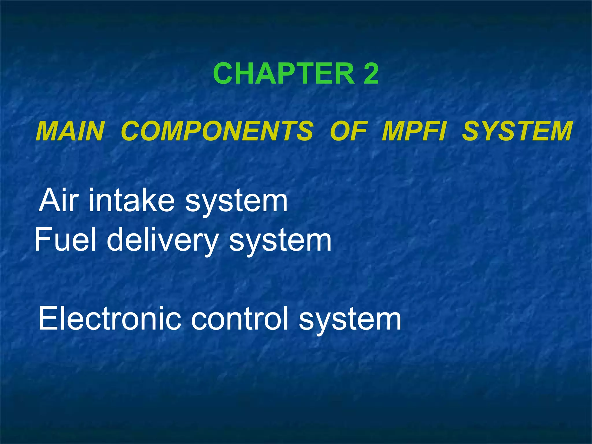
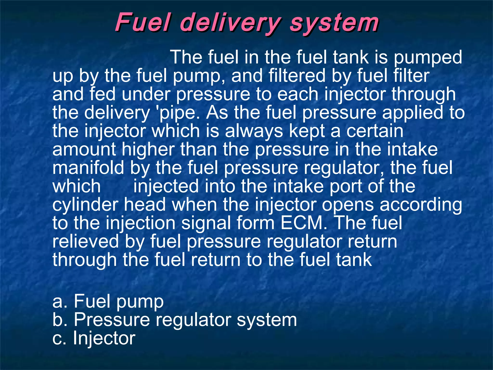
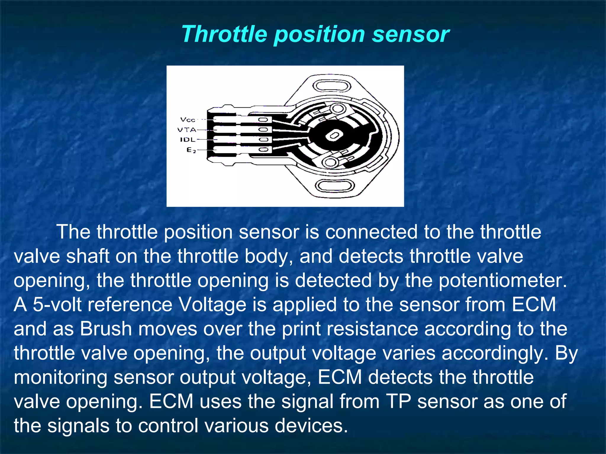
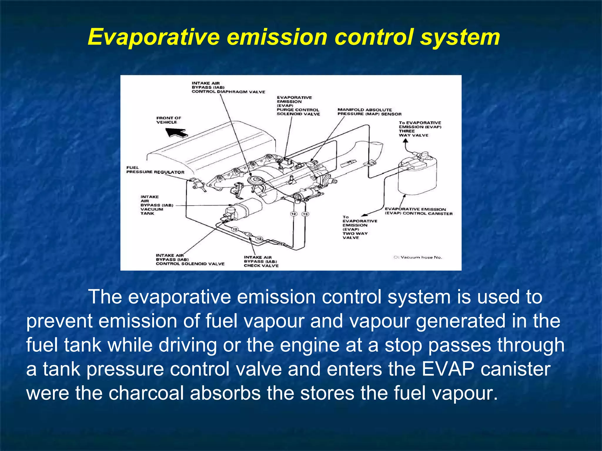
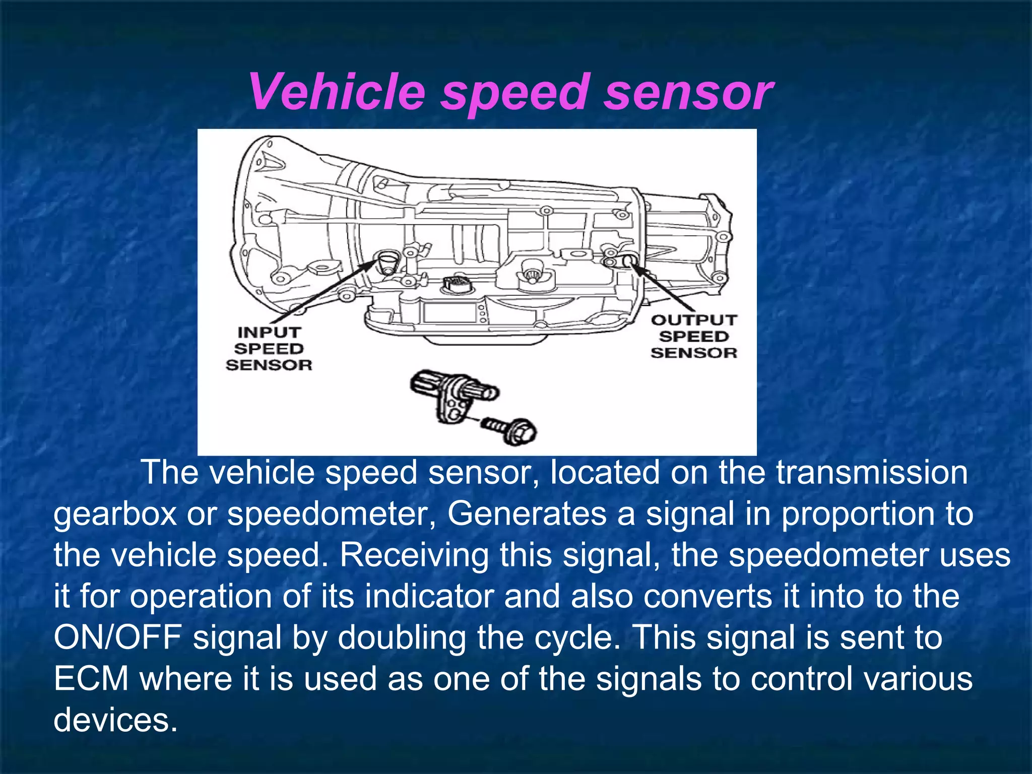
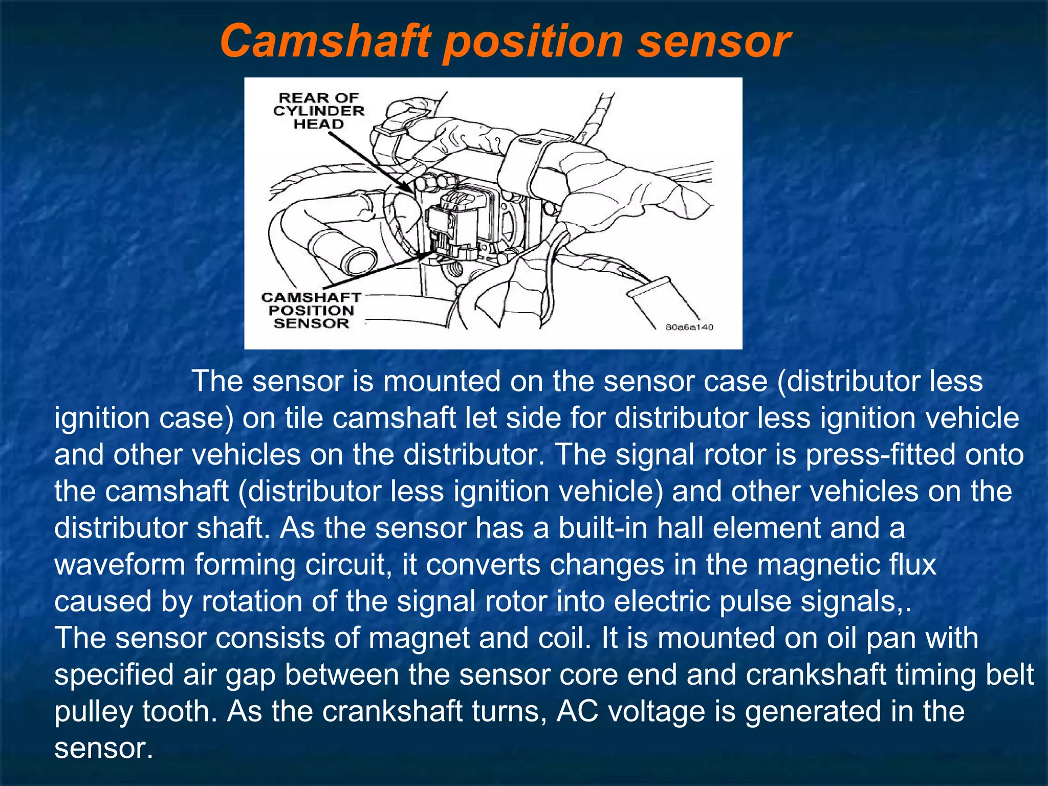
AA
SEMINAR REPORT ONSEMINAR REPORT ON
MULTI POINT FUEL INJECTIONMULTI POINT FUEL INJECTION
SUBMITTED BY,SUBMITTED BY,
Mr. SHIrISH S. MOGALADEMr. SHIrISH S. MOGALADE
IN THE SUBJECT OFIN THE SUBJECT OF
PROFESSIONAL PRACTICES VPROFESSIONAL PRACTICES V
LATTHE POLYTECHNIC,SANGLILATTHE POLYTECHNIC,SANGLI ..
INDEX
Cha
pter
no.
Name of chapter Page no.
1 Introduction 1
2 Main components
of MPFI
2
3 Working of MPFI 8
4 Sensors used in
MPFI
13
5 Advantages 17
Conclusion 18
References 19
CHAPTER 1
INTRODUCTION
Petrol vehicles uses device called carburetor for supplying the air
fuel mixture in correct ratio to cylinders in all rpm ranges. Due to
construction of the carburetor is relatively simple, it has been used almost
exclusively on gasoline engines in the past. However in response to recent
demands for cleaner exhaust emission, more economical fuel consumption,
improved drivability, etc., so the carburetor must be equipped with various
complicated devices, making it more complex system.
So In place of the carburetor, therefore, the MPFI (multi point fuel
injection) system is used, assuring proper air fuel ratio to the engine by
electrically injecting fuel in accordance with various driving conditions.
MPFIMPFI ::
MPFI is a system which uses a smallMPFI is a system which uses a small
computer to control the car engine. A carcomputer to control the car engine. A car
engine has three or more cylinders orengine has three or more cylinders or
burning zones and one fuel injector isburning zones and one fuel injector is
installed near each cylinder, hence theinstalled near each cylinder, hence the
system is called Multi point fuel injectionsystem is called Multi point fuel injection
system.system.
CHAPTER 2
MAIN COMPONENTS OF MPFI SYSTEM
Air intake system
Fuel delivery system
Electronic control system
Air intake systemAir intake system
The air (corresponding to the throttle valveThe air (corresponding to the throttle valve
opening) is filtered by the air cleaner, passesopening) is filtered by the air cleaner, passes
through the throttle body, and is distributed bythrough the throttle body, and is distributed by
the intake manifold and finally drawn intothe intake manifold and finally drawn into
each combustion chamber.When the lACeach combustion chamber.When the lAC
valve is opened according to the signal fromvalve is opened according to the signal from
ECM, the air bypasses through throttle valveECM, the air bypasses through throttle valve
is finally drawn into the intake manifoldis finally drawn into the intake manifold
a. Throttle bodya. Throttle body
b. Idle air control valveb. Idle air control valve
Fuel delivery systemFuel delivery system
The fuel in the fuel tank is pumped
up by the fuel pump, and filtered by fuel filter
and fed under pressure to each injector through
the delivery 'pipe. As the fuel pressure applied to
the injector which is always kept a certain
amount higher than the pressure in the intake
manifold by the fuel pressure regulator, the fuel
which injected into the intake port of the
cylinder head when the injector opens according
to the injection signal form ECM. The fuel
relieved by fuel pressure regulator return
through the fuel return to the fuel tank
a. Fuel pump
b. Pressure regulator system
c. Injector
Electronic control systemElectronic control system
The electronic control system consist of various sensors
which detect the state of engine and driving conditions, ECM
which controls various devices according to the signals from the
sensors and Various controlled devices.
Various Electronic control
systems
Fuel injection control system
Idle speed control system
Fuel pump control system
Ignition control system
Radiator fan control system
CHAPTER 5
SENSORS USED IN MPFI.
Manifold absolute pressure sensor
This sensor senses pressure change in the intake
manifold and converts it into voltage Change. It consists of a
semi-conductor type pressure converting element, which converts
a pressure change into an electrical change and, an electronic
circuit which amplifies and corrects the electric change. The ECM
sends a 5-volt reference voltage to the pressure sensor. As the
manifold pressure changes, the electrical resistance of the sensor
also changes By monitoring the sensor output voltage ,ECM
knows the manifold pressure, ECM uses the voltage signal from
the pressure sensor as one of the signals to control fuel injector.
Throttle position sensor
The throttle position sensor is connected to the throttle
valve shaft on the throttle body, and detects throttle valve
opening, the throttle opening is detected by the potentiometer.
A 5-volt reference Voltage is applied to the sensor from ECM
and as Brush moves over the print resistance according to the
throttle valve opening, the output voltage varies accordingly. By
monitoring sensor output voltage, ECM detects the throttle
valve opening. ECM uses the signal from TP sensor as one of
the signals to control various devices.
Evaporative emission control system
The evaporative emission control system is used to
prevent emission of fuel vapour and vapour generated in the
fuel tank while driving or the engine at a stop passes through
a tank pressure control valve and enters the EVAP canister
were the charcoal absorbs the stores the fuel vapour.
Located on the air cleaner outlet hose, this
sensor constantly measures the temperature of the
air entering and converts a change in the air
temperature Into that resistance through its
thermistor. That is, as is temperature lower
resistance increases and as it rises, resistance
decreases. As air density of the intake air varies
with Variation in temperature, ECM, by monitoring
the resistance, adjusts the amount of fuel injection
according to the air temperature
Intake air temperature sensors
Engine coolant temperature sensor
Incorporated with coolant temperature. Gauge
and installed to the thermostat case, this sensor
measures the temperature of the engine coolant and
converts its change into that in resistance through
the thermistor like the air temperature sensor, by
monitoring the resistance of coolant temperature
sensor, ECM detects the engine coolant temperature
and that affects most systems under the control of
ECM.
The oxygen sensor is installed on the exhaust manifold to detect
the concentration of oxygen in the exhaust gases. in order of engines
equipped with the three- way catalytic converter to achieve their best
exhaust emission purification performance, it is necessary for the air-
fuel ratio to be kept within a narrow range near the theoretical air-fuel
ratio The oxygen sensor senses whether the air-fuel ratio is richer on
leaner than the theoretical air-fuel ratio, The oxygen sensor is located
in the exhaust manifold and consists of an element made of zirconium
dioxide (zrO2, a kind of ceramic material) ¬This element is coated on
both inside and outside with a thin layer of platinum. Atmospheric air is
introduced into the inside of the sensor, and outside of the sensor is
exposed to the exhaust gases. If the Oxygen concentration on the
inside surface of the zirconium element differs greatly from that on the
outside surface at high temperatures, the zirconium element generate
a voltage when the air-fuel mixture is lean there is lot of oxygen in the
exhaust gas, so there is a little difference between oxygen
concentration inside and outside the sensor element.
Oxygen sensors
Vehicle speed sensor
The vehicle speed sensor, located on the transmission
gearbox or speedometer, Generates a signal in proportion to
the vehicle speed. Receiving this signal, the speedometer uses
it for operation of its indicator and also converts it into to the
ON/OFF signal by doubling the cycle. This signal is sent to
ECM where it is used as one of the signals to control various
devices.
Camshaft position sensor
The sensor is mounted on the sensor case (distributor less
ignition case) on tile camshaft let side for distributor less ignition vehicle
and other vehicles on the distributor. The signal rotor is press-fitted onto
the camshaft (distributor less ignition vehicle) and other vehicles on the
distributor shaft. As the sensor has a built-in hall element and a
waveform forming circuit, it converts changes in the magnetic flux
caused by rotation of the signal rotor into electric pulse signals,.
The sensor consists of magnet and coil. It is mounted on oil pan with
specified air gap between the sensor core end and crankshaft timing belt
pulley tooth. As the crankshaft turns, AC voltage is generated in the
sensor.
CHAPTER 6
ADVANTAGES OF MPFI
1) More uniform A/F mixture will be supplied to each cylinder;
hence the difference in power developed in each cylinder is
minimum. Vibration from the engine equipped with this system is
less; due to this the life of engine components is improved.
(2) No need to crank the engine twice or thrice in case of cold
starting as happens in the carburetor system
(3) Immediate response, in case of sudden acceleration /
deceleration.
(4) Since the engine is controlled by ECM (Engine Control
Module), more accurate amount of A/F mixture will be supplied and
as a result complete combustion will take place. This leads to
effective utilization of fuel supplied and hence low emission level.
(5) The mileage of the vehicle will be improved.
CONCLUSION
Almost all vehicles in India are changing to the
MPFI because of law emissions, improved mileage and
drivability since the engine is controlled by micro
computer more accurate amount of a/f mixture will be
supplied and as a result complete combustion will take
place. This leads to effective utilization of fuel supplied
and hence low emission level. It reduces wastage of fuel
by the use of sensors and other control systems
REFERENCES
Automotive technology –Jack
erjavec
Automobile engineering – Anil
chhakra
Automobile engineering-
V.Ganesh
http://www.howstuffworks
.com
http://www.indiacar.com
THANK YOU…THANK YOU…

Mpfi ppt

  • 1.
    AA SEMINAR REPORT ONSEMINARREPORT ON MULTI POINT FUEL INJECTIONMULTI POINT FUEL INJECTION
  • 2.
    SUBMITTED BY,SUBMITTED BY, Mr.SHIrISH S. MOGALADEMr. SHIrISH S. MOGALADE
  • 3.
    IN THE SUBJECTOFIN THE SUBJECT OF PROFESSIONAL PRACTICES VPROFESSIONAL PRACTICES V LATTHE POLYTECHNIC,SANGLILATTHE POLYTECHNIC,SANGLI ..
  • 4.
    INDEX Cha pter no. Name of chapterPage no. 1 Introduction 1 2 Main components of MPFI 2 3 Working of MPFI 8 4 Sensors used in MPFI 13 5 Advantages 17 Conclusion 18 References 19
  • 5.
    CHAPTER 1 INTRODUCTION Petrol vehiclesuses device called carburetor for supplying the air fuel mixture in correct ratio to cylinders in all rpm ranges. Due to construction of the carburetor is relatively simple, it has been used almost exclusively on gasoline engines in the past. However in response to recent demands for cleaner exhaust emission, more economical fuel consumption, improved drivability, etc., so the carburetor must be equipped with various complicated devices, making it more complex system. So In place of the carburetor, therefore, the MPFI (multi point fuel injection) system is used, assuring proper air fuel ratio to the engine by electrically injecting fuel in accordance with various driving conditions.
  • 6.
    MPFIMPFI :: MPFI isa system which uses a smallMPFI is a system which uses a small computer to control the car engine. A carcomputer to control the car engine. A car engine has three or more cylinders orengine has three or more cylinders or burning zones and one fuel injector isburning zones and one fuel injector is installed near each cylinder, hence theinstalled near each cylinder, hence the system is called Multi point fuel injectionsystem is called Multi point fuel injection system.system.
  • 7.
    CHAPTER 2 MAIN COMPONENTSOF MPFI SYSTEM Air intake system Fuel delivery system Electronic control system
  • 8.
    Air intake systemAirintake system The air (corresponding to the throttle valveThe air (corresponding to the throttle valve opening) is filtered by the air cleaner, passesopening) is filtered by the air cleaner, passes through the throttle body, and is distributed bythrough the throttle body, and is distributed by the intake manifold and finally drawn intothe intake manifold and finally drawn into each combustion chamber.When the lACeach combustion chamber.When the lAC valve is opened according to the signal fromvalve is opened according to the signal from ECM, the air bypasses through throttle valveECM, the air bypasses through throttle valve is finally drawn into the intake manifoldis finally drawn into the intake manifold a. Throttle bodya. Throttle body b. Idle air control valveb. Idle air control valve
  • 9.
    Fuel delivery systemFueldelivery system The fuel in the fuel tank is pumped up by the fuel pump, and filtered by fuel filter and fed under pressure to each injector through the delivery 'pipe. As the fuel pressure applied to the injector which is always kept a certain amount higher than the pressure in the intake manifold by the fuel pressure regulator, the fuel which injected into the intake port of the cylinder head when the injector opens according to the injection signal form ECM. The fuel relieved by fuel pressure regulator return through the fuel return to the fuel tank a. Fuel pump b. Pressure regulator system c. Injector
  • 10.
    Electronic control systemElectroniccontrol system The electronic control system consist of various sensors which detect the state of engine and driving conditions, ECM which controls various devices according to the signals from the sensors and Various controlled devices.
  • 11.
    Various Electronic control systems Fuelinjection control system Idle speed control system Fuel pump control system Ignition control system Radiator fan control system
  • 12.
    CHAPTER 5 SENSORS USEDIN MPFI. Manifold absolute pressure sensor This sensor senses pressure change in the intake manifold and converts it into voltage Change. It consists of a semi-conductor type pressure converting element, which converts a pressure change into an electrical change and, an electronic circuit which amplifies and corrects the electric change. The ECM sends a 5-volt reference voltage to the pressure sensor. As the manifold pressure changes, the electrical resistance of the sensor also changes By monitoring the sensor output voltage ,ECM knows the manifold pressure, ECM uses the voltage signal from the pressure sensor as one of the signals to control fuel injector.
  • 13.
    Throttle position sensor Thethrottle position sensor is connected to the throttle valve shaft on the throttle body, and detects throttle valve opening, the throttle opening is detected by the potentiometer. A 5-volt reference Voltage is applied to the sensor from ECM and as Brush moves over the print resistance according to the throttle valve opening, the output voltage varies accordingly. By monitoring sensor output voltage, ECM detects the throttle valve opening. ECM uses the signal from TP sensor as one of the signals to control various devices.
  • 14.
    Evaporative emission controlsystem The evaporative emission control system is used to prevent emission of fuel vapour and vapour generated in the fuel tank while driving or the engine at a stop passes through a tank pressure control valve and enters the EVAP canister were the charcoal absorbs the stores the fuel vapour.
  • 15.
    Located on theair cleaner outlet hose, this sensor constantly measures the temperature of the air entering and converts a change in the air temperature Into that resistance through its thermistor. That is, as is temperature lower resistance increases and as it rises, resistance decreases. As air density of the intake air varies with Variation in temperature, ECM, by monitoring the resistance, adjusts the amount of fuel injection according to the air temperature Intake air temperature sensors
  • 16.
    Engine coolant temperaturesensor Incorporated with coolant temperature. Gauge and installed to the thermostat case, this sensor measures the temperature of the engine coolant and converts its change into that in resistance through the thermistor like the air temperature sensor, by monitoring the resistance of coolant temperature sensor, ECM detects the engine coolant temperature and that affects most systems under the control of ECM.
  • 17.
    The oxygen sensoris installed on the exhaust manifold to detect the concentration of oxygen in the exhaust gases. in order of engines equipped with the three- way catalytic converter to achieve their best exhaust emission purification performance, it is necessary for the air- fuel ratio to be kept within a narrow range near the theoretical air-fuel ratio The oxygen sensor senses whether the air-fuel ratio is richer on leaner than the theoretical air-fuel ratio, The oxygen sensor is located in the exhaust manifold and consists of an element made of zirconium dioxide (zrO2, a kind of ceramic material) ¬This element is coated on both inside and outside with a thin layer of platinum. Atmospheric air is introduced into the inside of the sensor, and outside of the sensor is exposed to the exhaust gases. If the Oxygen concentration on the inside surface of the zirconium element differs greatly from that on the outside surface at high temperatures, the zirconium element generate a voltage when the air-fuel mixture is lean there is lot of oxygen in the exhaust gas, so there is a little difference between oxygen concentration inside and outside the sensor element. Oxygen sensors
  • 18.
    Vehicle speed sensor Thevehicle speed sensor, located on the transmission gearbox or speedometer, Generates a signal in proportion to the vehicle speed. Receiving this signal, the speedometer uses it for operation of its indicator and also converts it into to the ON/OFF signal by doubling the cycle. This signal is sent to ECM where it is used as one of the signals to control various devices.
  • 19.
    Camshaft position sensor Thesensor is mounted on the sensor case (distributor less ignition case) on tile camshaft let side for distributor less ignition vehicle and other vehicles on the distributor. The signal rotor is press-fitted onto the camshaft (distributor less ignition vehicle) and other vehicles on the distributor shaft. As the sensor has a built-in hall element and a waveform forming circuit, it converts changes in the magnetic flux caused by rotation of the signal rotor into electric pulse signals,. The sensor consists of magnet and coil. It is mounted on oil pan with specified air gap between the sensor core end and crankshaft timing belt pulley tooth. As the crankshaft turns, AC voltage is generated in the sensor.
  • 20.
    CHAPTER 6 ADVANTAGES OFMPFI 1) More uniform A/F mixture will be supplied to each cylinder; hence the difference in power developed in each cylinder is minimum. Vibration from the engine equipped with this system is less; due to this the life of engine components is improved. (2) No need to crank the engine twice or thrice in case of cold starting as happens in the carburetor system (3) Immediate response, in case of sudden acceleration / deceleration. (4) Since the engine is controlled by ECM (Engine Control Module), more accurate amount of A/F mixture will be supplied and as a result complete combustion will take place. This leads to effective utilization of fuel supplied and hence low emission level. (5) The mileage of the vehicle will be improved.
  • 21.
    CONCLUSION Almost all vehiclesin India are changing to the MPFI because of law emissions, improved mileage and drivability since the engine is controlled by micro computer more accurate amount of a/f mixture will be supplied and as a result complete combustion will take place. This leads to effective utilization of fuel supplied and hence low emission level. It reduces wastage of fuel by the use of sensors and other control systems
  • 22.
    REFERENCES Automotive technology –Jack erjavec Automobileengineering – Anil chhakra Automobile engineering- V.Ganesh http://www.howstuffworks .com http://www.indiacar.com
  • 23.