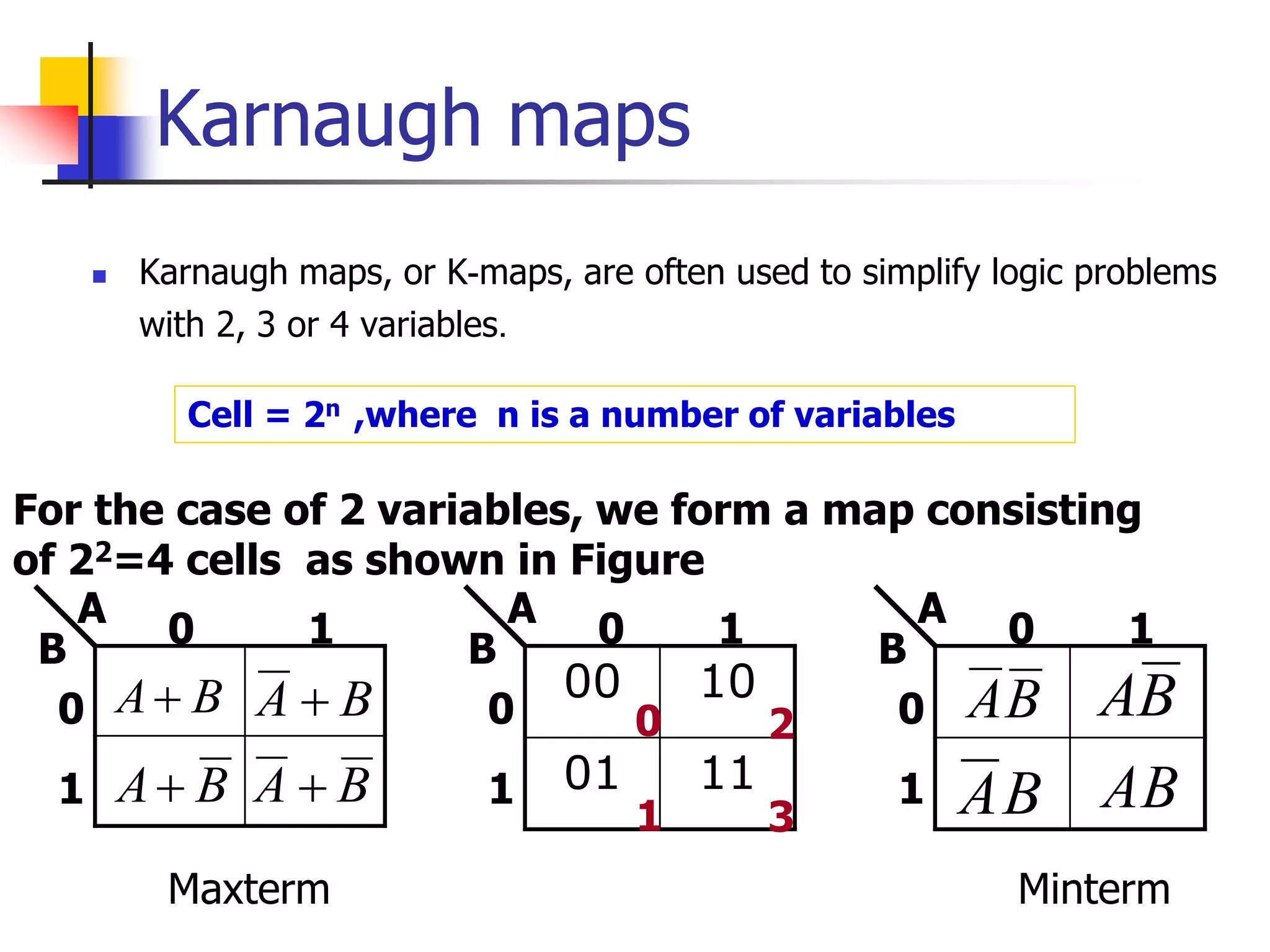
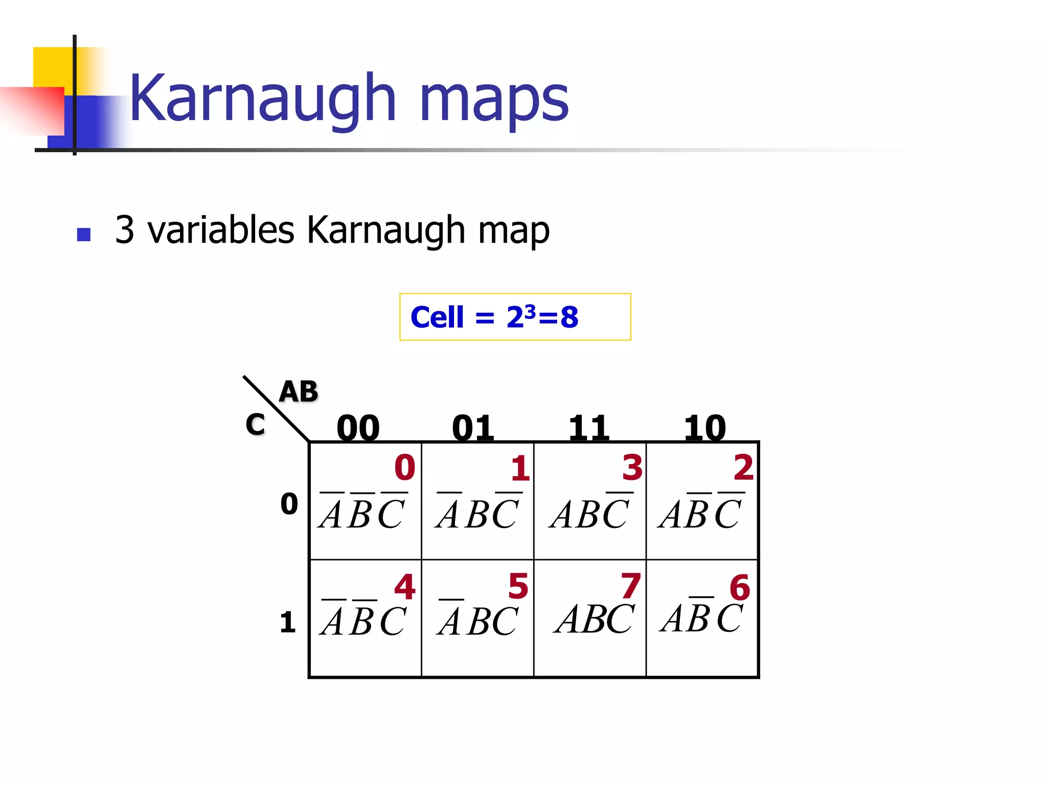
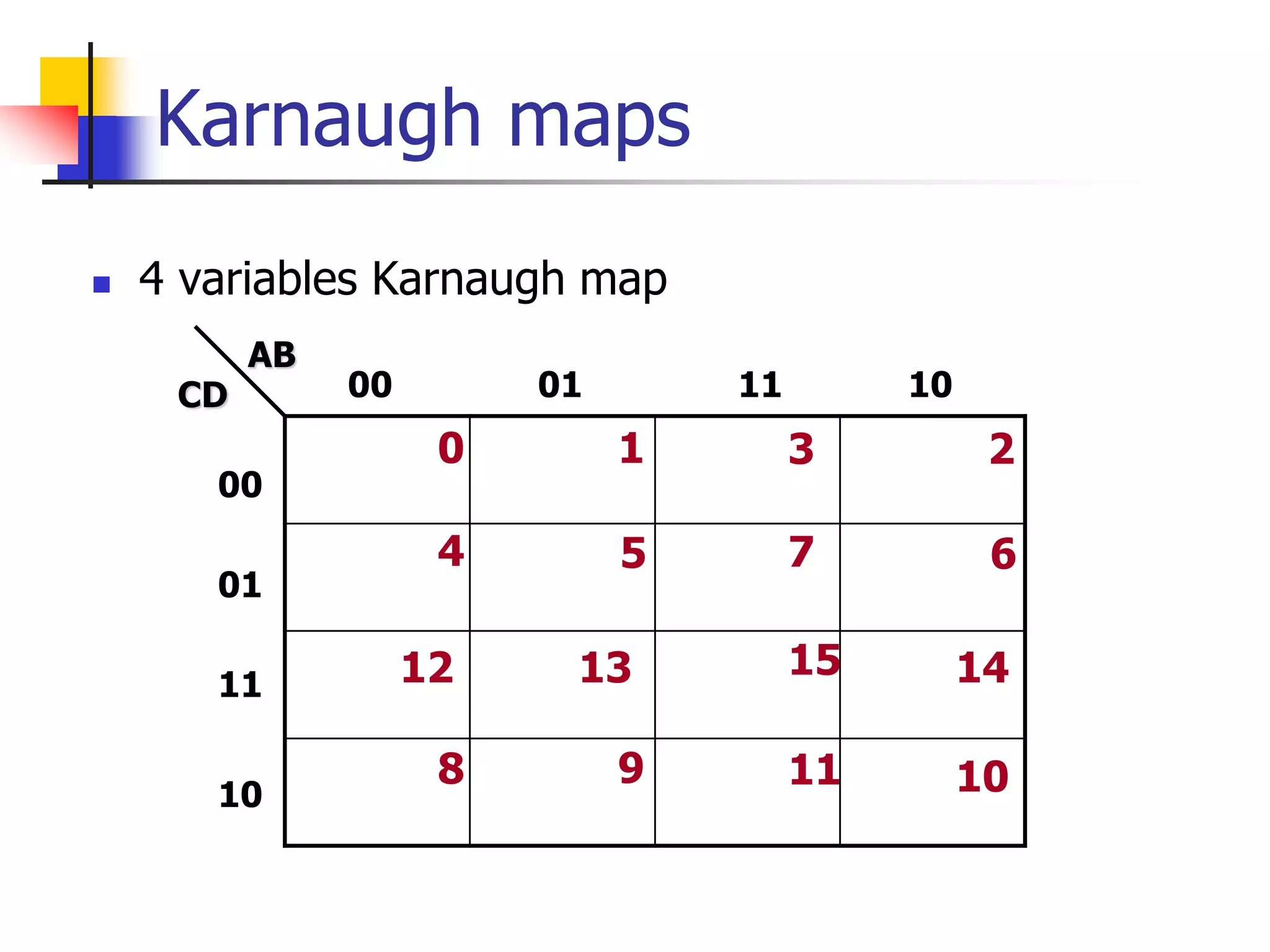
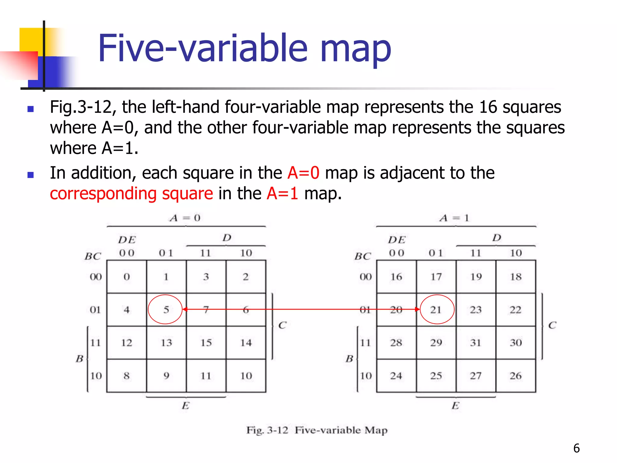
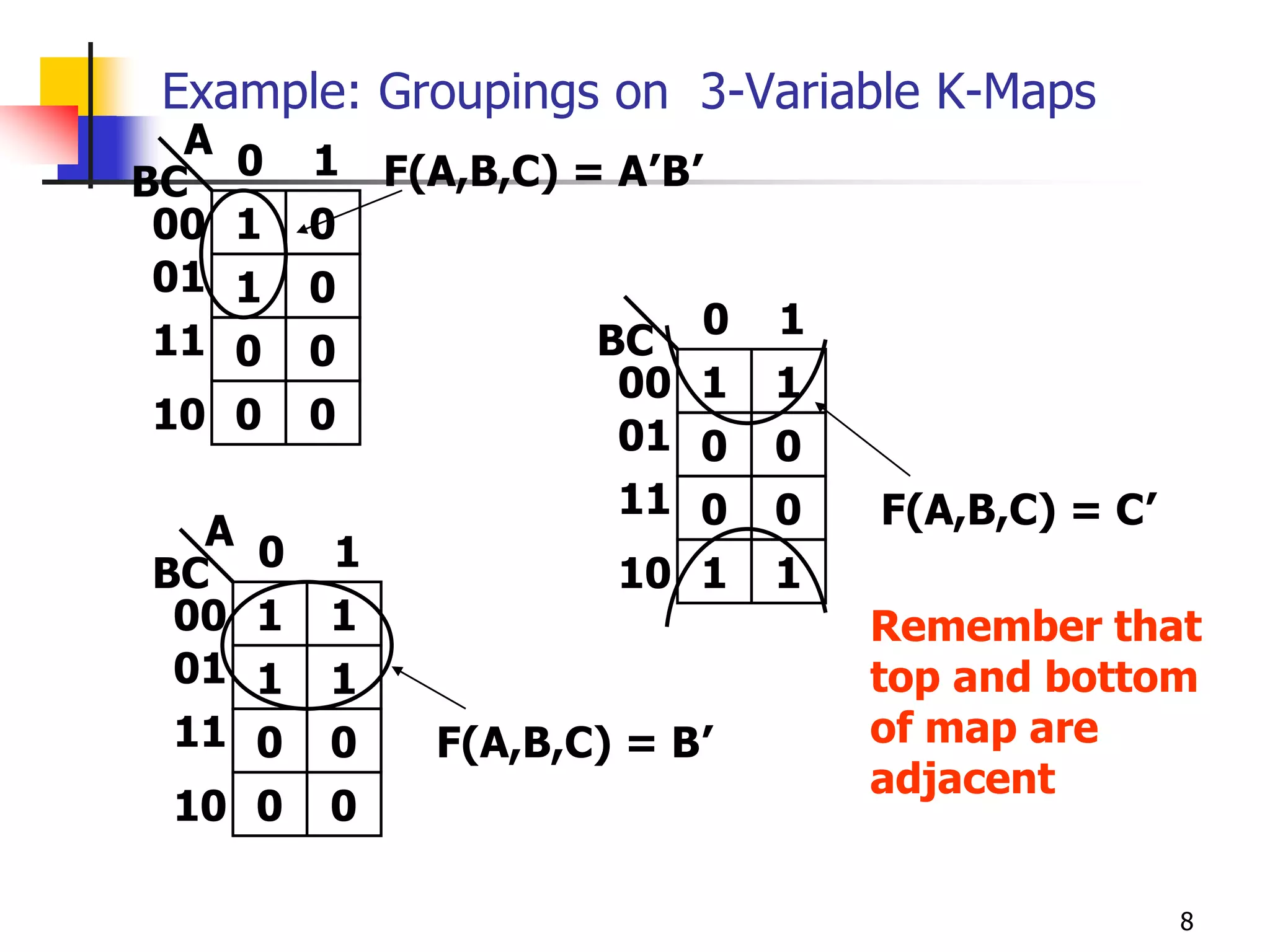
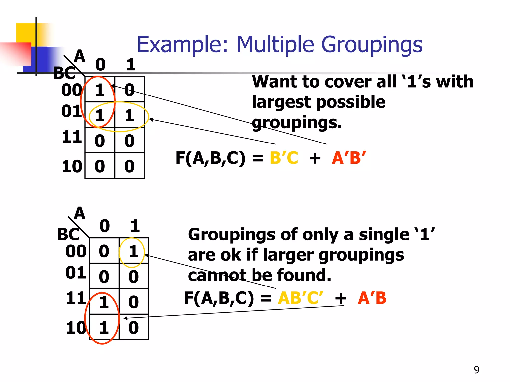
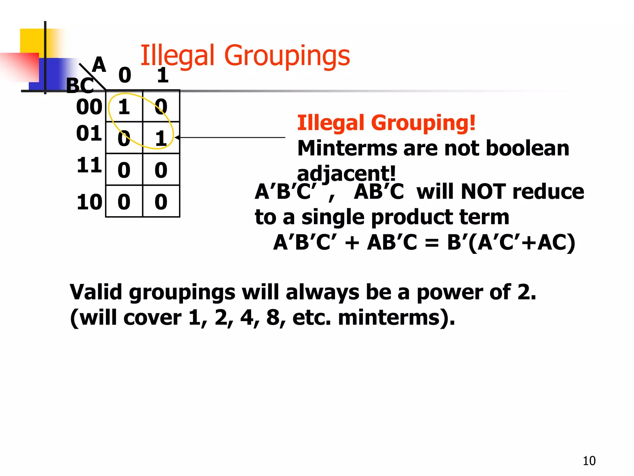
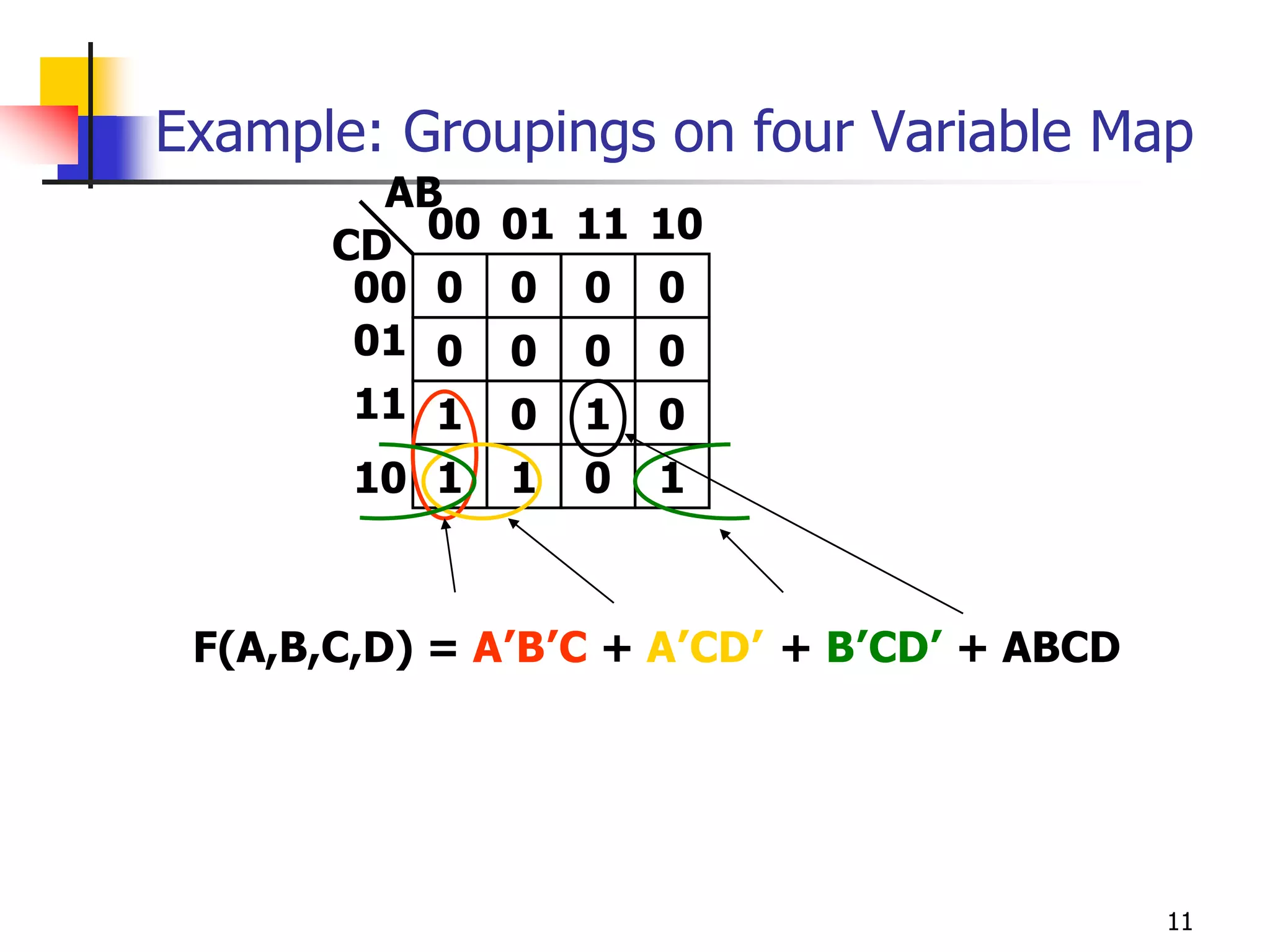
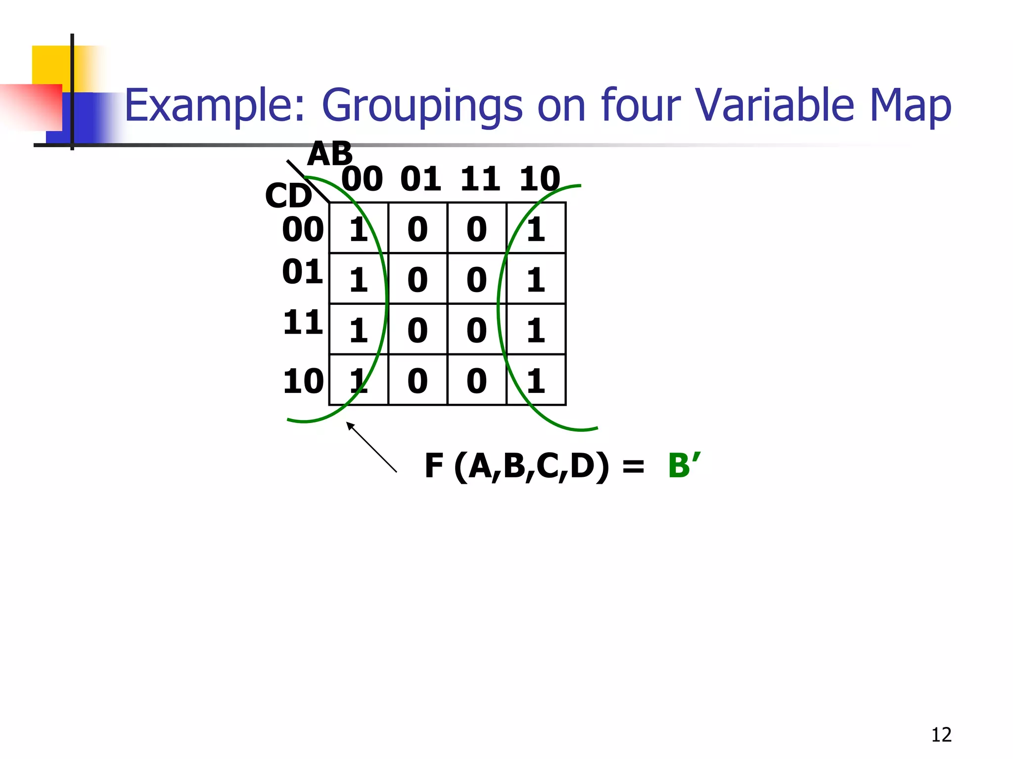
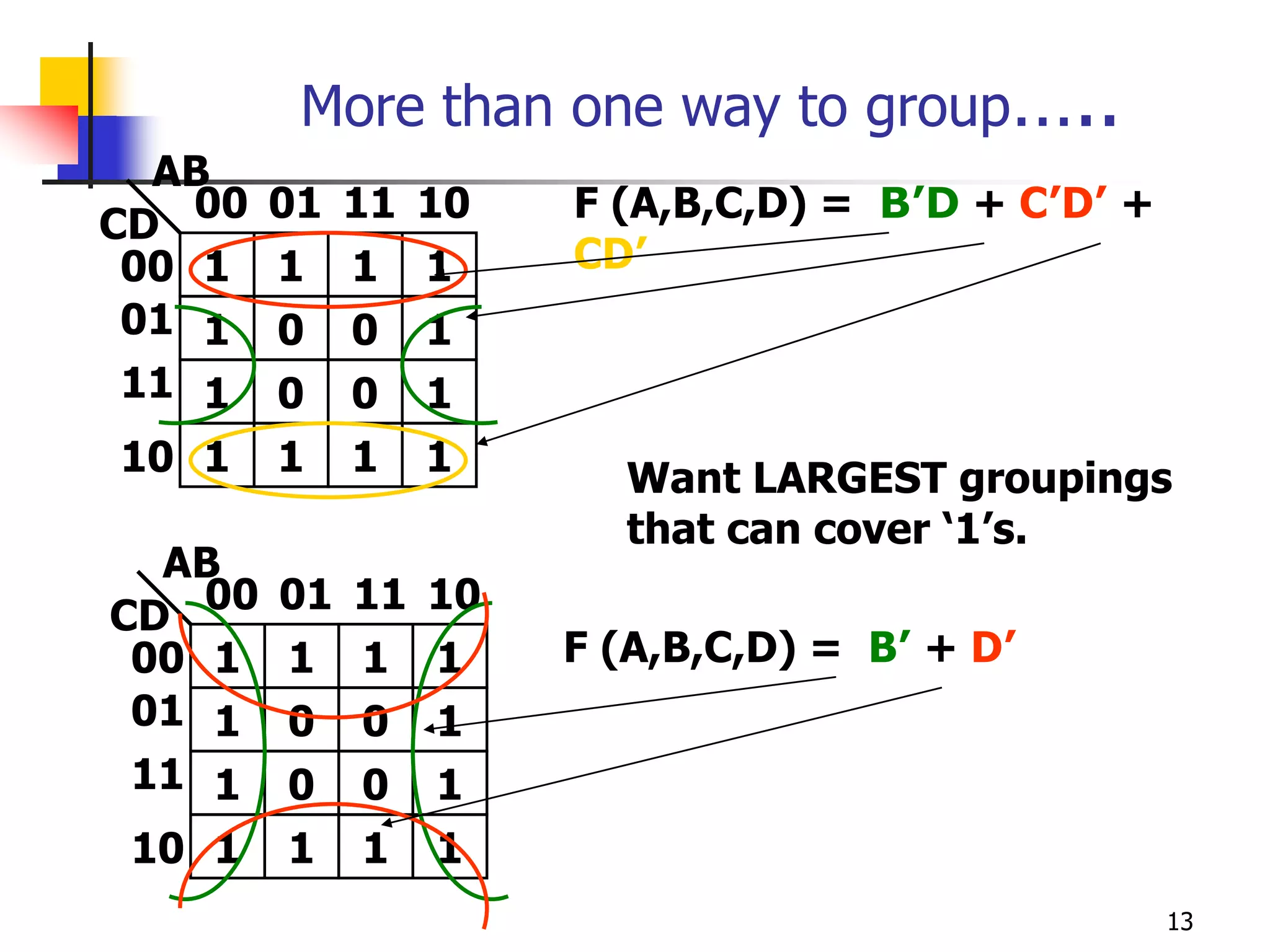
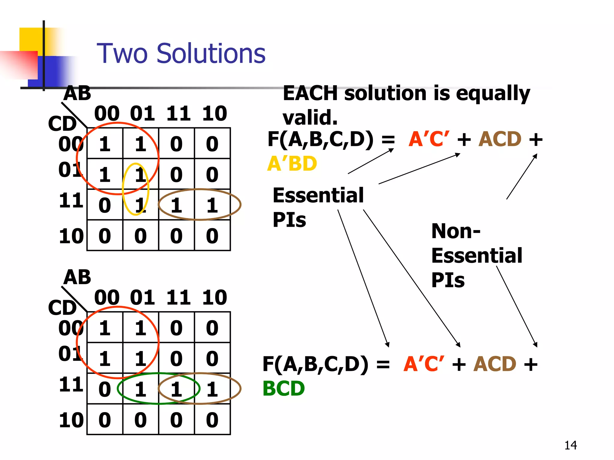
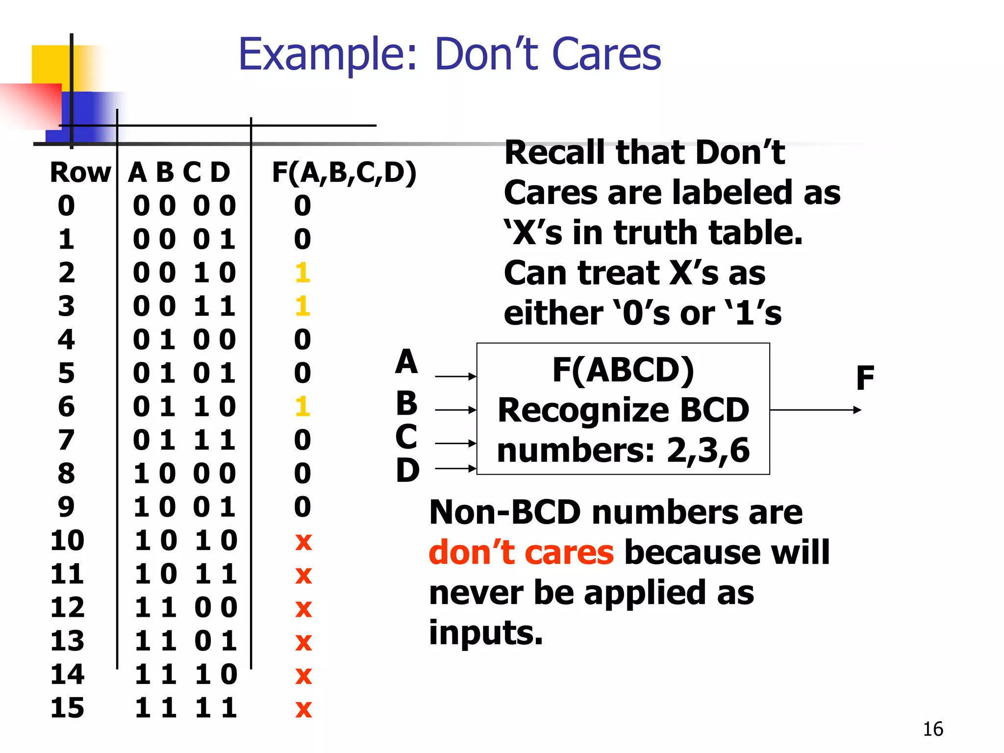
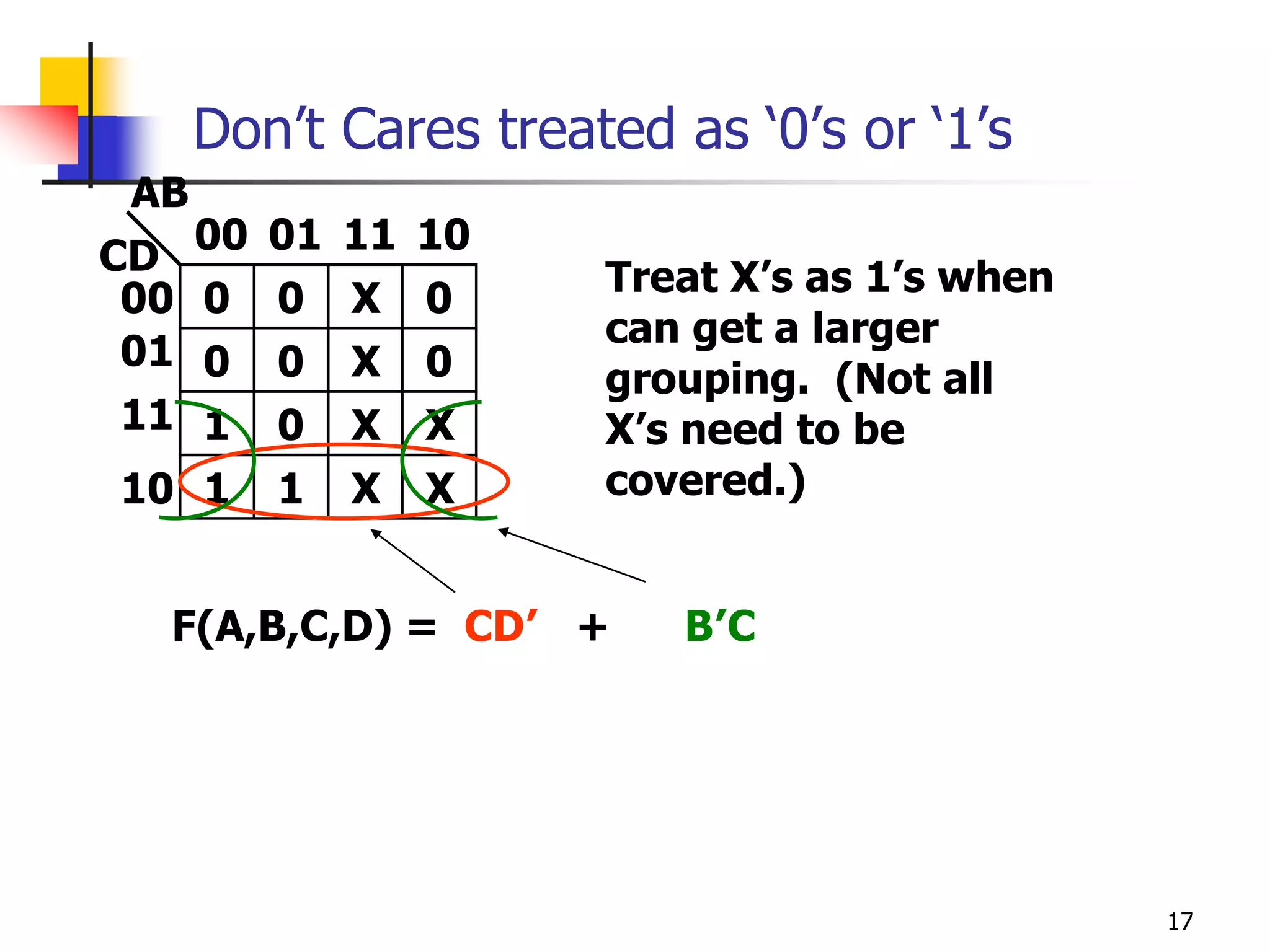
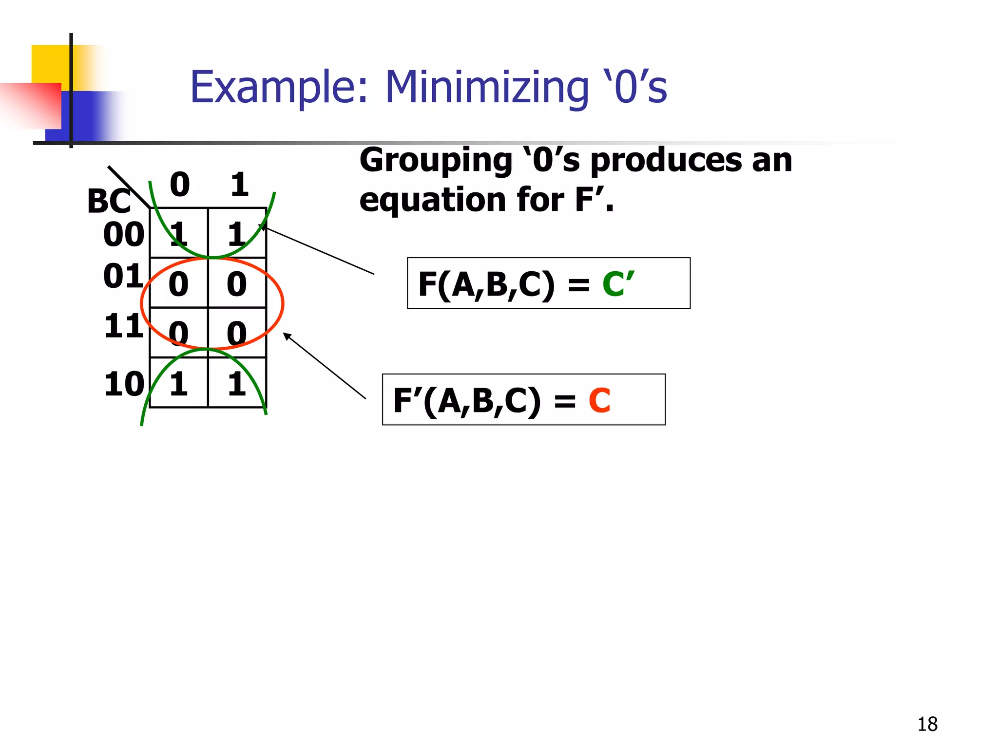
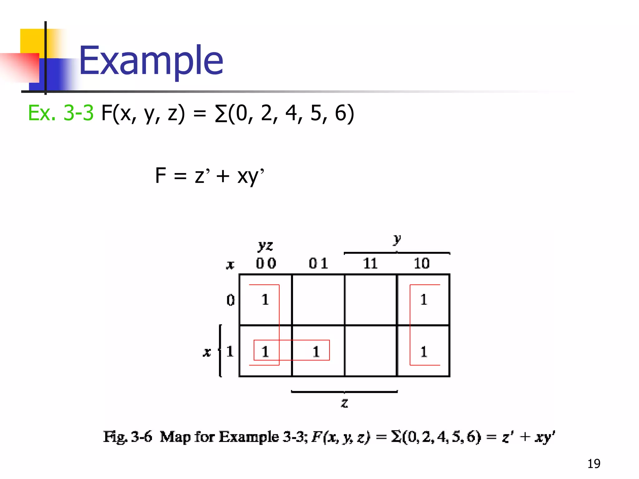
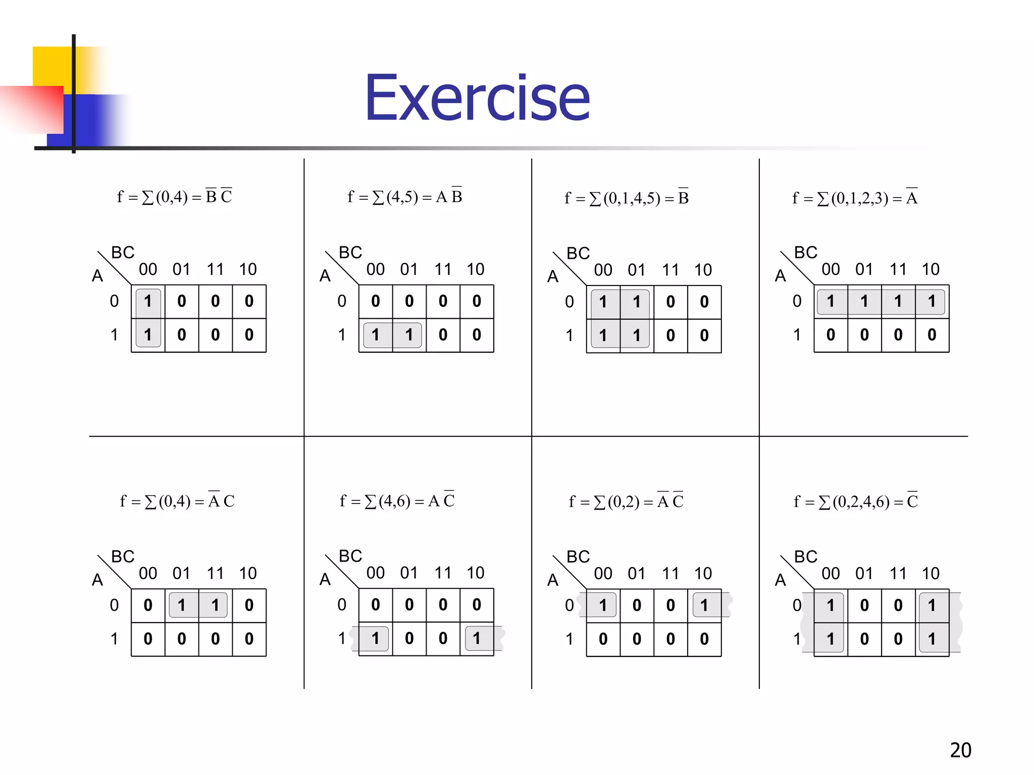
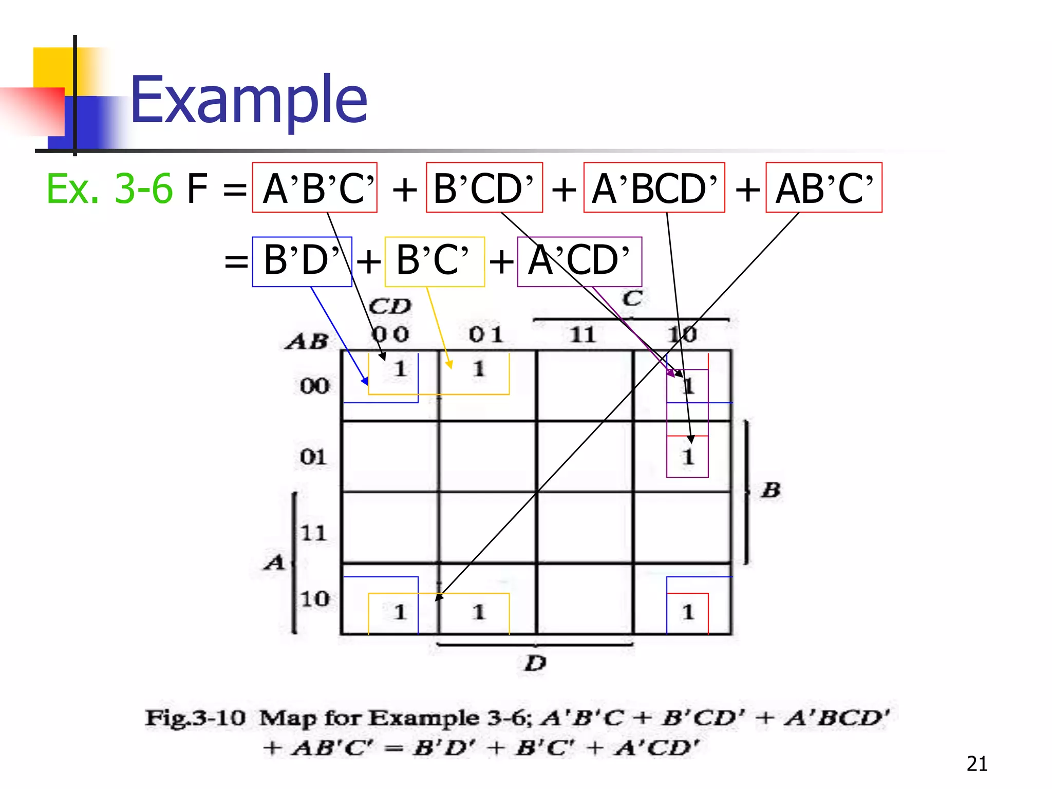
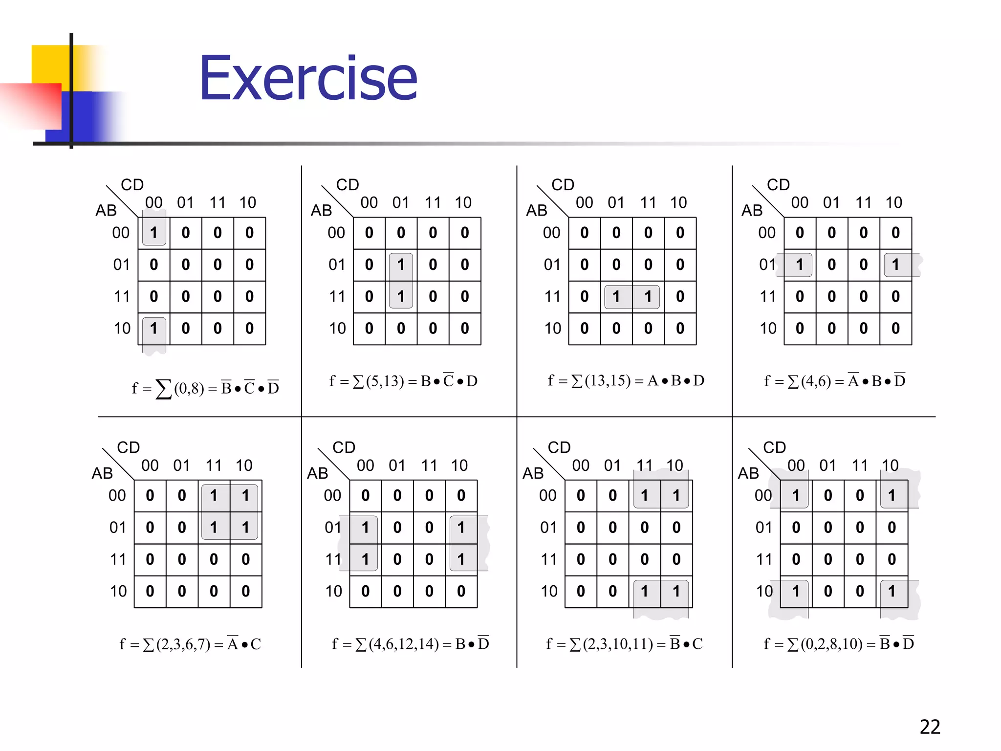
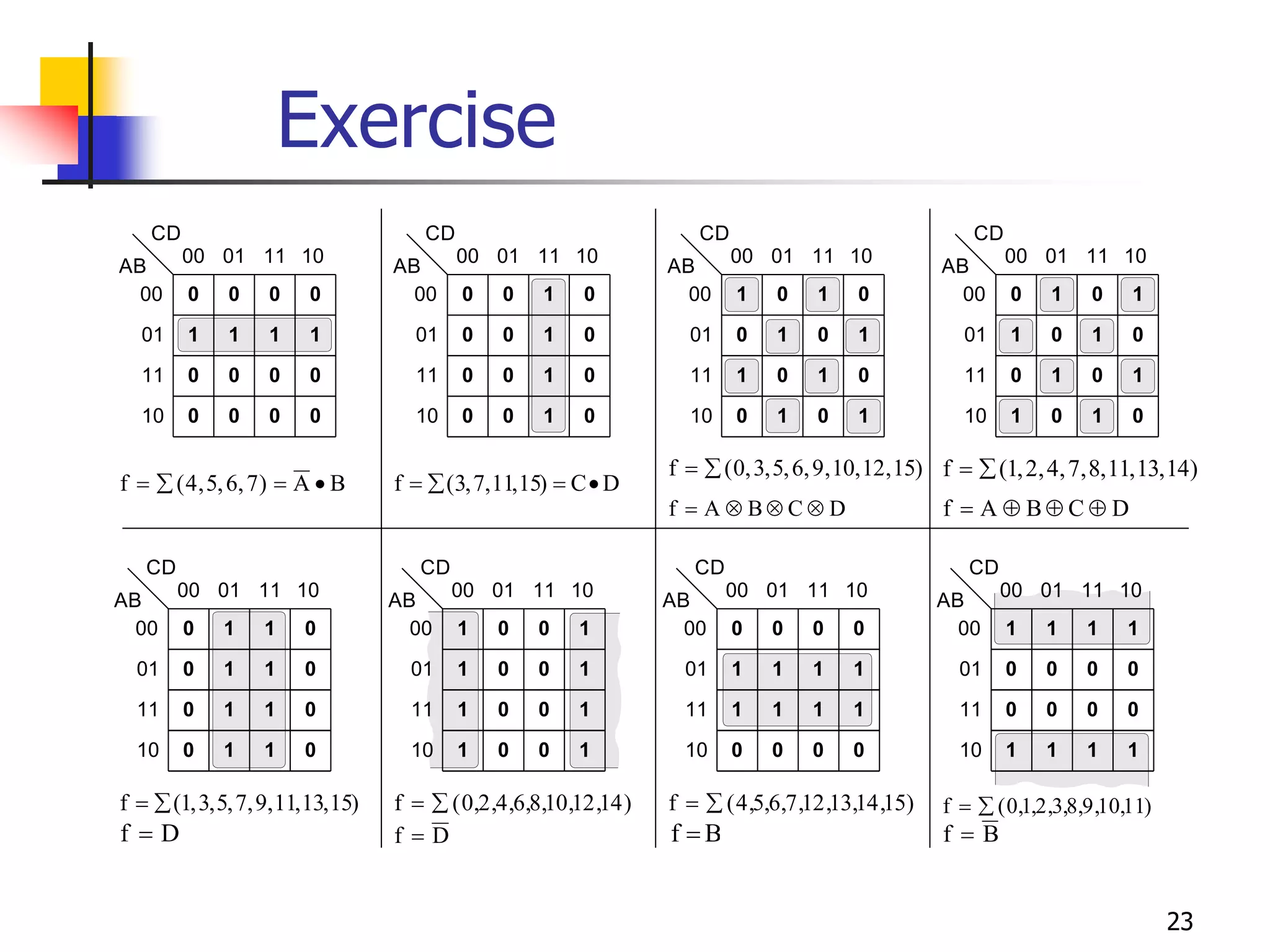
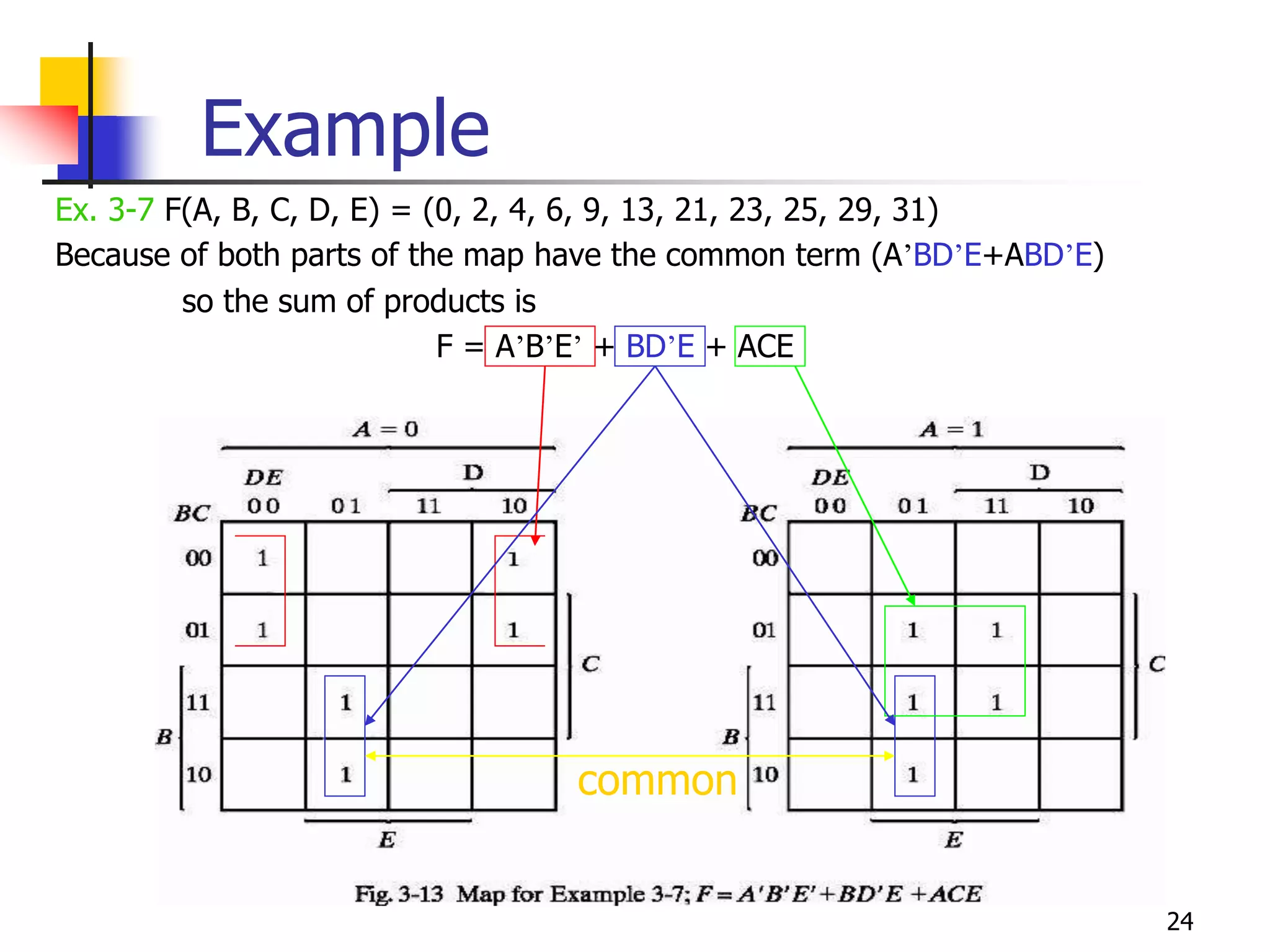
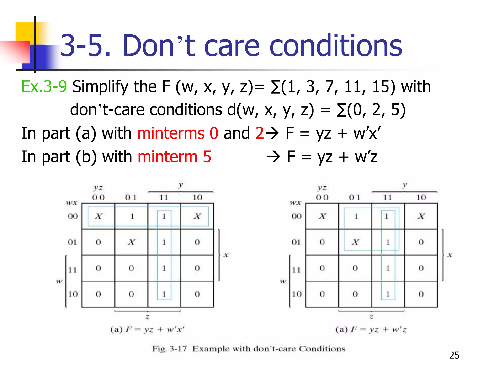
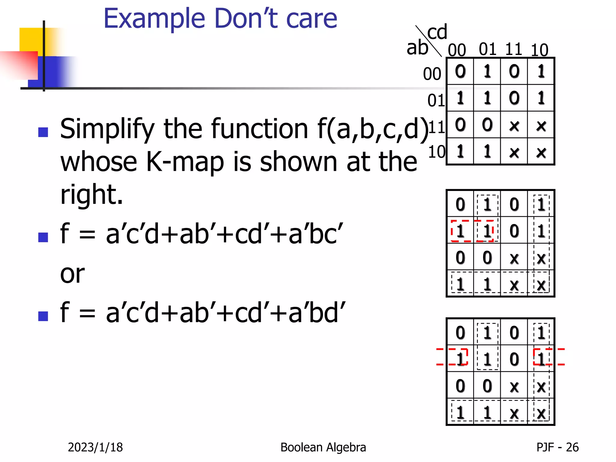
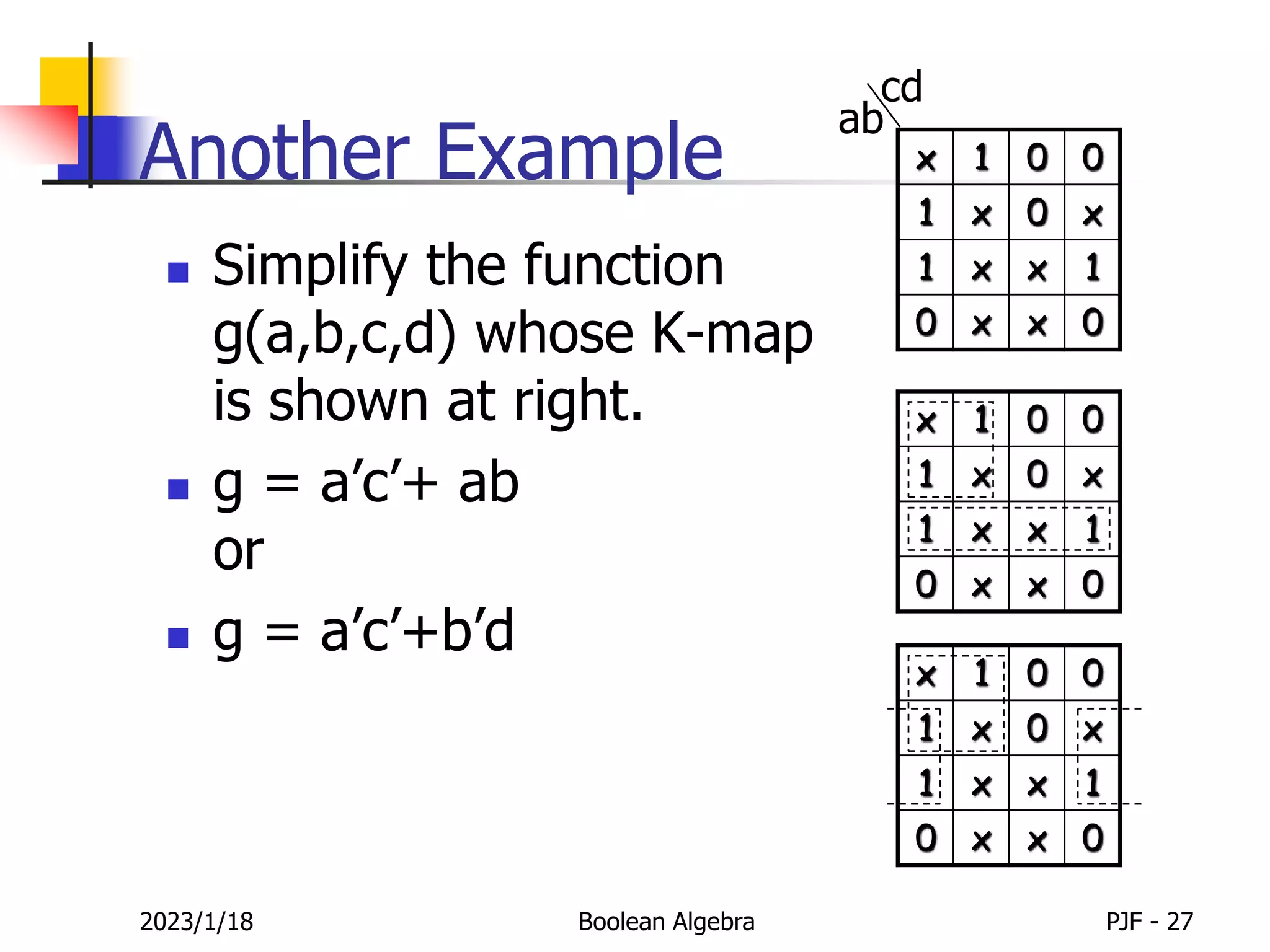
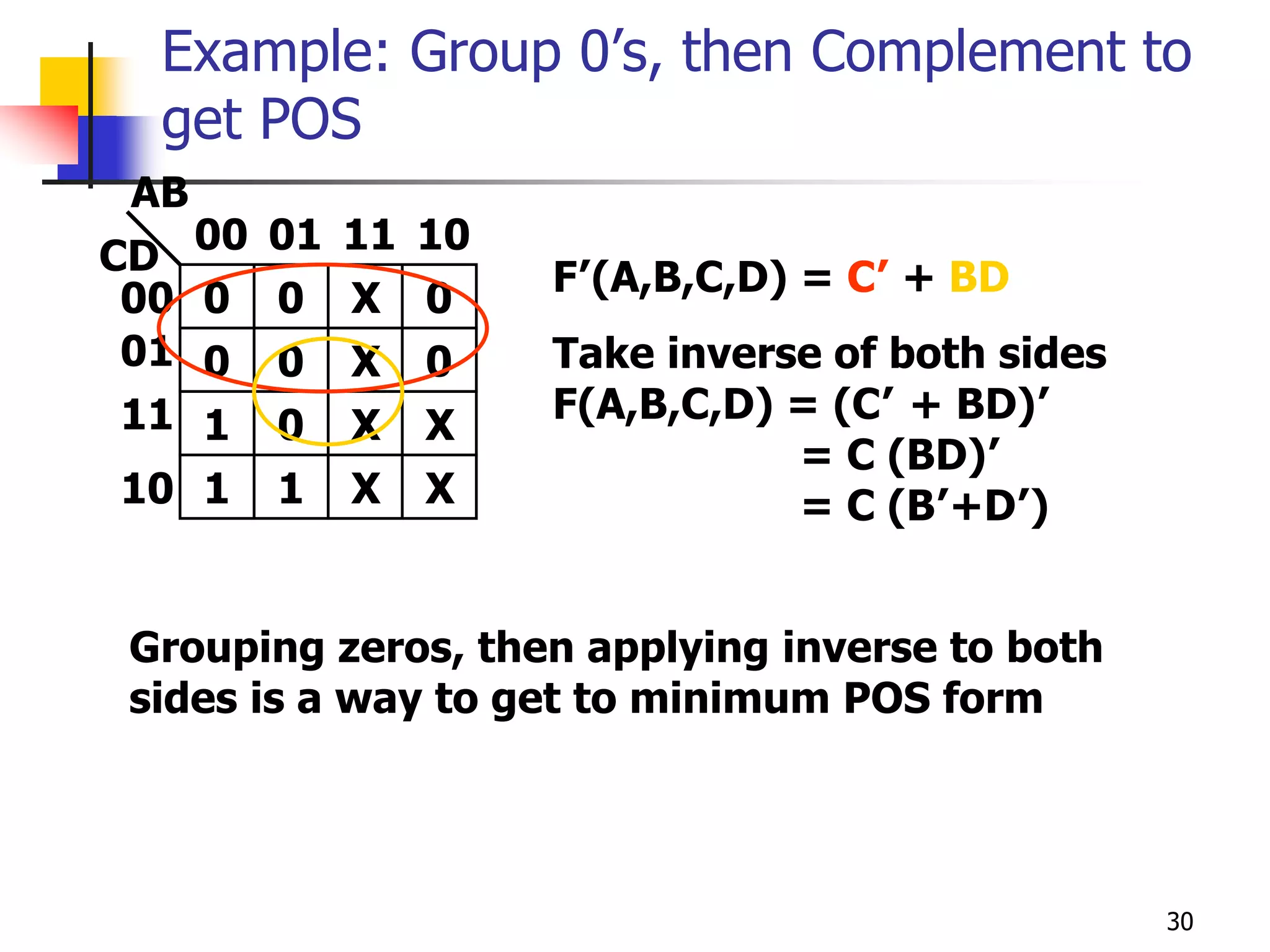
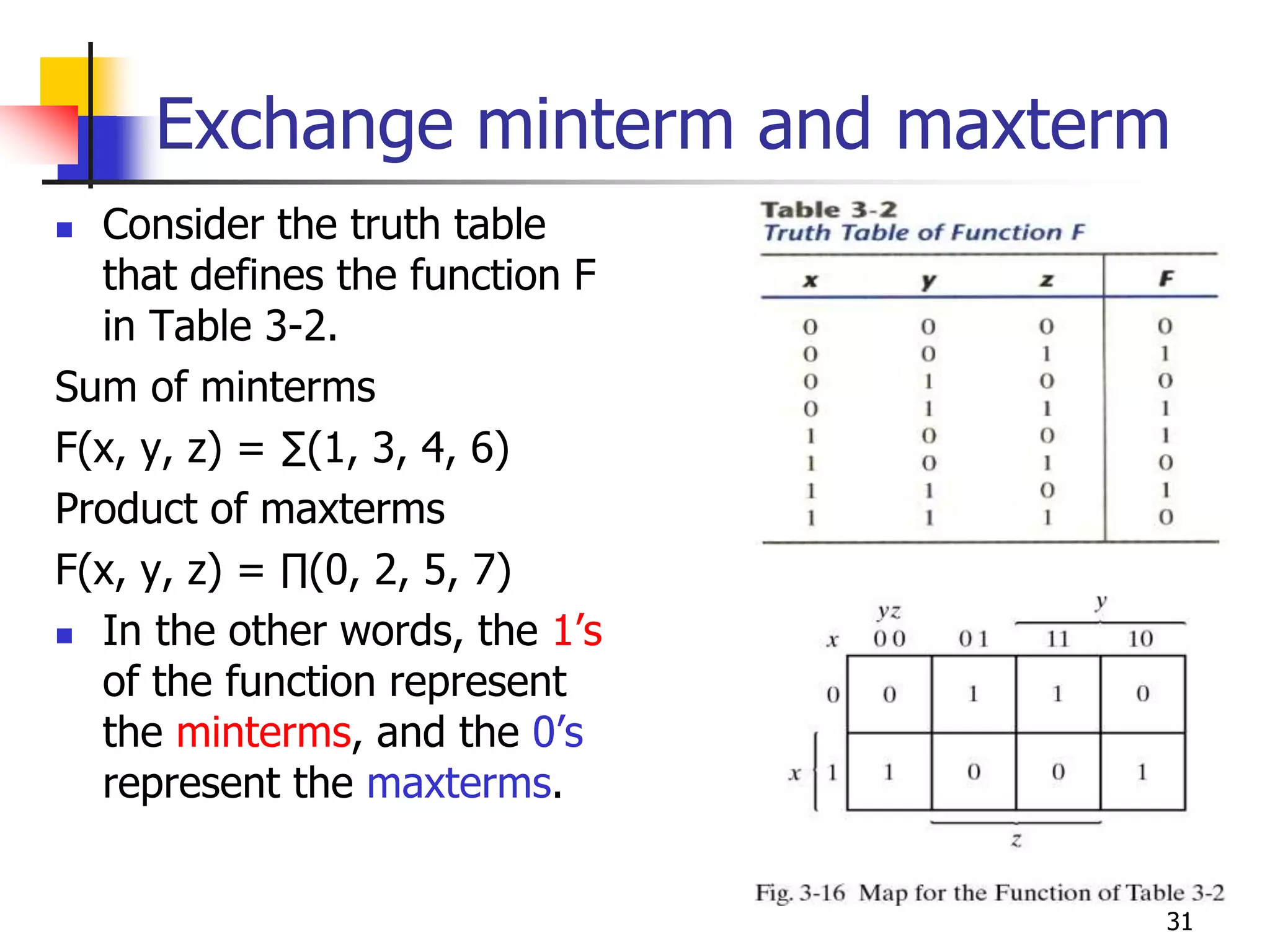
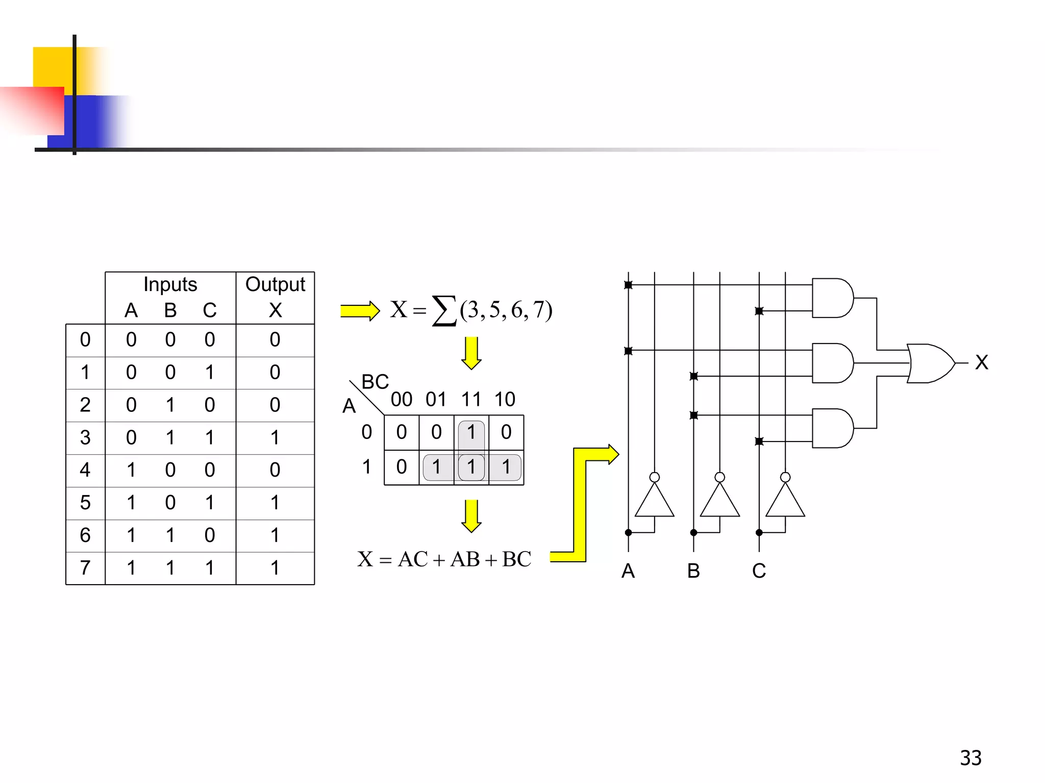
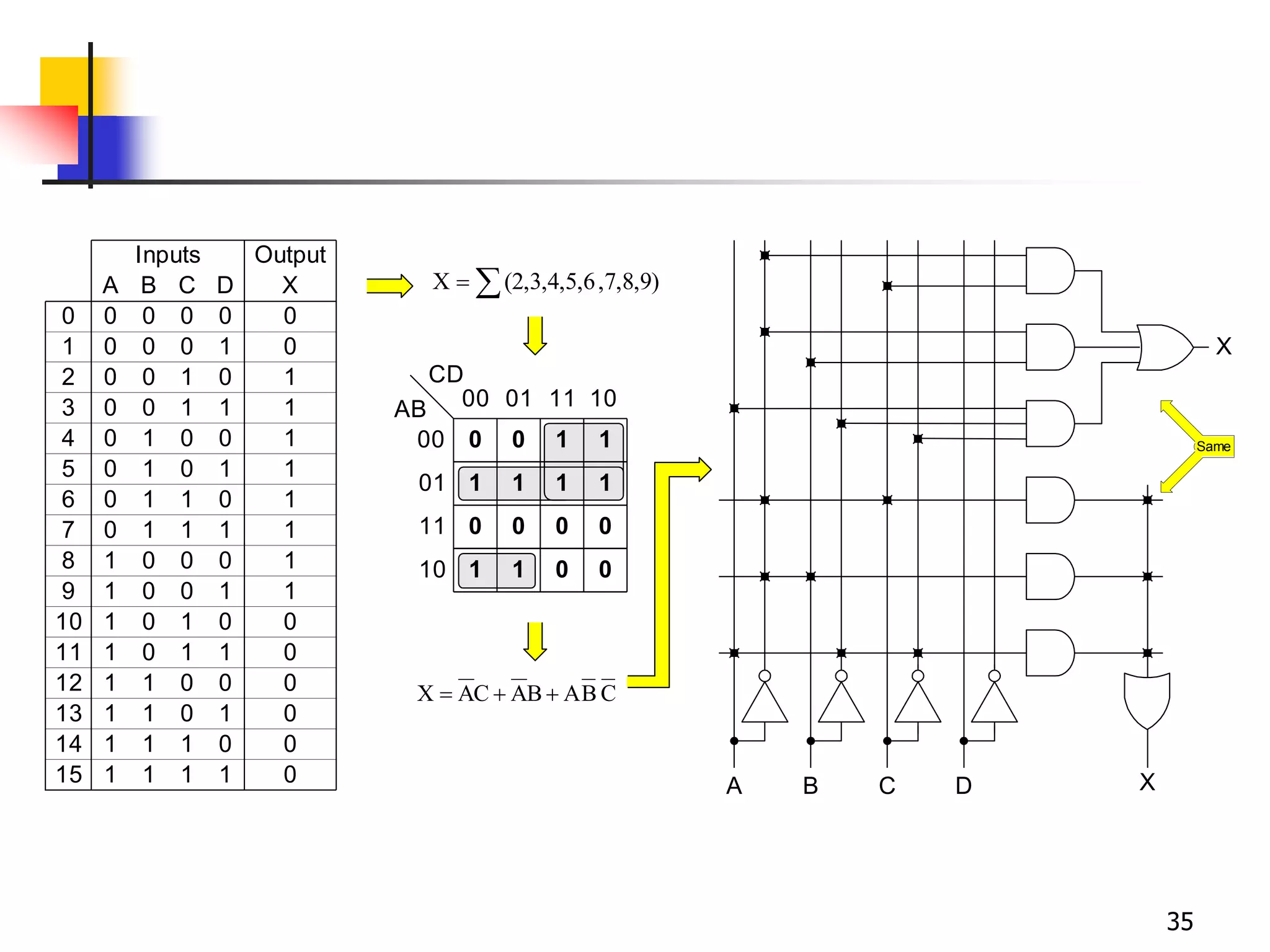
Karnaugh maps are a graphical method used to minimize logic functions. They arrange the minterms of a function in a grid based on the number of variables. Groupings of adjacent 1s in the map correspond to simplified logic terms. The largest possible groupings are used to find a minimum logic expression for the function. Don't cares can also be grouped and treated as 0s or 1s to further simplify expressions.
Digital logic circuits important question and answers for 5 unitsLekashri Subramanian
This document provides information about digital logic circuits and binary operations. It includes definitions of key terms like registers, register transfer, binary logic, logic gates, and parity bits. It also covers operations like subtraction using 2's and 1's complements, and reducing Boolean expressions using De Morgan's theorems, duality properties, and canonical forms.
The document provides information about digital logic circuits including definitions of binary logic, steps for binary to decimal and hexadecimal conversions, classification of binary codes, logic gates, combinational logic circuits like multiplexers, decoders, encoders, and comparators. It also includes properties of Boolean algebra and methods for minimizing Boolean functions using Karnaugh maps and Quine-McCluskey method. Various problems are given involving binary arithmetic, logic gate implementations, Boolean expressions and their simplification.
This document provides a summary of digital logic design concepts including combinational logic, Boolean equations, Karnaugh maps, hazards, and NAND/NOR representation. It discusses combinational logic, Boolean equation forms, using Karnaugh maps to minimize logic functions, hazards that can occur in combinational circuits, and ways to remove hazards. It also explains that any logic function can be realized using only NAND or NOR gates and how basic NAND and NOR gates can be implemented using transistors.
The document discusses digital electronics and Boolean algebra. It introduces basic logic operations such as AND, OR, and NOT. It then discusses additional logic operations like NAND, NOR, XOR, and XNOR. Truth tables are presented as a way to describe the functional behavior of Boolean expressions and logic circuits. Boolean expressions are composed of literals and logic operations. Boolean algebra laws and theorems can be used to simplify Boolean expressions, which allows for simpler circuit implementation.
The Karnaugh map method provides a graphical way to simplify logic equations or convert truth tables into logic circuits. It arranges variables in a grid so that adjacent squares differ in only one variable. Loops of adjacent 1s can then be identified to eliminate variables from the logic expression. Larger loops eliminate more variables - pairs eliminate one variable, quads eliminate two variables, and octets eliminate three variables. The method is demonstrated through examples of constructing Karnaugh maps from truth tables and simplifying the resulting logic expressions through looping.
The document discusses combinational circuits and components. It covers topics like magnitude comparators, adders, multiplexers, and how they can be implemented using logic gates. Specifically, it provides examples of a 4-bit magnitude comparator and 4-bit ripple carry adder. It also discusses the design and truth table of a 2-to-1 multiplexer. Project 2 details are announced which involves designing eight logic functions.
The document contains examples and solutions to problems involving boolean algebra, combinational logic circuits, binary number systems, and basic digital logic components like flip-flops. Some key points:
- It provides solutions to simplifying boolean expressions and designing combinational logic circuits from truth tables.
- Examples are given for binary coded decimal to seven segment decoding and frequency point calculations based on input frequency division.
- Conversions between binary, decimal, and hexadecimal number systems are demonstrated.
- The logic diagram, symbol, and truth table for an RS flip-flop implemented with NAND gates is illustrated.
This document contains 27 multiple choice questions regarding number systems, Boolean algebra, logic gates and digital circuits. The questions cover topics such as binary, hexadecimal and decimal conversions; Boolean expressions and logic functions; logic gates; and basic digital circuits. Sample questions include the decimal equivalent of a binary number, Boolean expressions for logic functions, minimum number of gates needed for an implementation, and output waveforms of simple circuits.
Karnaugh maps provide an alternative way to simplify logic circuits compared to Boolean algebra. A Karnaugh map arranges the 1s and 0s from a truth table into cells based on the number of variables. Adjacent cells containing 1s are grouped to find simplified logic expressions in a visual manner. Karnaugh maps are commonly used for 2, 3, or 4 variable problems by arranging the cells accordingly. They allow the logic relationships between variables to be visualized in order to minimize Boolean expressions.
Engineering electronics and electrical 3 K-Maps.pptxxenxavy2
Karnaugh maps (K-maps) are graphical representations used to simplify Boolean algebraic expressions. They allow minimizing Boolean expressions with 2 to 4 variables visually without using Boolean algebra theorems. K-maps arrange variables in a grid with each cell representing a minterm. Variables are assigned to rows and columns. Adjacent cells differ by only one variable. Groups of 1s are identified to find prime implicants and minimize the expression. Rules include grouping adjacent 1s, forming largest non-overlapping groups, and allowing overlapping and corner groups.
The document discusses Karnaugh maps (K-maps), which are a tool for representing and simplifying Boolean functions with up to six variables. K-maps arrange the variables in a grid with cells representing minterms or maxterms. Adjacent cells that are both 1s can be combined to eliminate variables. The document provides examples of constructing K-maps from Boolean expressions and using them to find minimum sum of products (SOP) and product of sums (POS) expressions.
The document discusses Karnaugh maps and their use in minimizing Boolean functions. Karnaugh maps arrange variables in a grid and use 1s and 0s to represent truth table outputs. Adjacent 1s that differ in only one variable can be combined to simplify the Boolean expression. Larger groups like quads and octets allow eliminating more variables. Karnaugh maps provide a visual way to minimize functions through identifying and combining adjacent terms.
digital logic design Chapter 2 boolean_algebra_&_logic_gatesImran Waris
The document discusses Boolean algebra and logic gates. It defines binary operators like AND, OR, and NOT. It covers Boolean algebra postulates and theorems including duality, DeMorgan's theorem, and absorption. Standard forms like sum of products and product of sums are presented. Common logic gates such as AND, OR, NAND, NOR, XOR, and XNOR are defined. Homework problems from a textbook are listed involving simplifying Boolean expressions, drawing logic diagrams, and converting expressions between canonical forms.
Karnaugh maps are a graphical technique used to simplify Boolean logic equations. They represent truth tables in a two-dimensional layout where physically adjacent cells imply logical adjacency. This adjacency allows common terms to be factored out to minimize logic expressions. Karnaugh maps are most commonly used to manually minimize logic with up to four variables into sum-of-products or product-of-sums form.
- There are two classes of logic circuits: combinational circuits and sequential circuits.
- A combinational circuit consists of logic gates where the output depends only on the current inputs.
- Common combinational circuits include arithmetic functions, data transmission functions, and code converters.
- Combinational circuits can be analyzed using Boolean functions and truth tables to determine the function and design circuits.
The document discusses Karnaugh maps (K-maps), which are a tool for representing and simplifying Boolean functions with up to six variables. K-maps arrange the variables in a grid according to their binary values. Adjacent cells that differ in only one variable can be combined to simplify the function by eliminating that variable. The document provides examples of using K-maps to minimize Boolean functions in sum of products and product of sums form. It also discusses techniques like combining cells into the largest groups possible and handling don't-care conditions to further simplify expressions.
Digital devices like computers, watches, and phones use binary numbers encoded as signals with two values, 0 and 1. Basic logic gates like AND, OR, and NOT are used to build more complex digital circuits. Boolean algebra describes the logic operations performed by these circuits using rules for binary true/false values. Circuits add binary numbers by performing full adder logic on corresponding bits with sum and carry outputs.
Karnaugh maps provide an alternative way to simplify logic circuits by visually grouping adjacent cells containing 1's and 0's in a map based on the truth table. The document provides examples of 2, 3, and 4 variable Karnaugh maps and explains how to construct the maps from truth tables and simplify logic functions into minimal Boolean expressions.
The document discusses obtaining the canonical disjunctive and conjunctive forms of a logic function. It provides an example logic table and determines the disjunctive and conjunctive forms. It then discusses Karnaugh maps as a graphical tool to simplify logic equations and minimize switching functions. It provides steps for constructing a Karnaugh map, including numbering cells and representing functions and cubes on the map. Finally, it gives an example of representing a logic function on a Karnaugh map.
Statistics Assignment 1 HET551 – Design and Developm.docxrafaelaj1
Statistics Assignment 1
HET551 – Design and Development Project 1
Michael Allwright
Haddon O’Neill
Tuesday, 24 May 2011
1 Normal Approximation to the Binomial Distribution
This section of the assignment shows how a normal curve can be used to approximate the binomial distribution. This
section of the assignment was completed using a MATLAB function (shown in Listings 1) which would generate and
save plots of the various Binomial Distributions after normalisation, and then calculate the errors between the standard
normal curve and the binomial distribution.
The plots in Figures 1 and 2 show the binomial distribution for various n trials with probability p = 1
3
and p = 1
2
respectively. These binomial plots have been normalised so that they can be compared with the standard normal
distribution.
From these plots it can be seen that once the binomial distribution has been normalised, the normal approximation is
a good approach to estimating the binomial distribution. To determine its accuracy, the data in Table 1 shows the
evaluation of qn = P(bn ≥ µn + 2σn) for both the normal curve and binomial distribution.
qn = P(bn ≥ µn + 2σn) Calculation Error
n N(0, 1) B(n, 1
2
) B(n, 1
3
) B(n, 1
2
) B(n, 1
3
)
1 0.0228 0.0000 0.0000 -0.02278 -0.02278
2 0.0228 0.0000 0.0000 -0.02278 -0.02278
3 0.0228 0.0000 0.0370 -0.02278 0.01426
4 0.0228 0.0000 0.0123 -0.02278 -0.01043
5 0.0228 0.0313 0.0453 0.00847 0.02249
10 0.0228 0.0107 0.0197 -0.01203 -0.00312
20 0.0228 0.0207 0.0376 -0.00208 0.01486
30 0.0228 0.0214 0.0188 -0.00139 -0.00398
40 0.0228 0.0192 0.0214 -0.00354 -0.00134
50 0.0228 0.0164 0.0222 -0.00636 -0.00059
100 0.0228 0.0176 0.0276 -0.00518 0.00479
Table 1: Calculating the error of the normal approximation to the binomial for various n and p
2 Analytical investigation of the Exponential Distribution
For this part of the assignment the density function shown in Equation 1 was given.
f(x) = λe−λx for x ≥ 0 and λ ≥ 0 (1)
Before any calculations were attempted, the area under graph was checked to show that
´∞
−∞f(x) dx = 1. That is
that the total probability of all possible values was 1.
2.1 Derivation of CDF
To find the CDF of the given function, the function was integrated with 0 and x being the lower and upper bound
respectively. This derivation is shown in Equations 2 to 4.
CDF =
ˆ x
o
f(x) dx =
ˆ x
o
λe−λx dx (2)
2
−5 −4 −3 −2 −1 0 1 2 3 4 5
0
0.05
0.1
0.15
0.2
0.25
0.3
0.35
0.4
0.45
0.5
Number of Successes (shifted left by u = 0.33)
P
ro
b
a
b
ili
ty
(a) n = 1
−5 −4 −3 −2 −1 0 1 2 3 4 5
0
0.05
0.1
0.15
0.2
0.25
0.3
0.35
0.4
0.45
0.5
Number of Successes (shifted left by u = 0.67)
P
ro
b
a
b
ili
ty
(b) n = 2
−5 −4 −3 −2 −1 0 1 2 3 4 5
0
0.05
0.1
0.15
0.2
0.25
0.3
0.35
0.4
0.45
0.5
Number of Successes (shifted left by u = 1.00)
P
ro
b
a
b
ili
ty
(c) n = 3
−5 −4 −3 −2 −1 0 1 2 3 4 5
0
0.05
0.1
0.15
0.2
0.25
0.3
0.35
0.4
0.45
0.5
Number of Successes.
This document provides an overview of Boolean algebra and logic simplification. It defines Boolean operations and variables, lists laws and rules of Boolean algebra including De Morgan's theorems. It also explains standard forms of Boolean expressions, truth tables, and how to use Karnaugh maps to minimize logic expressions in sum of products or product of sums form. Karnaugh maps allow grouping variables to simplify expressions for 2, 3, 4 or more variables.
The document provides an overview of digital logic circuits. It begins with an introduction to logic gates and Boolean algebra. Common logic gates like AND, OR, NAND, NOR, XOR and XNOR are described along with their truth tables. Boolean algebra is introduced as an algebra used for analysis and synthesis of digital logic circuits. Standard forms like sum of products and product of sums are discussed. Karnaugh maps are then described as a method for simplifying Boolean functions to minimize logic circuits. The document concludes with examples of map simplification using adjacent cells and combinations of multiple cells.
This is the entrance exam paper for ISI MSQE Entrance Exam for the year 2010. Much more information on the ISI MSQE Entrance Exam and ISI MSQE Entrance preparation help available on http://crackdse.com
This document discusses affine functions. It defines affine functions as functions of the form f(x) = ax + b, where a and b are real numbers. It provides examples of linear functions where b = 0, constant functions where a = 0, and the identity function where a = 1 and b = 0. It discusses the angular coefficient a and the linear coefficient b. It explains that the graph of an affine function is a straight line that can be increasing or decreasing. It also discusses finding the zero or root of an affine function and studying the sign of an affine function.
1. Write an equation in standard form of the parabola that has th.docxKiyokoSlagleis
1.
Write an equation in standard form of the parabola that has the same shape as the graph of f(x) = 2x
2
, but with the given point as the vertex (5, 3).
A. f(x) = (2x - 4) + 4
B. f(x) = 2(2x + 8) + 3
C. f(x) = 2(x - 5)
2
+ 3
D. f(x) = 2(x + 3)
2
+ 3
2 of 20
5.0 Points
Find the coordinates of the vertex for the parabola defined by the given quadratic function.
f(x) = 2(x - 3)
2
+ 1
A. (3, 1)
B. (7, 2)
C. (6, 5)
D. (2, 1)
3 of 20
5.0 Points
Find the vertical asymptotes, if any, and the values of x corresponding to holes, if any, of the graph of the following rational function.
g(x) = x + 3/x(x + 4)
A. Vertical asymptotes: x = 4, x = 0; holes at 3x
B. Vertical asymptotes: x = -8, x = 0; holes at x + 4
C. Vertical asymptotes: x = -4, x = 0; no holes
D. Vertical asymptotes: x = 5, x = 0; holes at x - 3
4 of 20
5.0 Points
"Y varies directly as the n
th
power of x" can be modeled by the equation:
A. y = kx
n
.
B. y = kx/n.
C. y = kx
*n
.
D. y = kn
x
.
5 of 20
5.0 Points
40 times a number added to the negative square of that number can be expressed as:
A.
A(x) = x
2
+ 20x.
B. A(x) = -x + 30x.
C.
A(x) = -x
2
- 60x.
D.
A(x) = -x
2
+ 40x.
6 of 20
5.0 Points
The graph of f(x) = -x
3
__________ to the left and __________ to the right.
A. rises; falls
B. falls; falls
C. falls; rises
D. falls; falls
Solve the following formula for the specified variable:
V = 1/3 lwh for h
7 of 20
Write an equation that expresses each relationship. Then solve the equation for y.
x varies jointly as y and z
A. x = kz; y = x/k
B. x = kyz; y = x/kz
C. x = kzy; y = x/z
D. x = ky/z; y = x/zk
8 of 20
8 times a number subtracted from the squared of that number can be expressed as:
A. P(x) = x + 7x.
B.P(x) = x
2
- 8x.
C. P(x) = x - x.
P(x) = x
2
+ 10x.
9of 20
Find the x-intercepts. State whether the graph crosses the x-axis, or touches the x-axis and turns around, at each intercept.
f(x) = x
4
- 9x
2
A. x = 0, x = 3, x = -3; f(x) crosses the x-axis at -3 and 3; f(x) touches the x-axis at 0.
B. x = 1, x = 2, x = 3; f(x) crosses the x-axis at 2 and 3; f(x) crosses the x-axis at 0.
C. x = 0, x = -3, x = 5; f(x) touches the x-axis at -3 and 5; f(x) touches the x-axis at 0.
D. x = 1, x = 2, x = -4; f(x) crosses the x-axis at 2 and -4; f(x) touches the x-axis at 0.
10 of 20
Find the domain of the following rational function.
f(x) = x + 7/x
2
+ 49
A. All real numbers < 69
B. All real numbers > 210
C. All real numbers ≤ 77
D. All real numbers
11 of 20
Write an equation in standard form of the parabola that has the same shape as the graph of f(x) = 3x
2
or g(x) = -3x
2
, but with the given maximum or minimum.
Minimum = 0 at x = 11
A. f(x) = 6(x - 9)
B. f(x) = 3(x - 11)
2
C. f(x) = 4(x + 10)
D. f(x) = 3(x
2
- 15)
2
12 of 20
Solve the following polynomial inequality.
3x
2
+ 10x - 8 ≤ 0
A. [6, 1/3]
B. [-4, 2/3]
C. [-9, 4/5]
D. [8, 2/7]
13 of 20
Find the coordinate.
A SYSTEMATIC RISK ASSESSMENT APPROACH FOR SECURING THE SMART IRRIGATION SYSTEMSIJNSA Journal
The smart irrigation system represents an innovative approach to optimize water usage in agricultural and landscaping practices. The integration of cutting-edge technologies, including sensors, actuators, and data analysis, empowers this system to provide accurate monitoring and control of irrigation processes by leveraging real-time environmental conditions. The main objective of a smart irrigation system is to optimize water efficiency, minimize expenses, and foster the adoption of sustainable water management methods. This paper conducts a systematic risk assessment by exploring the key components/assets and their functionalities in the smart irrigation system. The crucial role of sensors in gathering data on soil moisture, weather patterns, and plant well-being is emphasized in this system. These sensors enable intelligent decision-making in irrigation scheduling and water distribution, leading to enhanced water efficiency and sustainable water management practices. Actuators enable automated control of irrigation devices, ensuring precise and targeted water delivery to plants. Additionally, the paper addresses the potential threat and vulnerabilities associated with smart irrigation systems. It discusses limitations of the system, such as power constraints and computational capabilities, and calculates the potential security risks. The paper suggests possible risk treatment methods for effective secure system operation. In conclusion, the paper emphasizes the significant benefits of implementing smart irrigation systems, including improved water conservation, increased crop yield, and reduced environmental impact. Additionally, based on the security analysis conducted, the paper recommends the implementation of countermeasures and security approaches to address vulnerabilities and ensure the integrity and reliability of the system. By incorporating these measures, smart irrigation technology can revolutionize water management practices in agriculture, promoting sustainability, resource efficiency, and safeguarding against potential security threats.
Electric vehicle and photovoltaic advanced roles in enhancing the financial p...IJECEIAES
Climate change's impact on the planet forced the United Nations and governments to promote green energies and electric transportation. The deployments of photovoltaic (PV) and electric vehicle (EV) systems gained stronger momentum due to their numerous advantages over fossil fuel types. The advantages go beyond sustainability to reach financial support and stability. The work in this paper introduces the hybrid system between PV and EV to support industrial and commercial plants. This paper covers the theoretical framework of the proposed hybrid system including the required equation to complete the cost analysis when PV and EV are present. In addition, the proposed design diagram which sets the priorities and requirements of the system is presented. The proposed approach allows setup to advance their power stability, especially during power outages. The presented information supports researchers and plant owners to complete the necessary analysis while promoting the deployment of clean energy. The result of a case study that represents a dairy milk farmer supports the theoretical works and highlights its advanced benefits to existing plants. The short return on investment of the proposed approach supports the paper's novelty approach for the sustainable electrical system. In addition, the proposed system allows for an isolated power setup without the need for a transmission line which enhances the safety of the electrical network
A review on techniques and modelling methodologies used for checking electrom...nooriasukmaningtyas
The proper function of the integrated circuit (IC) in an inhibiting electromagnetic environment has always been a serious concern throughout the decades of revolution in the world of electronics, from disjunct devices to today’s integrated circuit technology, where billions of transistors are combined on a single chip. The automotive industry and smart vehicles in particular, are confronting design issues such as being prone to electromagnetic interference (EMI). Electronic control devices calculate incorrect outputs because of EMI and sensors give misleading values which can prove fatal in case of automotives. In this paper, the authors have non exhaustively tried to review research work concerned with the investigation of EMI in ICs and prediction of this EMI using various modelling methodologies and measurement setups.
Redefining brain tumor segmentation: a cutting-edge convolutional neural netw...IJECEIAES
Medical image analysis has witnessed significant advancements with deep learning techniques. In the domain of brain tumor segmentation, the ability to
precisely delineate tumor boundaries from magnetic resonance imaging (MRI)
scans holds profound implications for diagnosis. This study presents an ensemble convolutional neural network (CNN) with transfer learning, integrating
the state-of-the-art Deeplabv3+ architecture with the ResNet18 backbone. The
model is rigorously trained and evaluated, exhibiting remarkable performance
metrics, including an impressive global accuracy of 99.286%, a high-class accuracy of 82.191%, a mean intersection over union (IoU) of 79.900%, a weighted
IoU of 98.620%, and a Boundary F1 (BF) score of 83.303%. Notably, a detailed comparative analysis with existing methods showcases the superiority of
our proposed model. These findings underscore the model’s competence in precise brain tumor localization, underscoring its potential to revolutionize medical
image analysis and enhance healthcare outcomes. This research paves the way
for future exploration and optimization of advanced CNN models in medical
imaging, emphasizing addressing false positives and resource efficiency.
Harnessing WebAssembly for Real-time Stateless Streaming PipelinesChristina Lin
Traditionally, dealing with real-time data pipelines has involved significant overhead, even for straightforward tasks like data transformation or masking. However, in this talk, we’ll venture into the dynamic realm of WebAssembly (WASM) and discover how it can revolutionize the creation of stateless streaming pipelines within a Kafka (Redpanda) broker. These pipelines are adept at managing low-latency, high-data-volume scenarios.
Embedded machine learning-based road conditions and driving behavior monitoringIJECEIAES
Car accident rates have increased in recent years, resulting in losses in human lives, properties, and other financial costs. An embedded machine learning-based system is developed to address this critical issue. The system can monitor road conditions, detect driving patterns, and identify aggressive driving behaviors. The system is based on neural networks trained on a comprehensive dataset of driving events, driving styles, and road conditions. The system effectively detects potential risks and helps mitigate the frequency and impact of accidents. The primary goal is to ensure the safety of drivers and vehicles. Collecting data involved gathering information on three key road events: normal street and normal drive, speed bumps, circular yellow speed bumps, and three aggressive driving actions: sudden start, sudden stop, and sudden entry. The gathered data is processed and analyzed using a machine learning system designed for limited power and memory devices. The developed system resulted in 91.9% accuracy, 93.6% precision, and 92% recall. The achieved inference time on an Arduino Nano 33 BLE Sense with a 32-bit CPU running at 64 MHz is 34 ms and requires 2.6 kB peak RAM and 139.9 kB program flash memory, making it suitable for resource-constrained embedded systems.
Comparative analysis between traditional aquaponics and reconstructed aquapon...bijceesjournal
The aquaponic system of planting is a method that does not require soil usage. It is a method that only needs water, fish, lava rocks (a substitute for soil), and plants. Aquaponic systems are sustainable and environmentally friendly. Its use not only helps to plant in small spaces but also helps reduce artificial chemical use and minimizes excess water use, as aquaponics consumes 90% less water than soil-based gardening. The study applied a descriptive and experimental design to assess and compare conventional and reconstructed aquaponic methods for reproducing tomatoes. The researchers created an observation checklist to determine the significant factors of the study. The study aims to determine the significant difference between traditional aquaponics and reconstructed aquaponics systems propagating tomatoes in terms of height, weight, girth, and number of fruits. The reconstructed aquaponics system’s higher growth yield results in a much more nourished crop than the traditional aquaponics system. It is superior in its number of fruits, height, weight, and girth measurement. Moreover, the reconstructed aquaponics system is proven to eliminate all the hindrances present in the traditional aquaponics system, which are overcrowding of fish, algae growth, pest problems, contaminated water, and dead fish.
KuberTENes Birthday Bash Guadalajara - K8sGPT first impressionsVictor Morales
K8sGPT is a tool that analyzes and diagnoses Kubernetes clusters. This presentation was used to share the requirements and dependencies to deploy K8sGPT in a local environment.
DEEP LEARNING FOR SMART GRID INTRUSION DETECTION: A HYBRID CNN-LSTM-BASED MODELgerogepatton
As digital technology becomes more deeply embedded in power systems, protecting the communication
networks of Smart Grids (SG) has emerged as a critical concern. Distributed Network Protocol 3 (DNP3)
represents a multi-tiered application layer protocol extensively utilized in Supervisory Control and Data
Acquisition (SCADA)-based smart grids to facilitate real-time data gathering and control functionalities.
Robust Intrusion Detection Systems (IDS) are necessary for early threat detection and mitigation because
of the interconnection of these networks, which makes them vulnerable to a variety of cyberattacks. To
solve this issue, this paper develops a hybrid Deep Learning (DL) model specifically designed for intrusion
detection in smart grids. The proposed approach is a combination of the Convolutional Neural Network
(CNN) and the Long-Short-Term Memory algorithms (LSTM). We employed a recent intrusion detection
dataset (DNP3), which focuses on unauthorized commands and Denial of Service (DoS) cyberattacks, to
train and test our model. The results of our experiments show that our CNN-LSTM method is much better
at finding smart grid intrusions than other deep learning algorithms used for classification. In addition,
our proposed approach improves accuracy, precision, recall, and F1 score, achieving a high detection
accuracy rate of 99.50%.
CHINA’S GEO-ECONOMIC OUTREACH IN CENTRAL ASIAN COUNTRIES AND FUTURE PROSPECTjpsjournal1
The rivalry between prominent international actors for dominance over Central Asia's hydrocarbon
reserves and the ancient silk trade route, along with China's diplomatic endeavours in the area, has been
referred to as the "New Great Game." This research centres on the power struggle, considering
geopolitical, geostrategic, and geoeconomic variables. Topics including trade, political hegemony, oil
politics, and conventional and nontraditional security are all explored and explained by the researcher.
Using Mackinder's Heartland, Spykman Rimland, and Hegemonic Stability theories, examines China's role
in Central Asia. This study adheres to the empirical epistemological method and has taken care of
objectivity. This study analyze primary and secondary research documents critically to elaborate role of
china’s geo economic outreach in central Asian countries and its future prospect. China is thriving in trade,
pipeline politics, and winning states, according to this study, thanks to important instruments like the
Shanghai Cooperation Organisation and the Belt and Road Economic Initiative. According to this study,
China is seeing significant success in commerce, pipeline politics, and gaining influence on other
governments. This success may be attributed to the effective utilisation of key tools such as the Shanghai
Cooperation Organisation and the Belt and Road Economic Initiative.
CHINA’S GEO-ECONOMIC OUTREACH IN CENTRAL ASIAN COUNTRIES AND FUTURE PROSPECT
Chapter-3.ppt
1. 1
Chapter 3 Gate-Level
Minimization
A Karnaugh map is a graphical method used to
obtained the most simplified form of an expression
in a standard form (Sum-of-Products or Product-of-
Sums
The map is made up of squares, with each square
representing one minterm of the function.
This produces a circuit diagram with a minimum
number of gates and the minimum number of
inputs to the gate.
It is sometimes possible to find two or more
expressions that satisfy the minimization criteria.
2. What are Karnaugh1 maps?
Karnaugh maps provide an alternative way of
simplifying logic circuits.
Instead of using Boolean algebra simplification
techniques, you can transfer logic values from a
Boolean statement or a truth table into a Karnaugh
map.
The arrangement of 0's and 1's within the map
helps you to visualise the logic relationships
between the variables and leads directly to a
simplified Boolean statement.
1Named for the American electrical engineer Maurice Karnaugh.
3. Karnaugh maps
Karnaugh maps, or K-maps, are often used to simplify logic problems
with 2, 3 or 4 variables.
B
A
For the case of 2 variables, we form a map consisting
of 22=4 cells as shown in Figure
A
B 0 1
0
1
Cell = 2n ,where n is a number of variables
00 10
01 11
A
B 0 1
0
1
A
B 0 1
0
1
B
A
B
A AB
B
A B
A
B
A B
A
Maxterm Minterm
0 2
1 3
4. Karnaugh maps
3 variables Karnaugh map
AB
C 00 01 11 10
0
1
C
B
A C
B
A C
AB C
B
A
C
B
A BC
A ABC C
B
A
0 1 3 2
6
5
4 7
Cell = 23=8
6. 6
Five-variable map
Fig.3-12, the left-hand four-variable map represents the 16 squares
where A=0, and the other four-variable map represents the squares
where A=1.
In addition, each square in the A=0 map is adjacent to the
corresponding square in the A=1 map.
7. The Karnaugh map is completed by entering a
'1‘(or ‘0’) in each of the appropriate cells.
Within the map, adjacent cells containing 1's (or
0’s) are grouped together in twos, fours, or
eights.
Karnaugh maps
8. 8
Example: Groupings on 3-Variable K-Maps
1
1 0
1 0
00
BC
0
0 0
0 0
01
11
10
F(A,B,C) = A’B’
A
1
1 1
1 1
00
BC
0
0 0
0 0
01
11
10
F(A,B,C) = B’
A
1
1 1
0 0
00
BC
0
0 0
1
01
11
10
F(A,B,C) = C’
1
Remember that
top and bottom
of map are
adjacent
9. 9
Example: Multiple Groupings
1
1 0
1 1
00
BC
0
0 0
0 0
01
11
10
Want to cover all ‘1’s with
largest possible
groupings.
F(A,B,C) = B’C + A’B’
1
0 1
0 0
00
BC
0
1 0
1 0
01
11
10
Groupings of only a single ‘1’
are ok if larger groupings
cannot be found.
F(A,B,C) = AB’C’ + A’B
A
A
10. 10
Illegal Groupings
1
1 0
0 1
00
BC
0
0 0
0 0
01
11
10
A
Illegal Grouping!
Minterms are not boolean
adjacent!
A’B’C’ , AB’C will NOT reduce
to a single product term
A’B’C’ + AB’C = B’(A’C’+AC)
Valid groupings will always be a power of 2.
(will cover 1, 2, 4, 8, etc. minterms).
12. 12
AB
01
1 0
1 0
00
CD
00
1 0
1 0
01
11
10
0 1
0 1
0 1
0 1
11 10
F (A,B,C,D) = B’
Example: Groupings on four Variable Map
13. 13
More than one way to group…..
AB
01
1 1
1 0
00
CD
00
1 0
1 1
01
11
10
1 1
0 1
0 1
1 1
11 10 F (A,B,C,D) = B’D + C’D’ +
CD’
AB
01
1 1
1 0
00
CD
00
1 0
1 1
01
11
10
1 1
0 1
0 1
1 1
11 10
F (A,B,C,D) = B’ + D’
Want LARGEST groupings
that can cover ‘1’s.
14. 14
Two Solutions
AB
01
1 1
1 1
00
CD
00
0 1
0 0
01
11
10
0 0
0 0
1 1
0 0
11 10
EACH solution is equally
valid.
F(A,B,C,D) = A’C’ + ACD +
A’BD
AB
01
1 1
1 1
00
CD
00
0 1
0 0
01
11
10
0 0
0 0
1 1
0 0
11 10
F(A,B,C,D) = A’C’ + ACD +
BCD
Essential
PIs
Non-
Essential
PIs
15. Don't Care Conditions
There may be a combination of input values which
will never occur
if they do occur, the output is of no concern.
The function value for such combinations is called a
don't care.
They are denoted with x or –. Each x may be
arbitrarily assigned the value 0 or 1 in an
implementation.
Don’t cares can be used to further simplify a
function
2023/1/18 Boolean Algebra PJF - 15
16. 16
Example: Don’t Cares
Recall that Don’t
Cares are labeled as
‘X’s in truth table.
Can treat X’s as
either ‘0’s or ‘1’s
Row A B C D F(A,B,C,D)
0 0 0 0 0 0
1 0 0 0 1 0
2 0 0 1 0 1
3 0 0 1 1 1
4 0 1 0 0 0
5 0 1 0 1 0
6 0 1 1 0 1
7 0 1 1 1 0
8 1 0 0 0 0
9 1 0 0 1 0
10 1 0 1 0 x
11 1 0 1 1 x
12 1 1 0 0 x
13 1 1 0 1 x
14 1 1 1 0 x
15 1 1 1 1 x
F(ABCD)
Recognize BCD
numbers: 2,3,6
A
B
C
D
Non-BCD numbers are
don’t cares because will
never be applied as
inputs.
F
17. 17
Don’t Cares treated as ‘0’s or ‘1’s
AB
01
0 0
0 0
00
CD
00
1 0
1 1
01
11
10
X 0
X 0
X X
X X
11 10
Treat X’s as 1’s when
can get a larger
grouping. (Not all
X’s need to be
covered.)
F(A,B,C,D) = CD’ + B’C
18. 18
Example: Minimizing ‘0’s
1
1 1
0 0
00
BC
0
0 0
1
01
11
10
F(A,B,C) = C’
1
Grouping ‘0’s produces an
equation for F’.
F’(A,B,C) = C
20. Exercise
20
C
B
(0,4)
f
B
A
(4,5)
f
B
(0,1,4,5)
f
A
(0,1,2,3)
f
BC
00
0
01
1
11 10
A
1 0 0 0
1 0 0 0
BC
00
0
01
1
11 10
A
0 0 0 0
1 1 0 0
BC
00
0
01
1
11 10
A
1 1 1 1
0 0 0 0
BC
00
0
01
1
11 10
A
1 1 0 0
1 1 0 0
C
A
(0,4)
f
C
A
(4,6)
f
C
A
(0,2)
f
C
(0,2,4,6)
f
BC
00
0
01
1
11 10
A
0 1 1 0
0 0 0 0
BC
00
0
01
1
11 10
A
0 0 0 0
1 0 0 1
BC
00
0
01
1
11 10
A
1 0 0 1
1 0 0 1
BC
00
0
01
1
11 10
A
1 0 0 1
0 0 0 0
22. Exercise
22
D
C
B
(0,8)
f
D
C
B
(5,13)
f
D
B
A
(13,15)
f
D
B
A
(4,6)
f
C
A
(2,3,6,7)
f
D
B
)
(4,6,12,14
f
C
B
)
(2,3,10,11
f
D
B
(0,2,8,10)
f
CD
00
00
01
01
11
11
10
10
AB
1 0 0 0
0 0 0 0
0 0 0 0
1 0 0 0
CD
00
00
01
01
11
11
10
10
AB
0 0 0 0
0 1 0 0
0 1 0 0
0 0 0 0
CD
00
00
01
01
11
11
10
10
AB
0 0 0 0
0 0 0 0
0 1 1 0
0 0 0 0
CD
00
00
01
01
11
11
10
10
AB
0 0 0 0
1 0 0 1
0 0 0 0
0 0 0 0
CD
00
00
01
01
11
11
10
10
AB
0 0 1 1
0 0 1 1
0 0 0 0
0 0 0 0
CD
00
00
01
01
11
11
10
10
AB
0 0 0 0
1 0 0 1
1 0 0 1
0 0 0 0
CD
00
00
01
01
11
11
10
10
AB
0 0 1 1
0 0 0 0
0 0 0 0
0 0 1 1
CD
00
00
01
01
11
11
10
10
AB
1 0 0 1
0 0 0 0
0 0 0 0
1 0 0 1
23. Exercise
23
CD
00
00
01
01
11
11
10
10
AB
0 0 0 0
1 1 1 1
0 0 0 0
0 0 0 0
CD
00
00
01
01
11
11
10
10
AB
0 0 1 0
0 0 1 0
0 0 1 0
0 0 1 0
CD
00
00
01
01
11
11
10
10
AB
1 0 1 0
0 1 0 1
1 0 1 0
0 1 0 1
CD
00
00
01
01
11
11
10
10
AB
0 1 0 1
1 0 1 0
0 1 0 1
1 0 1 0
CD
00
00
01
01
11
11
10
10
AB
0 1 1 0
0 1 1 0
0 1 1 0
0 1 1 0
CD
00
00
01
01
11
11
10
10
AB
1 0 0 1
1 0 0 1
1 0 0 1
1 0 0 1
CD
00
00
01
01
11
11
10
10
AB
0 0 0 0
1 1 1 1
1 1 1 1
0 0 0 0
CD
00
00
01
01
11
11
10
10
AB
1 1 1 1
0 0 0 0
0 0 0 0
1 1 1 1
f (4,5,6,7) A B
f (3,7,11,15) C D
f (0,3,5,6,9,10,12,15)
f (1,2,4,7,8,11,13,14)
f A B C D
f A B C D
f (1,3,5,7,9,11,13,15)
f (0,2,4,6,8,10,12,14)
f (4,5,6,7,12,13,14,15)
f (0,1,2,3,8,9,10,11)
f D
f D
f B
f B
24. 24
Example
Ex. 3-7 F(A, B, C, D, E) = (0, 2, 4, 6, 9, 13, 21, 23, 25, 29, 31)
Because of both parts of the map have the common term (A’BD’E+ABD’E)
so the sum of products is
F = A’B’E’ + BD’E + ACE
common
25. 25
3-5. Don’t care conditions
Ex.3-9 Simplify the F (w, x, y, z)= ∑(1, 3, 7, 11, 15) with
don’t-care conditions d(w, x, y, z) = ∑(0, 2, 5)
In part (a) with minterms 0 and 2 F = yz + w’x’
In part (b) with minterm 5 F = yz + w’z
26. Example Don’t care
Simplify the function f(a,b,c,d)
whose K-map is shown at the
right.
f = a’c’d+ab’+cd’+a’bc’
or
f = a’c’d+ab’+cd’+a’bd’
2023/1/18 Boolean Algebra PJF - 26
x
x
1
1
x
x
0
0
1
0
1
1
1
0
1
0
x
x
1
1
x
x
0
0
1
0
1
1
1
0
1
0
0 1 0 1
1 1 0 1
0 0 x x
1 1 x x
ab
cd
00
01
11
10
00 01 11 10
27. Another Example
Simplify the function
g(a,b,c,d) whose K-map
is shown at right.
g = a’c’+ ab
or
g = a’c’+b’d
2023/1/18 Boolean Algebra PJF - 27
x 1 0 0
1 x 0 x
1 x x 1
0 x x 0
x 1 0 0
1 x 0 x
1 x x 1
0 x x 0
x 1 0 0
1 x 0 x
1 x x 1
0 x x 0
ab
cd
28. 28
3-4. Product of sums
simplification
If we mark the empty squares by 0’s rather than
1’s and combine them into valid adjacent squares,
we obtain the complement of the function, F’. Use
the DeMorgan’s theorem, we can get the product
of sums.
Ex.3-8 Simplify the Boolean function in
(a) sum of products
(b) product of sums
F(A, B, C, D) = ∑(0, 1, 2, 5, 8, 9, 10)
30. 30
Example: Group 0’s, then Complement to
get POS
AB
01
0 0
0 0
00
CD
00
1 0
1 1
01
11
10
X 0
X 0
X X
X X
11 10
F’(A,B,C,D) = C’ + BD
Take inverse of both sides
F(A,B,C,D) = (C’ + BD)’
= C (BD)’
= C (B’+D’)
Grouping zeros, then applying inverse to both
sides is a way to get to minimum POS form
31. 31
Exchange minterm and maxterm
Consider the truth table
that defines the function F
in Table 3-2.
Sum of minterms
F(x, y, z) = ∑(1, 3, 4, 6)
Product of maxterms
F(x, y, z) = ∏(0, 2, 5, 7)
In the other words, the 1’s
of the function represent
the minterms, and the 0’s
represent the maxterms.
32. Practice 1:Combinational circuit Design
Example: Design a 3-input (A,B,C) digital
circuit that will give at its output (X) a logic 1
only if the binary number formed at the
input has more ones than zeros.
32
33. 33
BC
AB
AC
X
A B C
0
0
0
0
0
0
0
0
0
0
0
0
1
1
1
1
1
1
1
1
1
1
1
1
X
0
0
0
1
0
1
1
1
Inputs Output
0
1
2
3
4
5
6
7
BC
00
0
01
1
11 10
A
0 0 1 0
0 1 1 1
A B C
X
7)
6,
5,
(3,
X
34. Practice 2:Combinational circuit Design
34
Example: Design a 4-input (A,B,C,D) digital circuit that will give at its
output (X) a logic 1 only if the binary number formed at the input is
between 2 and 9 (including).
35. 35
C
B
A
B
A
C
A
X
A B C
X
,7,8,9)
(2,3,4,5,6
X
A B C
0
0
0
0
0
1
X
0
0
Inputs Output
0
1
D
0
0
0 0 0 1
2 1
0 0 1 1
3 1
0 1 0 1
4 0
0 1 1 1
5 0
0 1 0 1
6 1
0 1 1 1
7 1
1 0 0 1
8 0
1 0 1 1
9 0
1 0 0 0
10 1
1 0 1 0
11 1
1 1 0 0
12 0
1 1 1 0
13 0
1 1 0 0
14 1
1 1 1 0
15 1 D
CD
00
00
01
01
11
11
10
10
AB
0 0 1 1
1 1 1 1
0 0 0 0
1 1 0 0
X
Same
36. Exercise
Design logic circuit that convert a 4-bits binary code to Excess-3 code
A B C D W X Y Z
0 0 0 0 0 0 1 1
0 0 0 1 0 1 0 0
0 0 1 0 0 1 0 1
0 0 1 1 0 1 1 0
0 1 0 0 0 1 1 1
0 1 0 1 1 0 0 0
0 1 1 0 1 0 0 1
0 1 1 1 1 0 1 0
1 0 0 0 1 0 1 1
1 0 0 1 1 1 0 0
1 0 1 0 x x x x
1 0 1 1 x x x x
1 1 0 0 x x x x
1 1 0 1 x x x x
1
1
1
1
1
1
0
1
x
X
X
X
X
x
X
x