Downloaded 250 times

![Simulation
Simulink scopes
Code debugging
Data analysis in MATLAB
Magnitude [dB]
0
-50
-100
-150
-200
-250
0
1000
2000
3000
Frequency [kHz]
4000
5000
0
1000
2000
3000
Frequency [kHz]
4000
5000
Phase [Degrees]
0
-1000
-2000
-3000
23](https://image.slidesharecdn.com/mbdembeddedworld-140305141020-phpapp02/75/Model-Based-Design-For-Motor-Control-Development-23-2048.jpg)
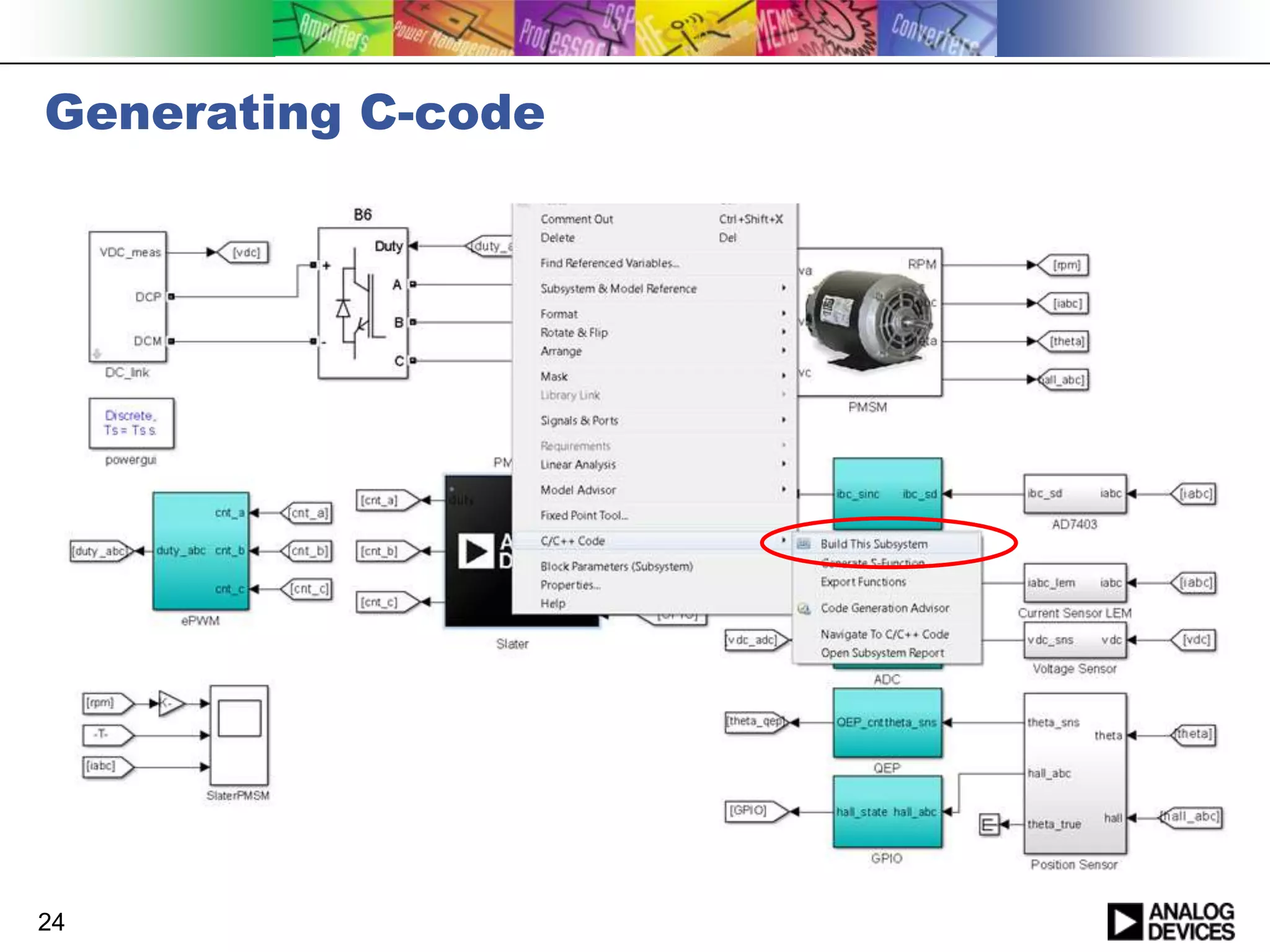
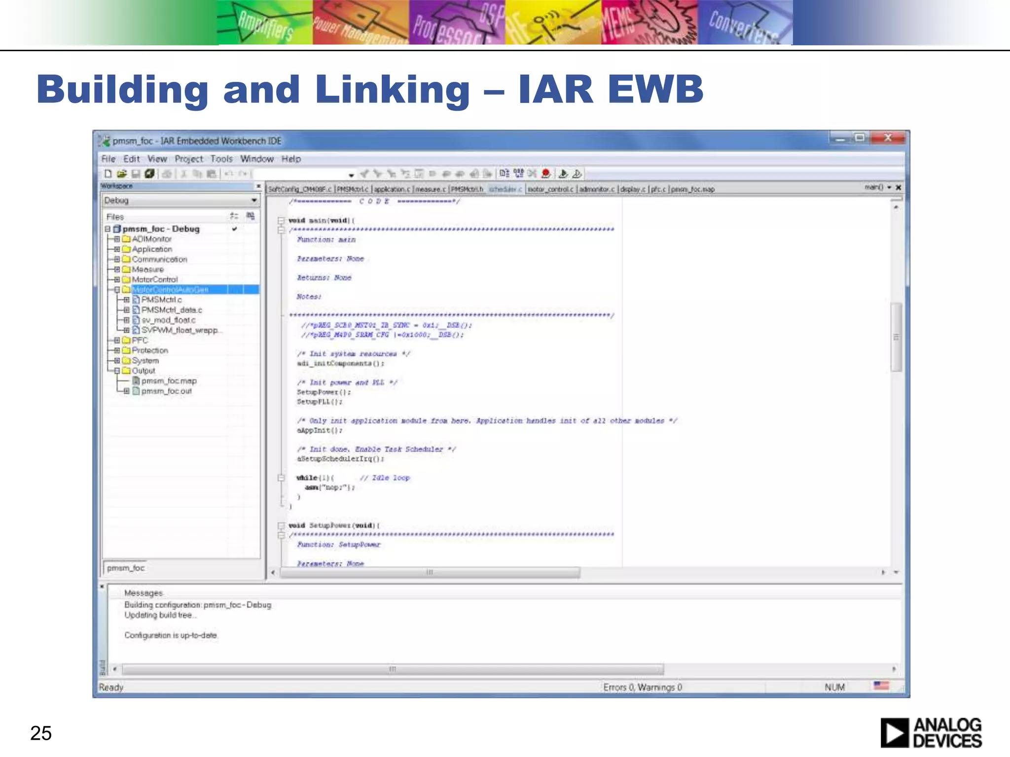
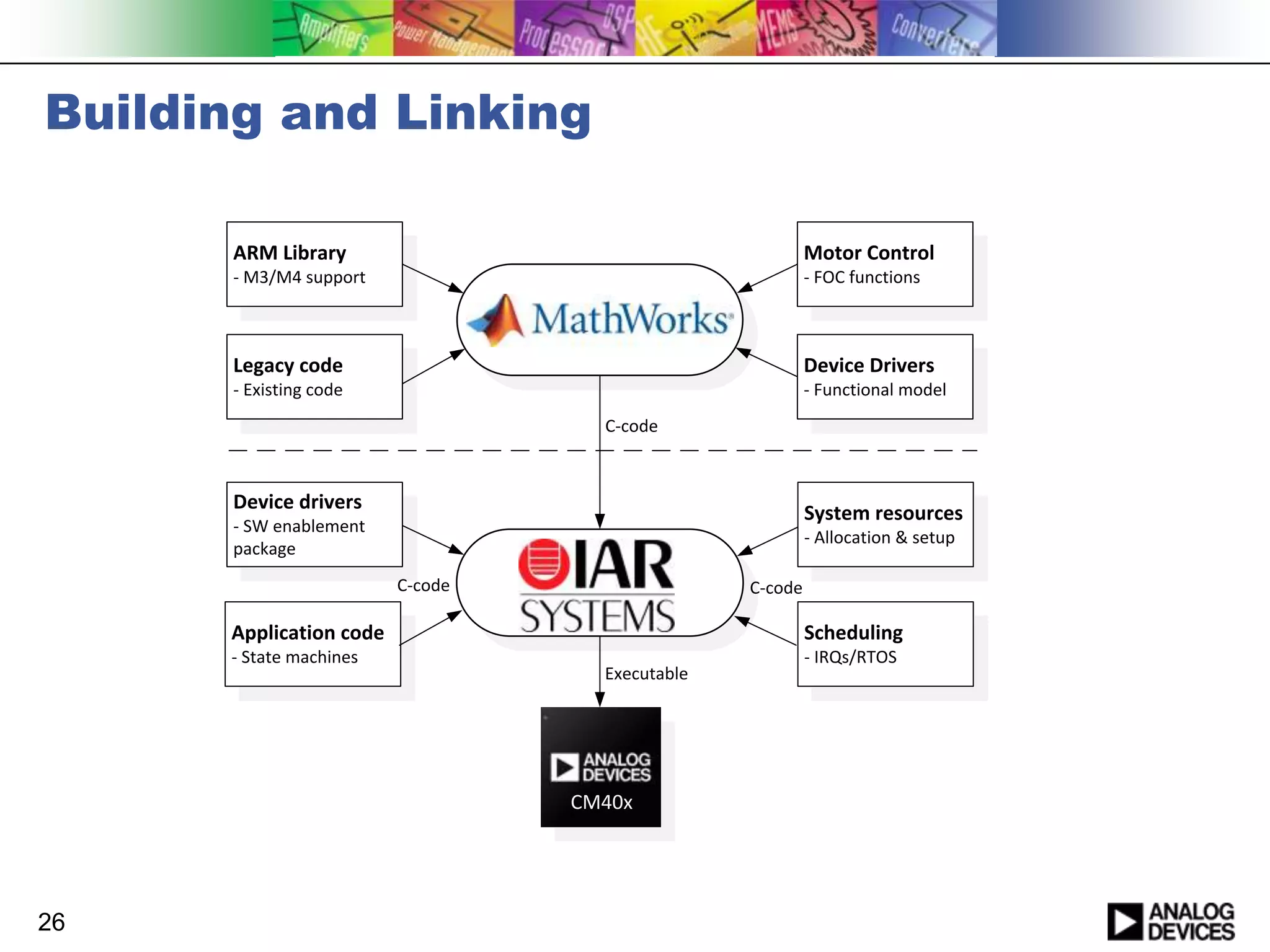
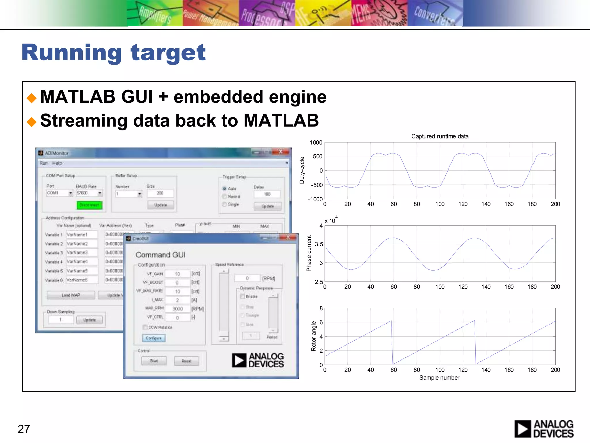
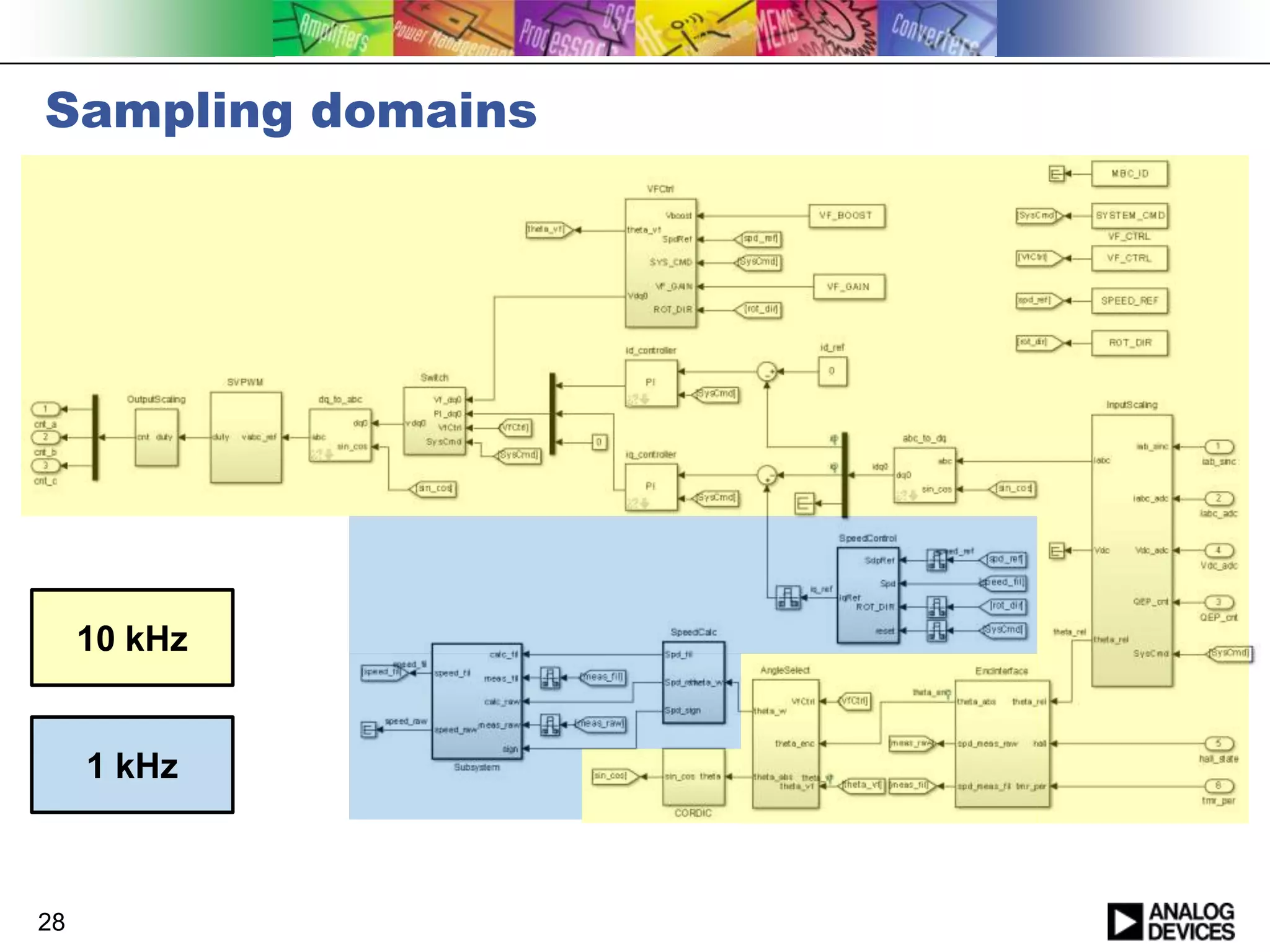
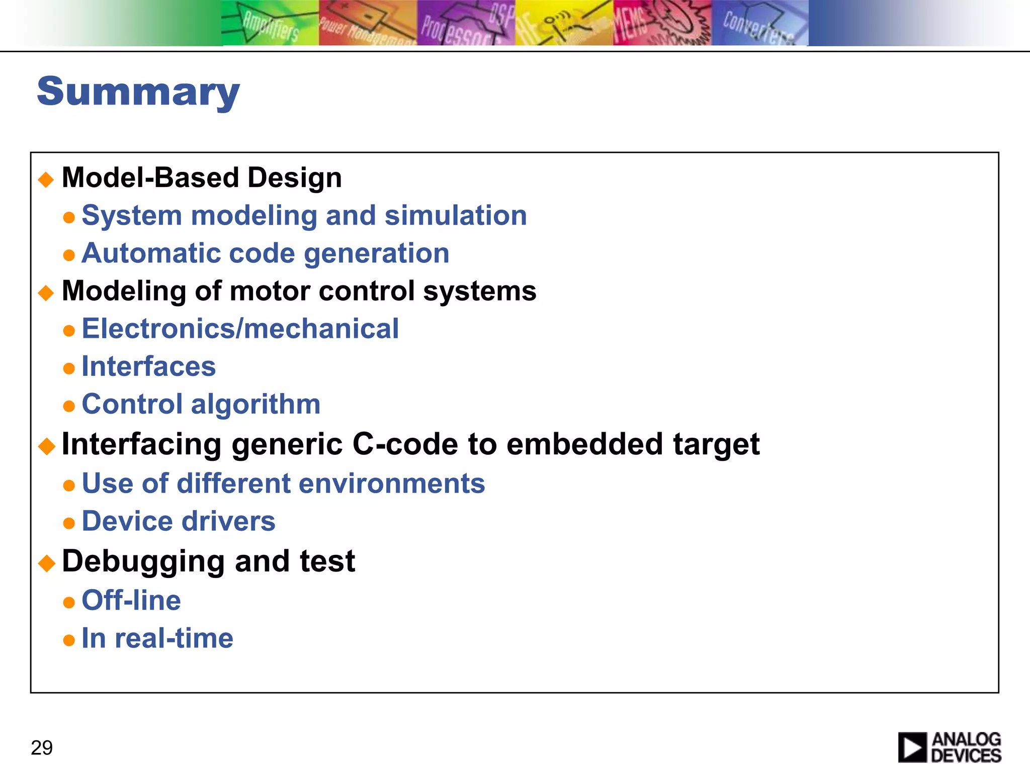


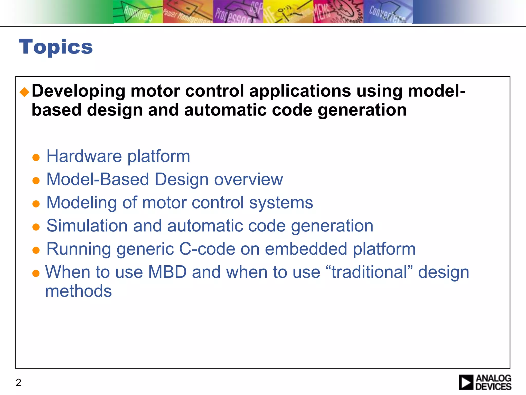
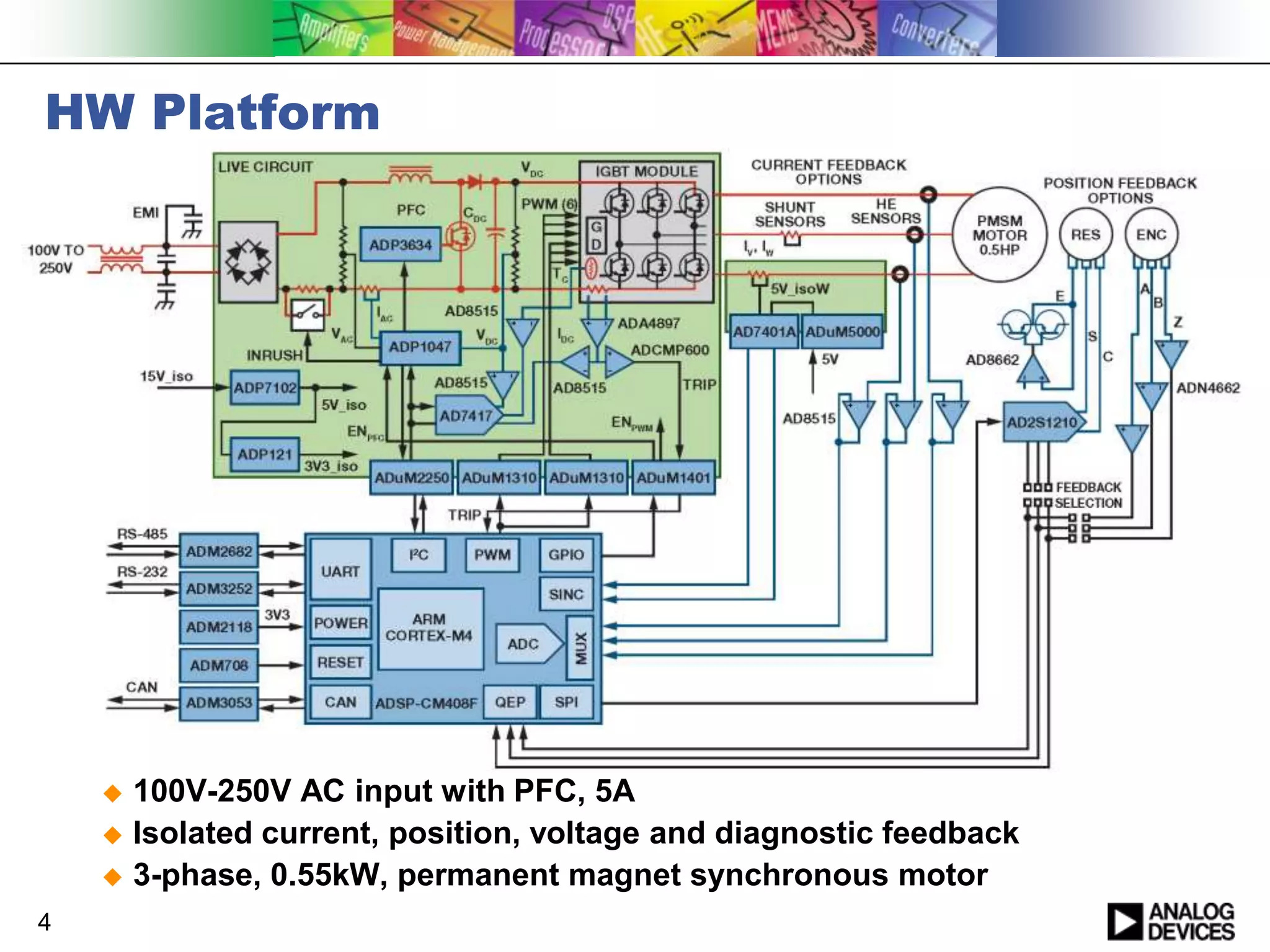
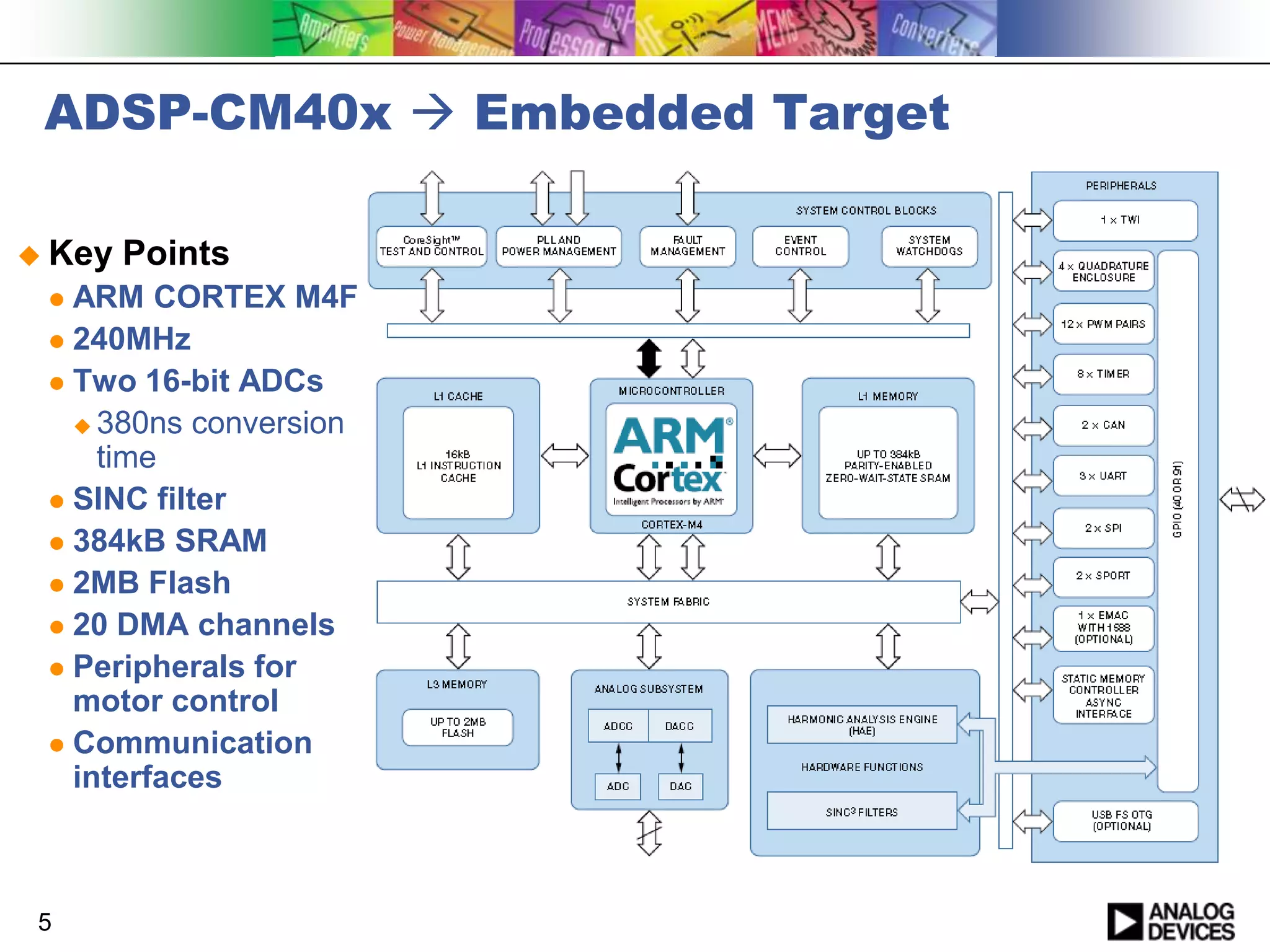
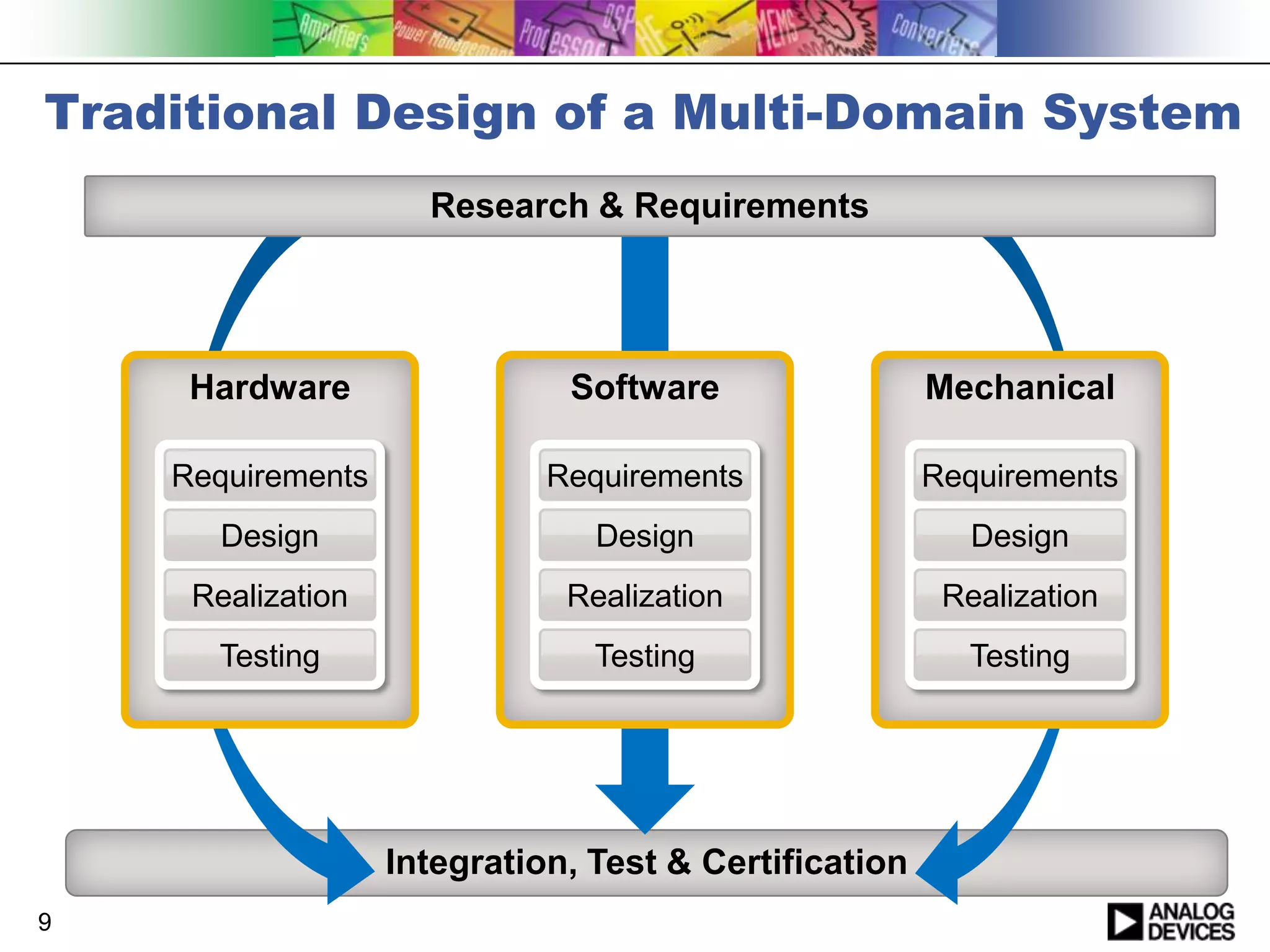
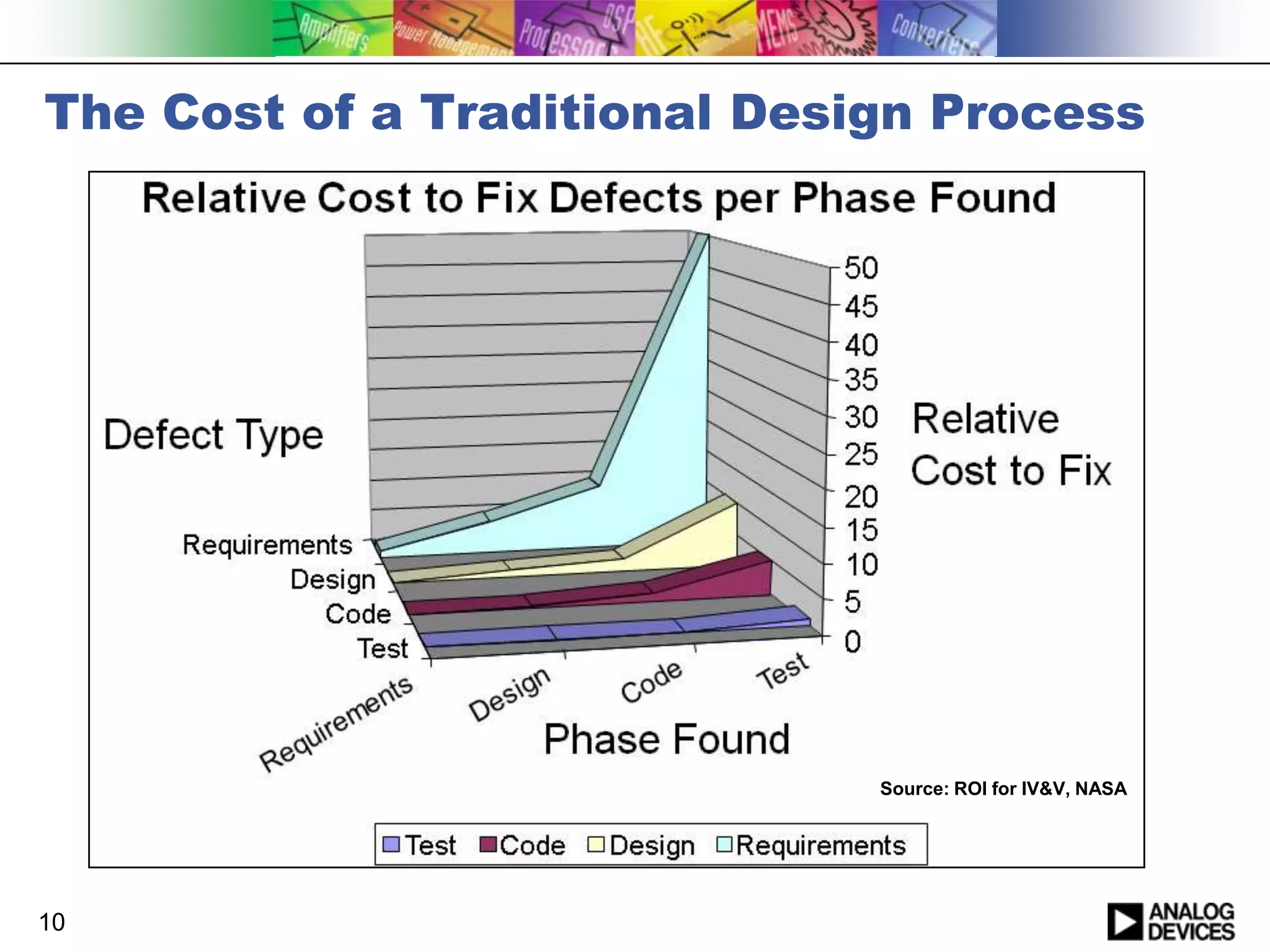
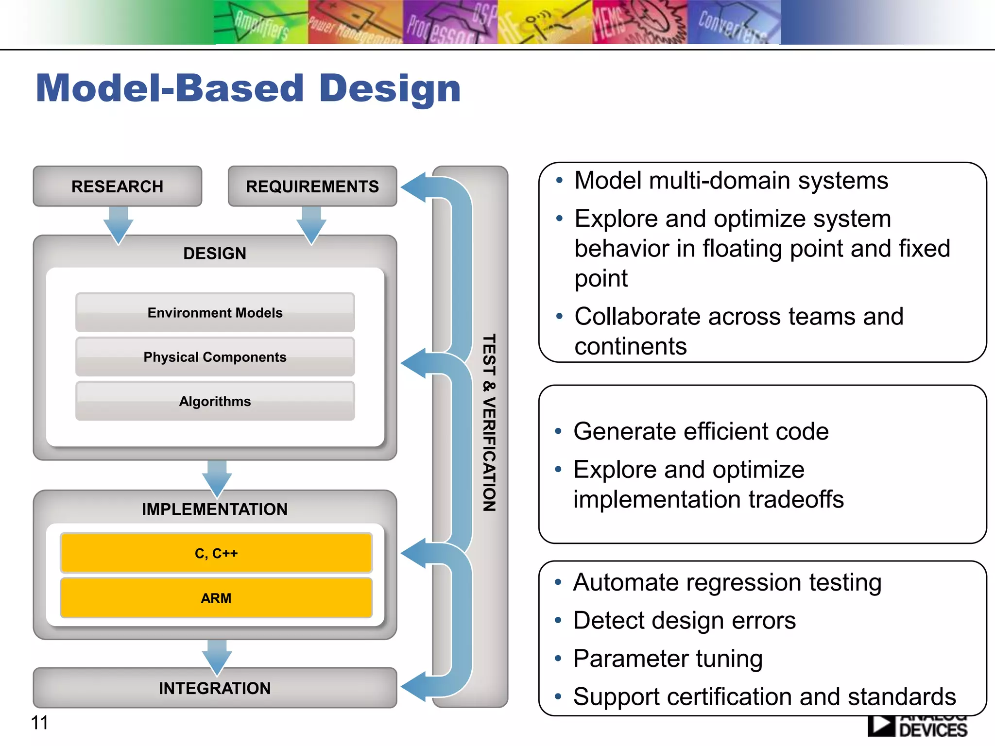
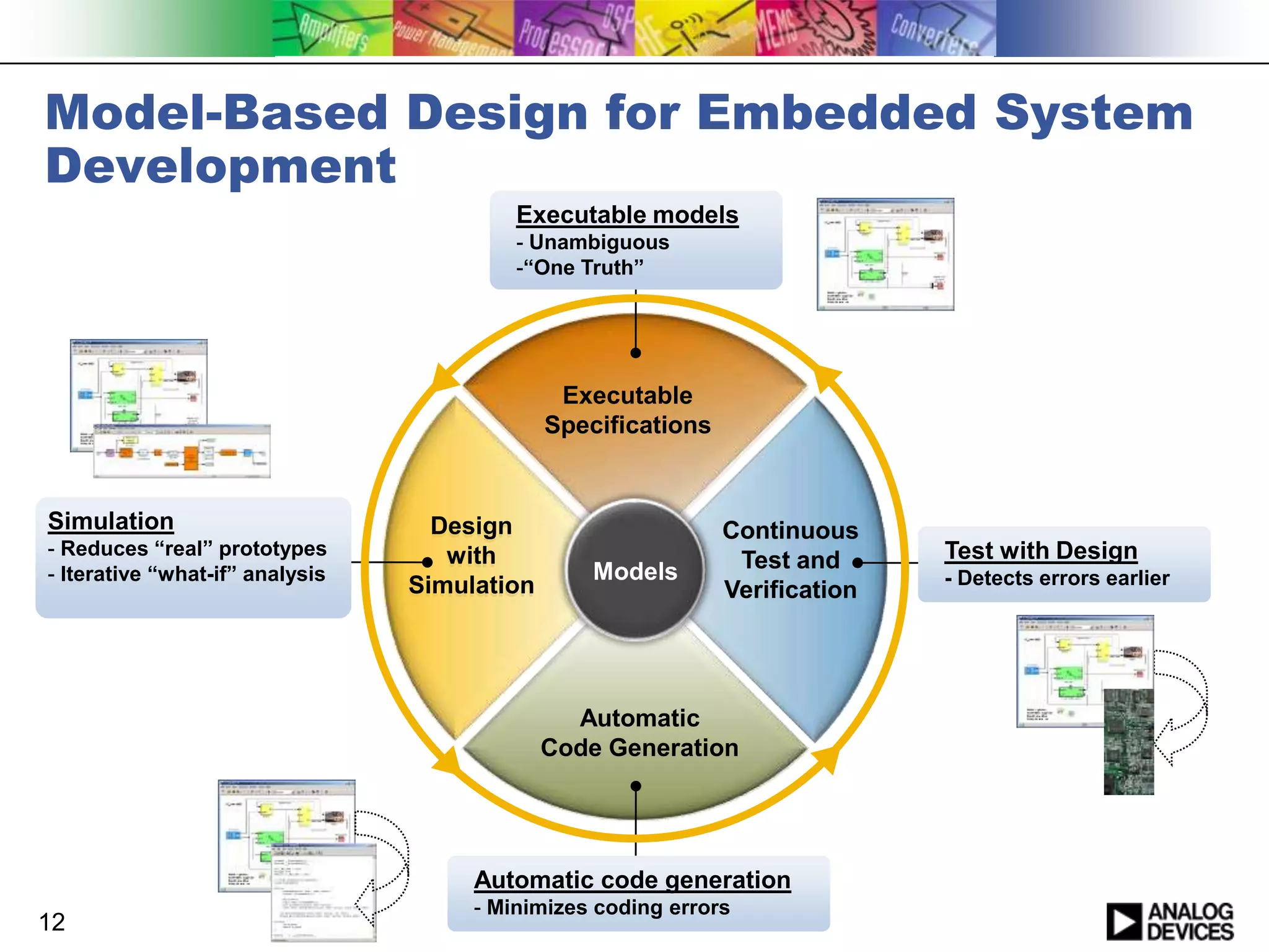
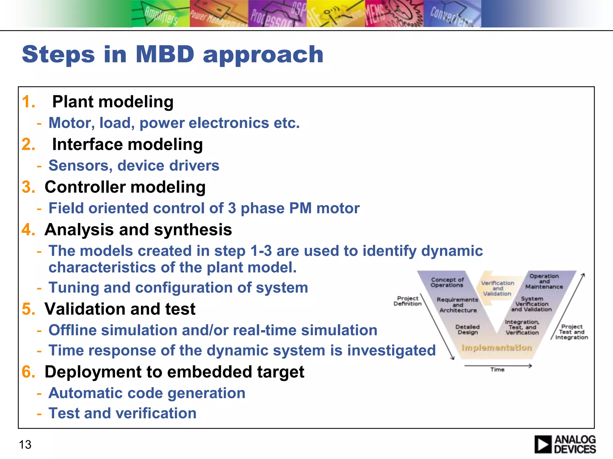
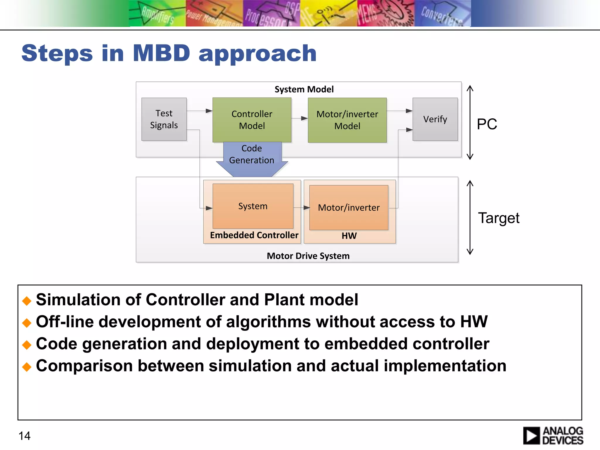
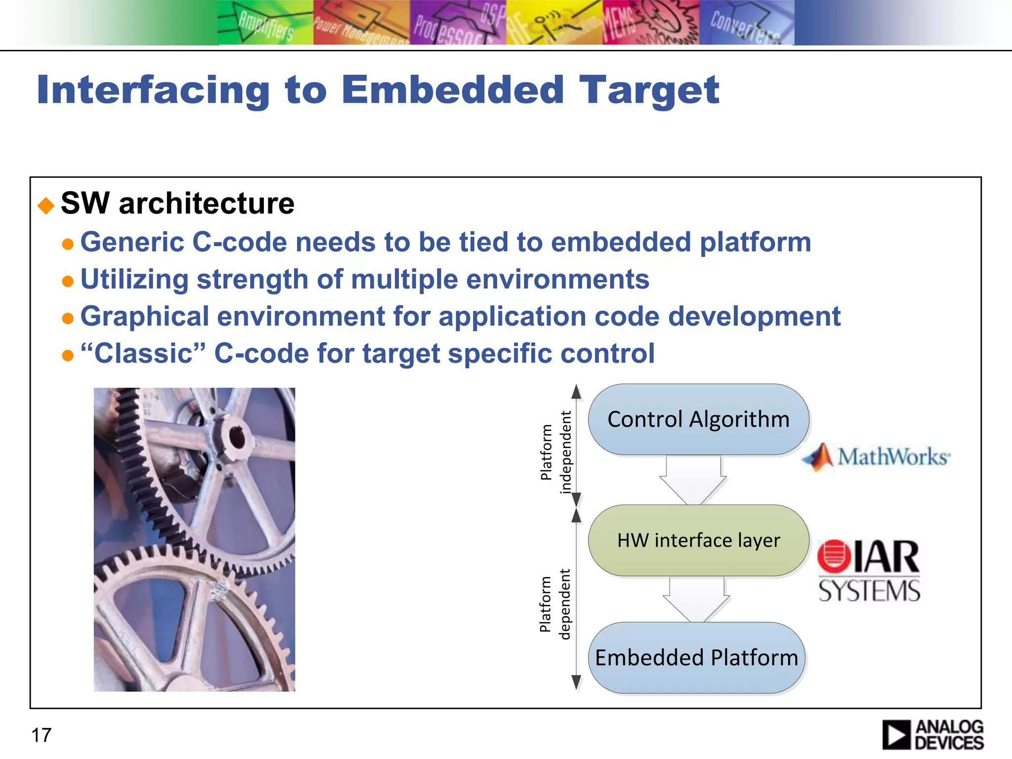
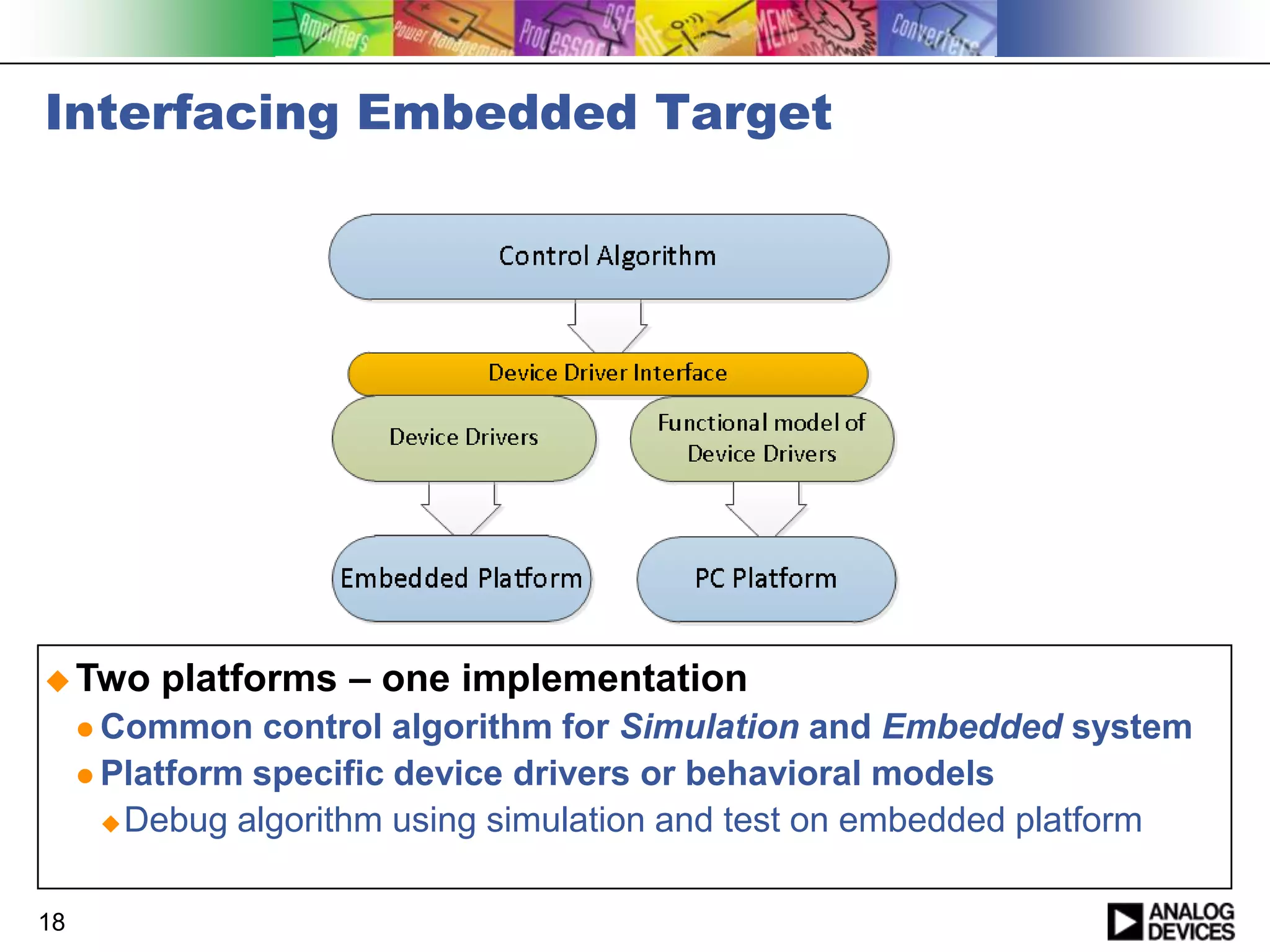
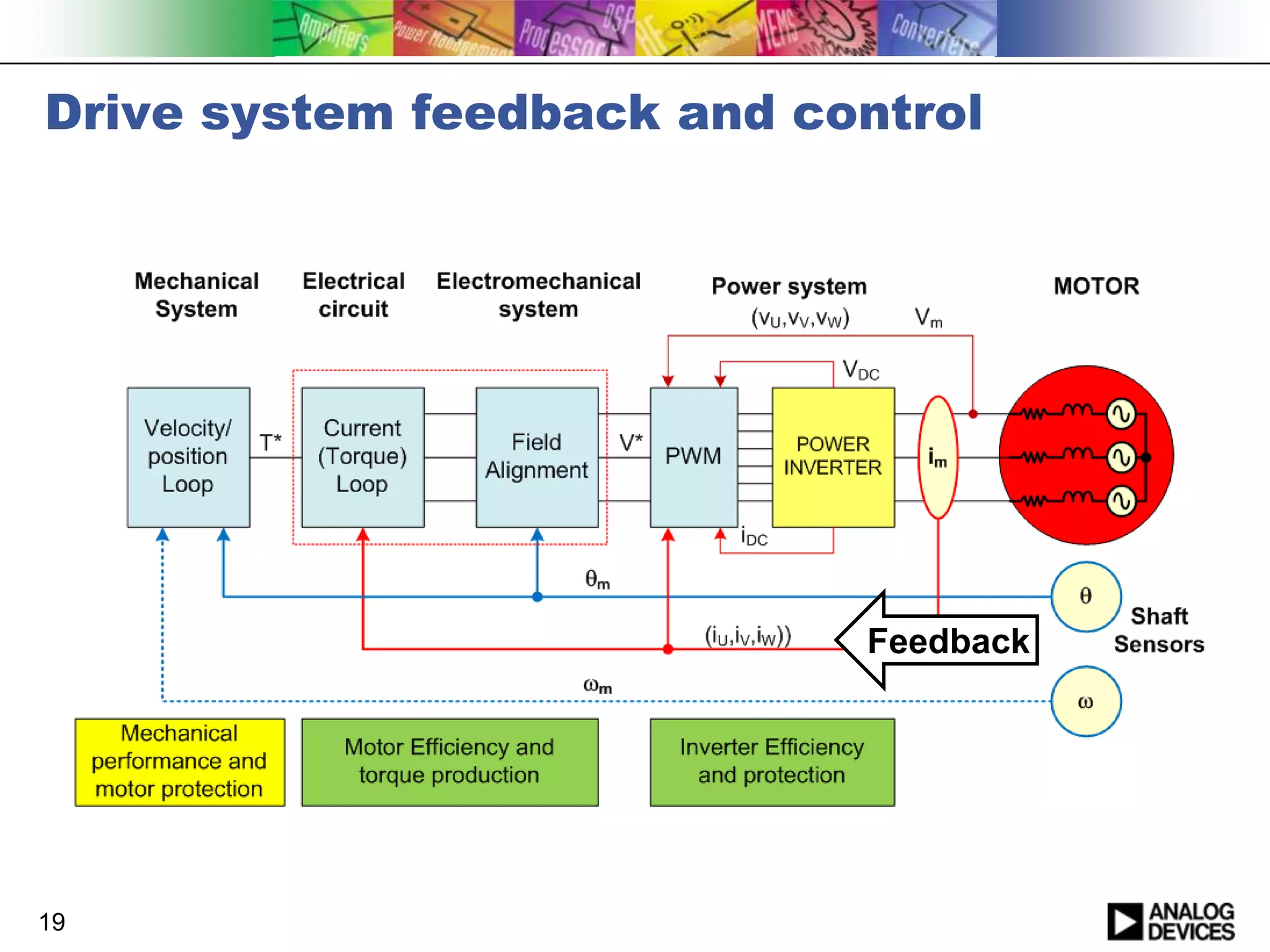
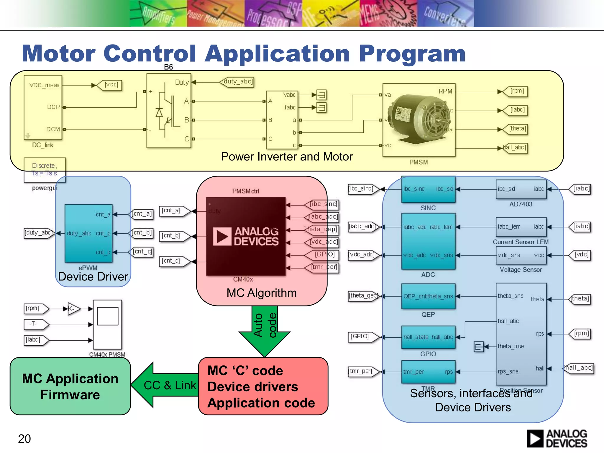
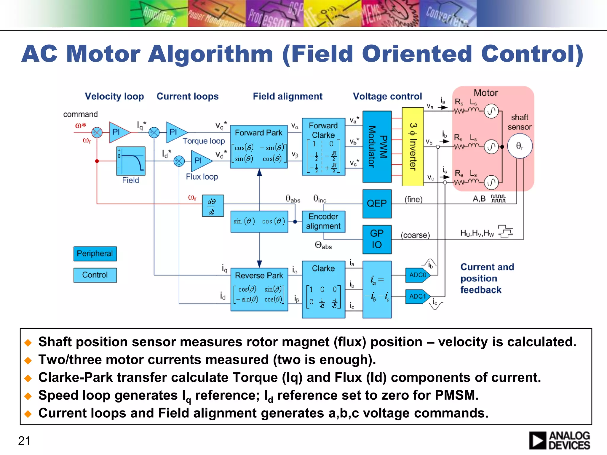
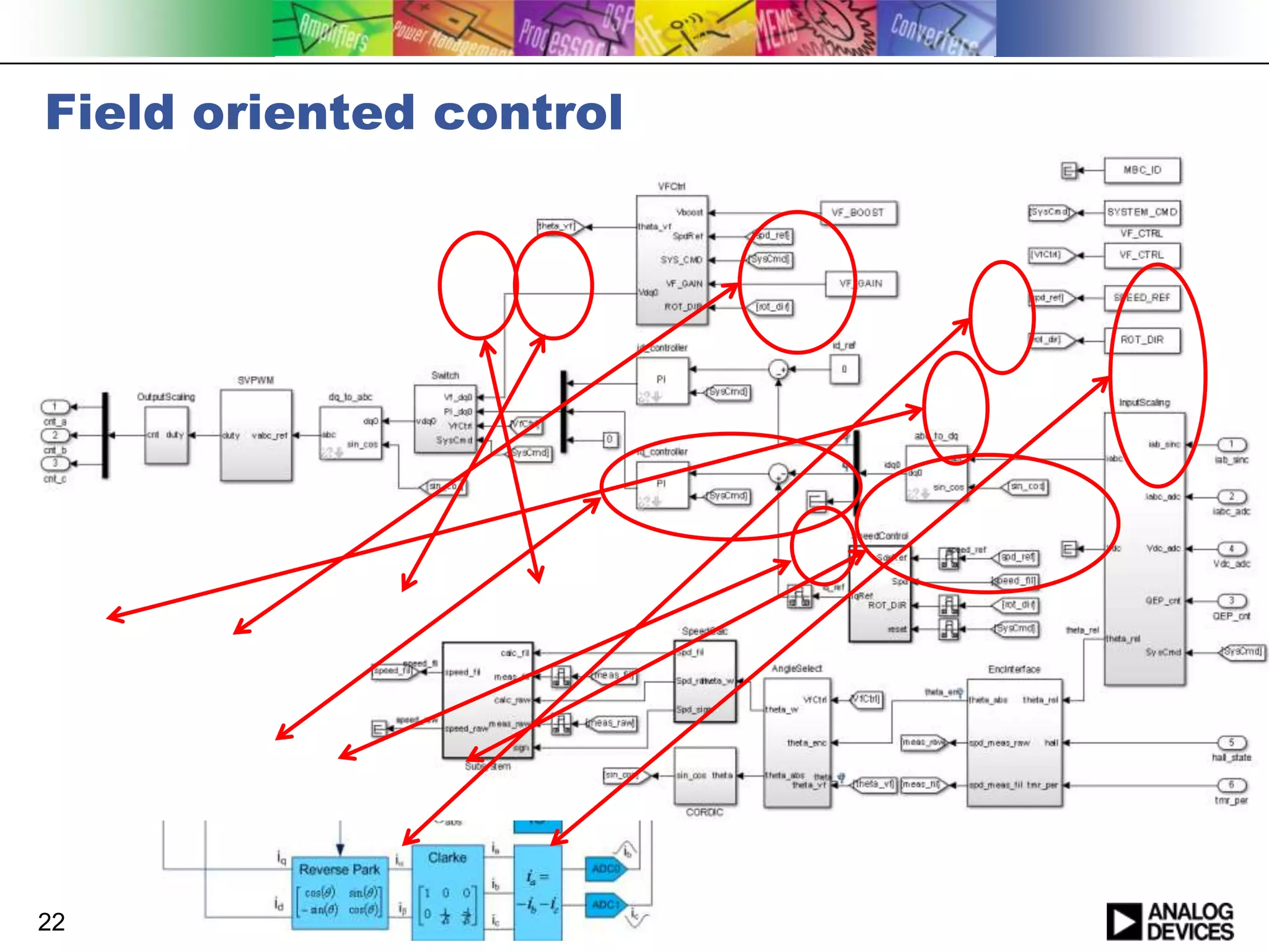
The document discusses model-based design for developing motor control applications. It describes modeling motor control systems using Simulink, simulating the models to analyze system behavior, and automatically generating C code to run on an embedded platform. Key aspects covered include modeling the motor, electronics, interfaces and control algorithm, generating generic C code, and interfacing this code to the embedded target using device drivers. The approach allows debugging the application through offline simulation and testing on the embedded hardware in real-time.