Downloaded 104 times


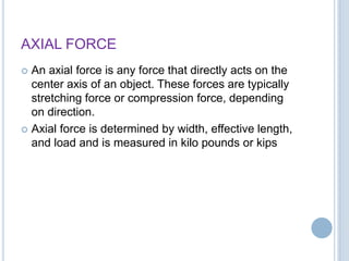
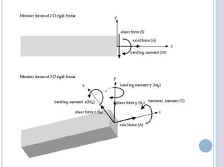
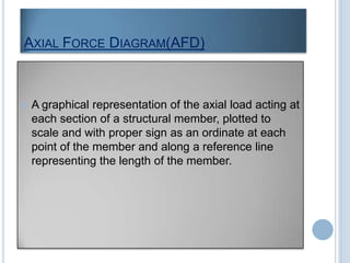
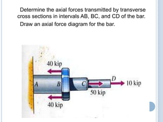
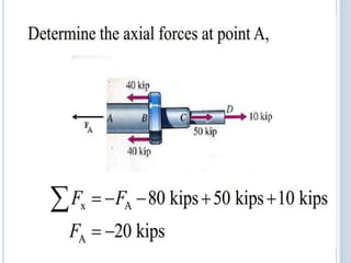
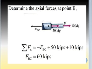
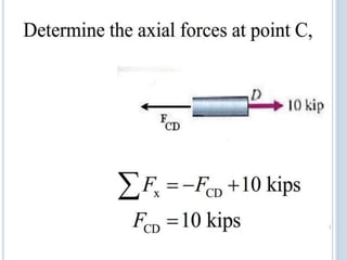
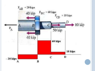
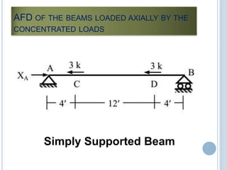
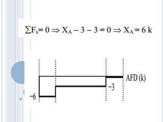
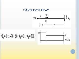
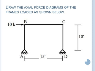
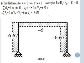
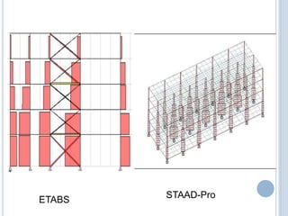


The document discusses axial force and axial force diagrams (AFDs). It defines axial force as any force that directly acts on the center axis of an object, typically stretching or compression forces. An AFD is a graphical representation of the axial loads acting at each section of a structural member, plotted proportionately with signs indicating tension or compression. The document provides examples of drawing AFDs for simply supported beams, cantilever beams, and frames under different loading conditions. It also lists some common structural analysis software that can be used to draw AFDs, such as ETABS, STAAD-Pro, and SAP-2000.