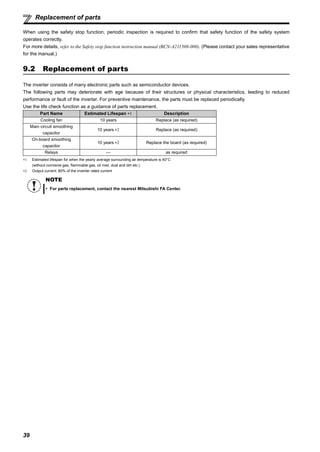
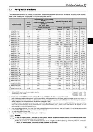
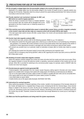
1. This document provides instructions for Mitsubishi inverter models FR-D700, FR-D720, FR-D740, FR-D720S, and FR-D710W.
2. It describes the parts of the inverter including the operation panel, terminals, and cooling fan. Precautions are provided around safety, installation, wiring, operation, and maintenance.
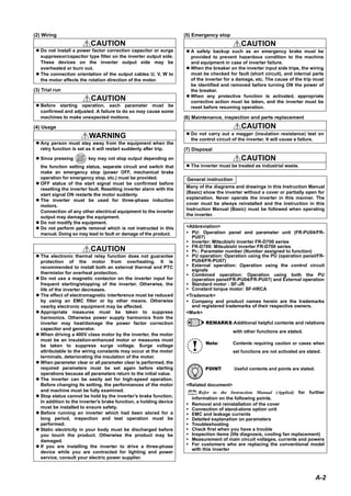
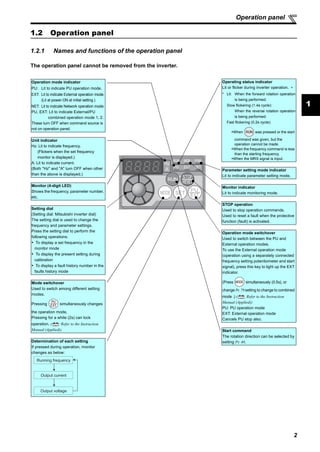
3. The operation panel is described which is used to monitor frequency, current, voltage and change settings using the mode switchover and setting dial. Safety instructions are categorized as Warning and Caution and cover electrical shock, fire, and injury prevention.
![FR-D700
INSTRUCTION MANUAL (BASIC)
FR-D720-0.1K to 15K
FR-D740-0.4K to 15K
FR-D720S-0.1K to 2.2K
FR-D710W-0.1K to 0.75K
INVERTER
700
4
5
6
7
8
9
3
2
1
10
CONTENTS
OUTLINE ...................................................................................1
INSTALLATION AND WIRING ...................................................5
PRECAUTIONS FOR USE OF THE INVERTER.........................18
FAILSAFE OF THE SYSTEM WHICH USES THE INVERTER ...20
DRIVE THE MOTOR.................................................................21
ENERGY SAVING OPERATION FOR FANS AND PUMPS ........29
PARAMETERS .........................................................................30
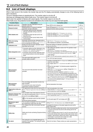
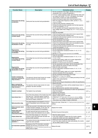
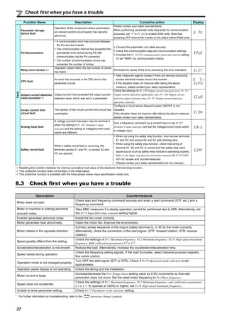
TROUBLESHOOTING ..............................................................34
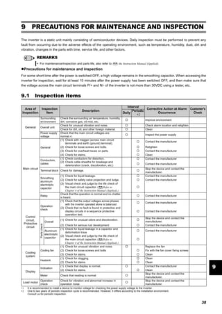
PRECAUTIONS FOR MAINTENANCE AND INSPECTION ........38
SPECIFICATIONS....................................................................40
Thank you for choosing this Mitsubishi Inverter.
This Instruction Manual (Basic) provides handling information and precautions for use of the equipment.
Please forward this Instruction Manual (Basic) to the end user.
To obtain the Instruction Manual (Applied) and the
Safety stop function instruction manual
Contact where you purchased the inverter, your Mitsubishi sales
representative, or the nearest Mitsubishi FA Center for the following
manuals:
Instruction Manual (Applied) [IB(NA)-0600366ENG]
Safety stop function instruction manual [BCN-A211508-000]
These manuals are required if you are going to utilize functions and
performance.
The PDF version of this manual is also available for download at
"MELFANS Web," the Mitsubishi Electric FA network service on the
world wide web (URL: http://www.MitsubishiElectric.co.jp/melfansweb)
1
2
3
4
5
6
7
8
9
10](https://image.slidesharecdn.com/hngdnsdngbintn-160313142933/85/H-ng-d-n-s-d-ng-bi-n-t-n-1-320.jpg)
![1
1 OUTLINE
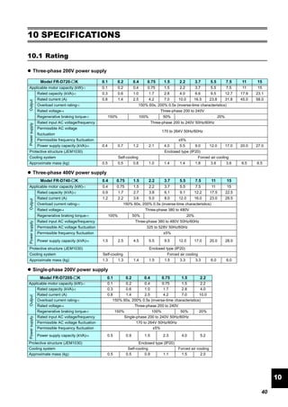
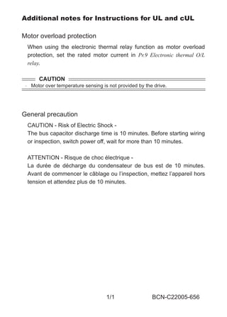
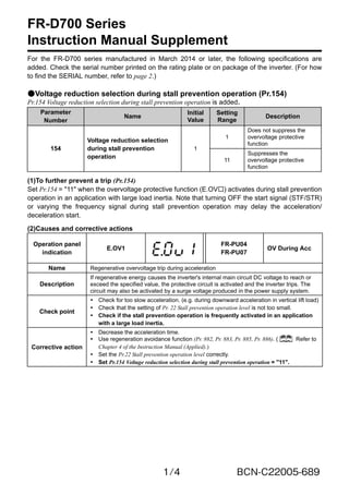
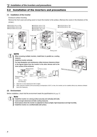
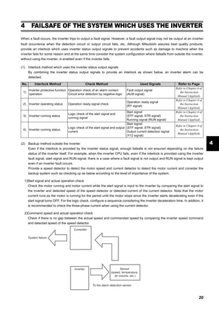
1.1 Product checking and parts identification
Unpack the inverter and check the capacity plate on the front cover and the rating plate on the inverter side face to ensure that
the product agrees with your order and the inverter is intact.
Inverter model
REMARKS
· For how to find the SERIAL number, refer to page 46.
Harmonic suppression guideline (when inverters are used in Japan)
All models of general-purpose inverters used by specific consumers are covered by "Harmonic Suppression Guidelines for Consumers
Who Receive High Voltage or Special High Voltage". (For further details, refer to Chapter 3 of the Instruction Manual (Applied).)
FR - -
Symbol Voltage class
D740 1.5
Represents the
inverter capacity [kW]
K
D720 Three-phase 200V class
D740 Three-phase 400V class
D720S Single-phase 200V class
D710W Single-phase 100V class
Capacity plate
Inverter model Serial number
1.5K
Rating plate
FR-D740-1.5KInverter model
Input rating
Output rating
Serial number
Production year and month
Control circuit terminal block
(Refer to page 9)
Control logic switchover jumper
connector
The jumper connector is in the sink
logic (SINK) when shipped from the
factory. Move the jumper connector
to change to the source logic
(SOURCE). Always fit the jumper
connector to the either position.
( Refer to the Instruction Manual
(Applied))
Combed shaped wiring cover
Refer to the Instruction Manual
(Applied) for installation/removal.
Main circuit terminal block
(Refer to page 9)
Front cover
Refer to the Instruction
Manual (Applied) for
installation/removal.
PU connector
(Refer to page 8)
Voltage/current input switch
(Refer to page 8)
Operation panel
(Refer to page 2)
Cooling fan
The cooling fan is removable.
• Accessory
· Fan cover fixing screws (M3 × 35mm)
These screws are necessary for compliance with the
EU Directive. (Refer to page 43)
Capacity Quantity
1.5K to 3.7K 1
5.5K to 15K 2](https://image.slidesharecdn.com/hngdnsdngbintn-160313142933/85/H-ng-d-n-s-d-ng-bi-n-t-n-4-320.jpg)
![3
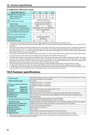
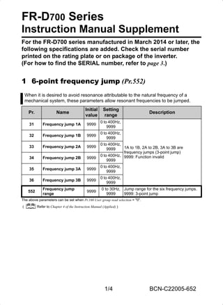
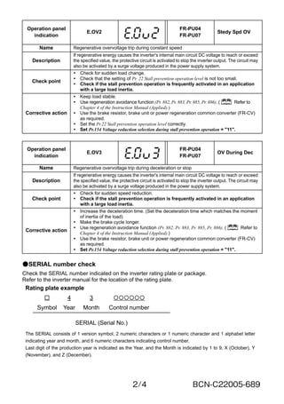
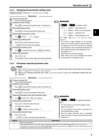
Operation panel
1.2.2 Basic operation (factory setting)
STOP
Operation mode switchover
ParametersettingFaultshistoryMonitor/frequencysetting
At power-ON (External operation mode)
PU operation mode
(output frequency monitor)
Parameter setting mode
PU Jog operation mode
Output current monitor Output voltage monitor
Display the
present setting
Value change
Value change
Parameter write is completed!!
Parameter and a setting value
flicker alternately.
Parameter clear All parameter
clear
Faults history clear
Initial value
change list
(Example)
(Example)
Frequency setting has been
written and completed!!
and frequency flicker alternately.
[Operation for displaying faults history]
The past eight faults can be displayed using the setting dial.
(The latest fault is ended by ".".)
When no fault history exists, is displayed.
While a fault is displayed:
The display shifts as follows by pressing : Output frequency at the fault
Output current Output voltage Energization time.
(After Energization time, it goes back to a fault display.)
Pressing the setting dial shows the fault history number.
(Refer to page 35)
operation_panel.fm 3 ページ 2012年4月23日 月曜日 午前11時46分](https://image.slidesharecdn.com/hngdnsdngbintn-160313142933/85/H-ng-d-n-s-d-ng-bi-n-t-n-6-320.jpg)
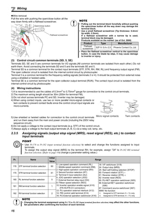
![12
Wiring
2
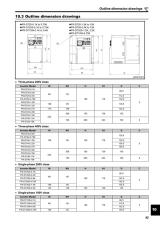
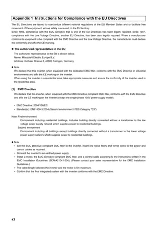
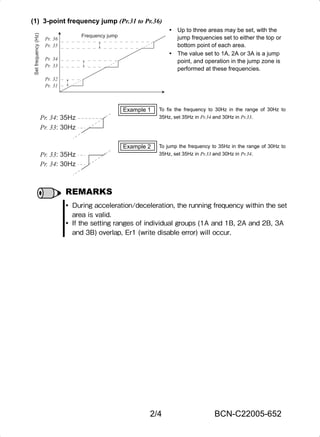
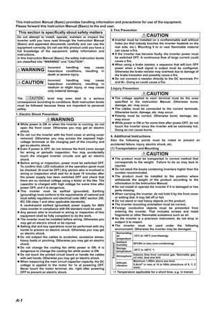
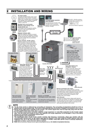
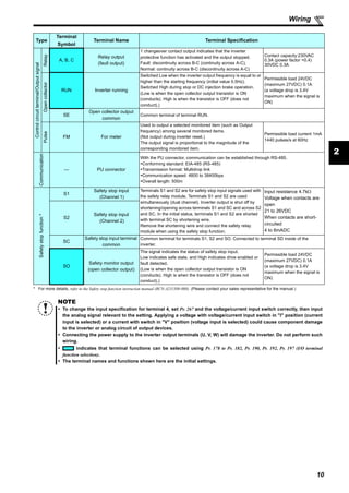
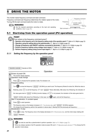
(1) Cable sizes etc., of the main control circuit terminals and earth (ground) terminals
Select the recommended cable size to ensure that a voltage drop will be 2% or less.
If the wiring distance is long between the inverter and motor, a main circuit cable voltage drop will cause the motor torque to
decrease especially at the output of a low frequency.
The following table indicates a selection example for the wiring length of 20m.
Three-phase 200V class (when input power supply is 220V)
Three-phase 400V class (when input power supply is 440V)
Single-phase 200V class (when input power supply is 220V)
Single-phase 100V class (when input power supply is 100V)
∗1 The cable size is that of the cable (HIV cable (600V class 2 vinyl-insulated cable) etc.) with continuous maximum permissible temperature of 75°C. Assumes
that the surrounding air temperature is 50°C or less and the wiring distance is 20m or less.
∗2 The recommended cable size is that of the cable (THHW cable) with continuous maximum permissible temperature of 75°C. Assumes that the surrounding
air temperature is 40°C or less and the wiring distance is 20m or less. (Selection example for use mainly in the United States.)
∗3 The recommended cable size is that of the cable (PVC cable) with continuous maximum permissible temperature of 70°C. Assumes that the surrounding air
temperature is 40°C or less and the wiring distance is 20m or less. (Selection example for use mainly in Europe.)
∗4 The terminal screw size indicates the terminal size for R/L1, S/L2, T/L3, U, V, W, PR, P/+, N/-, P1 and a screw for earthing (grounding).
Screw size for earthing (grounding) the FR-D720-15K is indicated in parentheses.
For single-phase power input, the terminal screw size indicates the size of terminal screw for R/L1, S/L2, U, V, W, PR, P/+, N/-, P1 and a screw for earthing
(grounding).
The line voltage drop can be calculated by the following formula:
Line voltage drop [V]=
Use a larger diameter cable when the wiring distance is long or when it is desired to decrease the voltage drop (torque
reduction) in the low speed range.
Applicable Inverter
Model
Terminal
Screw
Size ∗4
Tightening
Torque
N·m
Crimping
Terminal
Cable Size
HIV Cables, etc. (mm2
) ∗1 AWG ∗2 PVC Cables, etc. (mm2
) ∗3
R/L1
S/L2
T/L3
U, V, W
R/L1
S/L2
T/L3
U, V, W
Earthing
(grounding)
cable
R/L1
S/L2
T/L3
U, V, W
R/L1
S/L2
T/L3
U, V, W
Earthing
(grounding)
cable
FR-D720-0.1K to 0.75K M3.5 1.2 2-3.5 2-3.5 2 2 2 14 14 2.5 2.5 2.5
FR-D720-1.5K, 2.2K M4 1.5 2-4 2-4 2 2 2 14 14 2.5 2.5 2.5
FR-D720-3.7K M4 1.5 5.5-4 5.5-4 3.5 3.5 3.5 12 12 4 4 4
FR-D720-5.5K M5 2.5 5.5-5 5.5-5 5.5 5.5 5.5 10 10 6 6 6
FR-D720-7.5K M5 2.5 14-5 8-5 14 8 5.5 6 8 16 10 6
FR-D720-11K M5 2.5 14-5 14-5 14 14 14 6 6 16 16 16
FR-D720-15K M6 (M5) 4.4 22-6 22-6 22 22 14 4 4 25 25 16
Applicable Inverter
Model
Terminal
Screw
Size ∗4
Tightening
Torque
N·m
Crimping
Terminal
Cable Size
HIV Cables, etc. (mm2) ∗1 AWG ∗2 PVC Cables, etc. (mm2) ∗3
R/L1
S/L2
T/L3
U, V, W
R/L1
S/L2
T/L3
U, V, W
Earthing
(grounding)
cable
R/L1
S/L2
T/L3
U, V, W
R/L1
S/L2
T/L3
U, V, W
Earthing
(grounding)
cable
FR-D740-0.4K to 3.7K M4 1.5 2-4 2-4 2 2 2 14 14 2.5 2.5 2.5
FR-D740-5.5K M4 1.5 5.5-4 2-4 3.5 2 3.5 12 14 4 2.5 4
FR-D740-7.5K M4 1.5 5.5-4 5.5-4 3.5 3.5 3.5 12 12 4 4 4
FR-D740-11K M4 1.5 5.5-4 5.5-4 5.5 5.5 8 10 10 6 6 10
FR-D740-15K M5 2.5 8-5 8-5 8 8 8 8 8 10 10 10
Applicable Inverter
Model
Terminal
Screw
Size ∗4
Tightening
Torque
N·m
Crimping
Terminal
Cable Size
HIV Cables, etc. (mm2
) ∗1 AWG ∗2 PVC Cables, etc. (mm2
) ∗3
R/L1
S/L2
U, V, W
R/L1
S/L2
U, V, W
Earthing
(grounding)
cable
R/L1
S/L2
U, V, W
R/L1
S/L2
U, V, W
Earthing
(grounding)
cable
FR-D720S-0.1K to 0.75K M3.5 1.2 2-3.5 2-3.5 2 2 2 14 14 2.5 2.5 2.5
FR-D720S-1.5K M4 1.5 2-4 2-4 2 2 2 14 14 2.5 2.5 2.5
FR-D720S-2.2K M4 1.5 5.5-4 2-4 3.5 2 3.5 12 14 4 2.5 4
Applicable Inverter
Model
Terminal
Screw
Size ∗4
Tightening
Torque
N·m
Crimping
Terminal
Cable Size
HIV Cables, etc. (mm2) ∗1 AWG ∗2 PVC Cables, etc. (mm2) ∗3
R/L1
S/L2
U, V, W
R/L1
S/L2
U, V, W
Earthing
(grounding)
cable
R/L1
S/L2
U, V, W
R/L1
S/L2
U, V, W
Earthing
(grounding)
cable
FR-D710W-0.1K to 0.4K M3.5 1.2 2-3.5 2-3.5 2 2 2 14 14 2.5 2.5 2.5
FR-D710W-0.75K M4 1.5 5.5-4 2-4 3.5 2 2 12 14 4 2.5 2.5
NOTE
Tighten the terminal screw to the specified torque. A screw that has been tightened too loosely can cause a short circuit or
malfunction. A screw that has been tightened too tightly can cause a short circuit or malfunction due to the unit breakage.
Use crimping terminals with insulation sleeve to wire the power supply and motor.
3 × wire resistance[mΩ/m] × wiring distance[m] × current[A]
1000](https://image.slidesharecdn.com/hngdnsdngbintn-160313142933/85/H-ng-d-n-s-d-ng-bi-n-t-n-15-320.jpg)
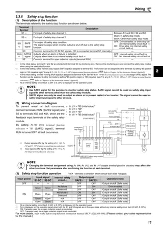
![23
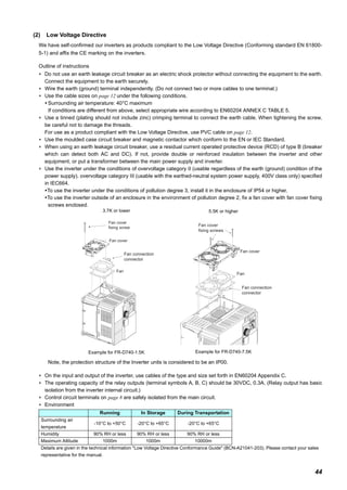
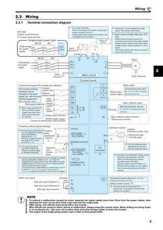
Start/stop from the operation panel (PU operation)
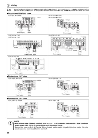
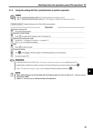
5.1.3 Setting the frequency by switches (three-speed setting) (Pr. 4 to Pr. 6)
POINT
Use the operation panel ( ) to give a start command.
Switch ON the RH, RM, or RL signal to give a frequency command.
Set "4" (External/PU combined operation mode 2) in Pr. 79 Operation mode selection.
[Connection diagram]
Operation example Operation at low speed (10Hz)
Operation
1.
Screen at power-ON
The monitor display appears.
2.
Easy operation mode setting
Press and for 0.5s. " " appears, and the [PRM] indicator flickers.
3.
Operation mode selection
Turn until " " appears. [PU] and [PRM] indicators flicker.
4.
Operation mode setting
Press to enter the setting. (Set "4" in Pr. 79.)
" " and " " flicker alternately. [PU] and [EXT] indicators are lit.
5.
Start
Turn ON the low-speed switch (RL).
6.
Acceleration constant speed
Press to start running.
The frequency value on the display increases in Pr. 7 Acceleration time, and " " (10.00Hz) appears.
[RUN] indicator is lit during forward rotation operation and flickers slowly during reverse rotation operation.
7.
Deceleration
Press to stop.
The frequency value on the display decreases in Pr. 8 Deceleration time, and the motor stops rotating with " " (0.00Hz)
displayed.
8.
Stop
Turn OFF the low-speed switch (RL).
REMARKS
The initial values of the terminals RH, RM, RL are 60Hz, 30Hz, and 10Hz. (Use Pr. 4, Pr. 5 and Pr. 6 to change.)
In the initial setting, when two or three of multi-speed settings are simultaneously selected, priority is given to the set frequency
of the lower signal.
For example, when the RH and RM signals turn ON, the RM signal (Pr. 5) has a higher priority.
Maximum of 15-speed operation can be performed. ( Refer to Chapter 4 of the Instruction Manual (Applied).)
SD
RH
RM
RL
Inverter
Operation
panel
High speed
Middle speed
Low speed
ON
ON
ON
Outputfrequency(Hz)
Speed 1
(High speed)
Speed 2
(Middle speed)
Speed 3
(Low speed)
RH
RM
RL
Time](https://image.slidesharecdn.com/hngdnsdngbintn-160313142933/85/H-ng-d-n-s-d-ng-bi-n-t-n-26-320.jpg)
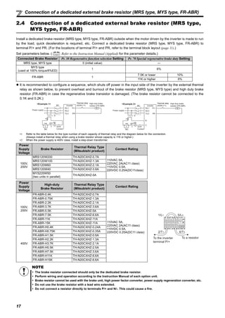
![24
Start/stop from the operation panel (PU operation)
5
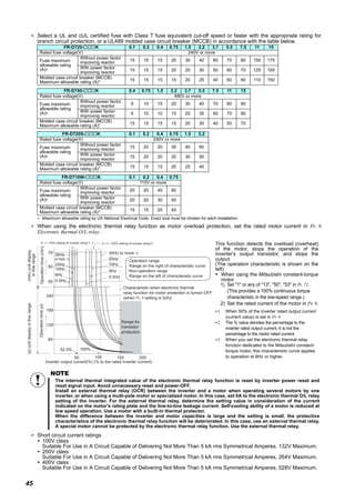
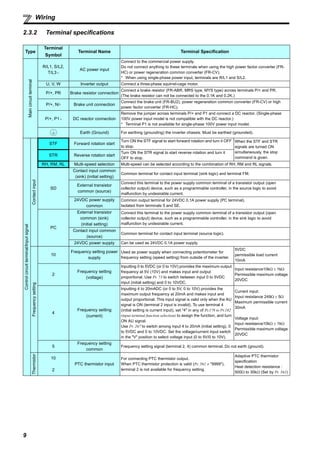
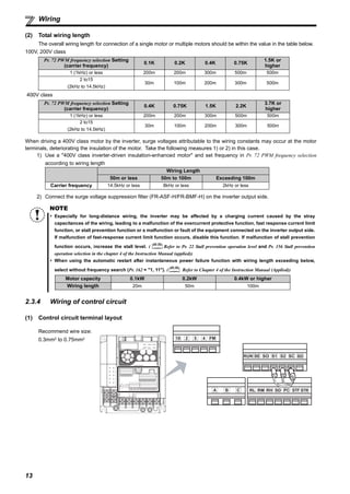
5.1.4 Setting the frequency by analog input (voltage input/current input)
POINT
Use the operation panel ( ) to give a start command.
Use the potentiometer (frequency setting potentiometer) (voltage input) or 4-to-20mA input (current input) to
give a frequency command.
Set "4" (External/PU combined operation mode 2) in Pr. 79 Operation mode selection.
[Connection example for voltage input] [Connection example for current input]
(The inverter supplies 5V power to the frequency setting
potentiometer. (terminal 10))
Assign the AU signal in one of Pr. 178 to Pr. 182.
Operation example Operate at 60Hz.
Operation
1.
Screen at power-ON
The monitor display appears.
2.
Assignment of the AU signal (current input) (Refer to the step 3 for voltage input.)
Set Pr. 160 to "0" to activate extended parameters.
To assign the AU signal, set "4" in one of Pr. 178 to Pr. 182. (Refer to page 4 to change the setting.)
Turn ON the AU signal.
3.
Easy operation mode setting
Press and for 0.5s. " " appears, and the [PRM] indicator flickers.
4.
Operation mode selection
Turn until " " appears. [PU] and [PRM] indicators flicker.
5.
Operation mode setting
Press to enter the setting. (Set "4" in Pr.79.)
" " and " " flicker alternately. [PU] and [EXT] indicators are lit.
6.
Start
Press . [RUN] flickers fast as no frequency command is given.
7.
Acceleration constant speed
For voltage input, turn the potentiometer (frequency setting potentiometer) clockwise slowly to full.
For current input, input 20mA.
The frequency value on the display increases in Pr. 7 Acceleration time, and " " (60.00Hz) appears.
[RUN] indicator is lit during forward rotation operation and flickers slowly during reverse rotation operation.
8.
Deceleration
For voltage input, turn the potentiometer (frequency setting potentiometer) counterclockwise slowly to full.
For current input, input 4mA.
The frequency value on the display decreases in Pr. 8 Deceleration time, and the motor stops rotating with " " (0.00Hz) displayed.
[RUN] flickers fast.
9.
Stop
Press . [RUN] indicator turns OFF.
REMARKS
For voltage input, the frequency (maximum potentiometer setting) at the full right turn of the (frequency setting) potentiometer is
60Hz in the initial setting. (To change the setting, use Pr. 125.) (Refer to page 28.)
For current input, the frequency at 20mA input is 60Hz in the initial setting. (To change the setting, use Pr. 126.) ( Refer to
Chapter 4 of the Instruction Manual (Applied.))
To input 10VDC to the terminal 2, set Pr. 73 Analog input selection = "0". The initial value is "1 (0 to 5V input)" ( Refer to
Chapter 4 of the Instruction Manual (Applied.)).
5
10
2
Frequency
setting
potentiometer
Inverter
Operation
panel
5(-)
4(+)
SD
Inverter
Operation
panelAU signal
Current signal
source
(4 to 20mADC)
AU signal
(terminal RH)](https://image.slidesharecdn.com/hngdnsdngbintn-160313142933/85/H-ng-d-n-s-d-ng-bi-n-t-n-27-320.jpg)
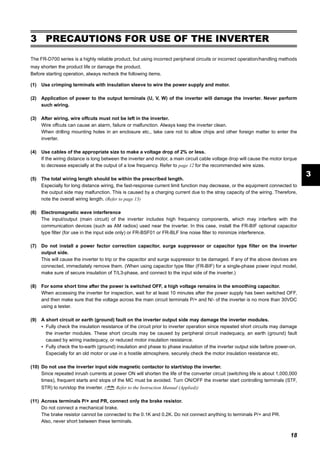
![25
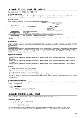
Start and stop using terminals (External operation)
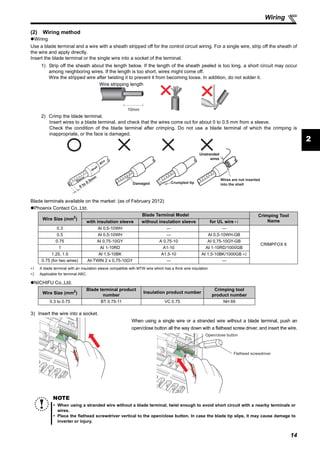
5.2 Start and stop using terminals (External operation)
5.2.1 Setting the frequency by the operation panel (Pr. 79 = 3)
POINT
From where is the frequency command given?
Operation at the frequency set in the frequency setting mode of the operation panel Refer to 5.2.1 (Refer to page 25)
Give a frequency command by switch (multi-speed setting) Refer to 5.2.2 (Refer to page 26)
Perform frequency setting by a voltage input signal Refer to 5.2.3 (Refer to page 27)
Perform frequency setting by a current input signal Refer to 5.2.3 (Refer to page 27)
POINT
Switch ON the STF(STR) signal to give a start command.
Use the operation panel ( ) to give a frequency command.
Set "3" (External/PU combined operation mode 1) in Pr. 79.
Operation example Operate at 30Hz.
Operation
1.
Screen at power-ON
The monitor display appears.
2.
Easy operation mode setting
Press and for 0.5s. " " appears, and the [PRM] indicator flickers.
3.
Operation mode selection
Turn until " " appears. [EXT] and [PRM] indicators flicker.
4.
Operation mode setting
Press to enter the setting. (Set "3" in Pr. 79.)
" " and " " flicker alternately. [PU] and [EXT] indicators are lit.
5.
Frequency setting
Turn to show the frequency " " you want to set. The frequency flickers for about 5s. While the value is flickering,
press to set the frequency. " " and " " flicker alternately. After about 3s of flickering, the indication of the value
goes back to " " (monitor display). (If is not pressed, the indication of the value goes back to " " (0.00Hz)
after about 5s of flickering. In that case, turn again, and set the frequency.)
6.
Start acceleration constant speed
Turn the start switch (STF or STR) ON.
The frequency value on the display increases in Pr. 7 Acceleration time, and " " (30.00Hz) appears.
[RUN] indicator is lit during forward rotation operation and flickers during reverse rotation operation.
(To change the set frequency, perform the operation in above step 5. Starting from the previously set frequency.)
7.
Deceleration stop
Turn OFF the start switch (STF or STR). The frequency value on the display decreases in Pr. 8 Deceleration time, and the motor
stops rotating with " " (0.00Hz) displayed. [RUN] turns OFF.
SD
STF
STR
Inverter
Operation
panelForward rotation start
Reverse rotation start
[Connection diagram]](https://image.slidesharecdn.com/hngdnsdngbintn-160313142933/85/H-ng-d-n-s-d-ng-bi-n-t-n-28-320.jpg)
![26
Start and stop using terminals (External operation)
5
5.2.2 Setting the frequency by switches (three-speed setting) (Pr. 4 to Pr. 6)
POINT
Switch ON the STF (STR) signal to give a start command.
Switch ON the RH, RM, or RL signal to give a frequency command.
Operation example Operation at high speed (60Hz)
Operation
1.
Screen at power-ON
The monitor display appears.
2.
Start
Turn ON the high-speed switch (RH).
3.
Acceleration constant speed
Turn ON the start switch (STF or STR). The frequency value on the display increases in Pr. 7 Acceleration time, and " "
(60.00Hz) appears.
[RUN] indicator is lit during forward rotation operation and flickers during reverse rotation operation.
When RM is turned ON, 30Hz is displayed. When RL is turned ON, 10Hz is displayed.
4.
Deceleration
Turn OFF the start switch (STF or STR). The frequency value on the display decreases in Pr. 8 Deceleration time, and the motor
stops rotating with " " (0.00Hz) displayed. [RUN] turns OFF.
5.
Stop
Turn OFF the high-speed switch (RH)
REMARKS
To always select the External operation mode, set Pr. 79 Operation mode selection = "2 (External operation mode)".
Initial values of terminals RH, RM, RL are 60Hz, 30Hz, and 10Hz. (To change, set Pr. 4, Pr. 5 and Pr. 6.)
In the initial setting, when two or three of multi-speed settings are simultaneously selected, priority is given to the set frequency
of the lower signal.
For example, when the RH and RM signals turn ON, the RM signal (Pr. 5) has a higher priority.
Maximum of 15-speed operation can be performed. ( Refer to Chapter 4 of the Instruction Manual (Applied).)
Inverter
Forward rotation start
Reverse rotation start
High speed
RM
STF
STR
RH
Middle speed
Low speed
SD
RL
[Connection diagram]
ON
ON
ON
Outputfrequency(Hz)
Speed 1
(High speed)
Speed 2
(Middle speed)
Speed 3
(Low speed)
RH
RM
RL
Time](https://image.slidesharecdn.com/hngdnsdngbintn-160313142933/85/H-ng-d-n-s-d-ng-bi-n-t-n-29-320.jpg)
![27
Start and stop using terminals (External operation)
5.2.3 Setting the frequency by analog input (voltage input/current input)
POINT
Switch ON the STF(STR) signal to give a start command.
Use the potentiometer (frequency setting potentiometer) (voltage input) or 4-to-20mA input (current input) to
give a frequency command.
[Connection example for voltage input] [Connection example for current input]
(The inverter supplies 5V power to the frequency setting
potentiometer. (terminal 10))
Assign the AU signal in one of Pr. 178 to Pr. 182.
Operation example Operate at 60Hz.
Operation
1.
Screen at power-ON
The monitor display appears.
2.
Assignment of the AU signal (current input) (Refer to the step 3 for voltage input.)
Set Pr. 160 to "0" to activate extended parameters.
To assign the AU signal, set "4" in one of Pr. 178 to Pr. 182. (Refer to page 4 to change the setting.)
Turn ON the AU signal.
3.
Start
Turn the start switch (STF or STR) ON.
[RUN] flickers fast because the frequency command is not given.
4.
Acceleration constant speed
For voltage input, turn the potentiometer (frequency setting potentiometer) clockwise slowly to full.
For current input, input 20mA.
The frequency value on the display increases in Pr. 7 Acceleration time, and " " (60.00Hz) appears.
[RUN] indicator is lit during forward rotation operation and flickers slowly during reverse rotation operation.
5.
Deceleration
For voltage input, turn the potentiometer (frequency setting potentiometer) counterclockwise slowly to full.
For current input, input 4mA.
The frequency value on the display decreases in Pr. 8 Deceleration time, and the motor stops rotating with " " (0.00Hz)
displayed.
[RUN] flickers fast.
6.
Stop
Turn the start switch (STF or STR) OFF.
[RUN] turns OFF.
REMARKS
To always select the External operation mode, set Pr. 79 Operation mode selection = "2 (External operation mode)".
For voltage input, the frequency (maximum potentiometer setting) at the full right turn of the (frequency setting) potentiometer is
60Hz in the initial setting. (To change the setting, use Pr.125.) (Refer to page 28.)
For current input, the frequency at 20mA input is 60Hz in the initial setting. (To change the setting, use Pr. 126.) ( Refer to
Chapter 4 of the Instruction Manual (Applied.))
To input 10VDC to the terminal 2, set Pr.73 Analog input selection = "0". The initial value is "1 (0 to 5V input)".
( Refer to Chapter 4 of the Instruction Manual (Applied).)
Frequency setting
potentiometer
Inverter
5
10
2
Forward rotation start
Reverse rotation start
STF
STR
SD
Inverter
5(-)
4(+)
SD
AU signal (terminal RH)AU signal
Forward rotation start
Reverse rotation start
STF
STR
Current signal
source
(4 to 20mADC)](https://image.slidesharecdn.com/hngdnsdngbintn-160313142933/85/H-ng-d-n-s-d-ng-bi-n-t-n-30-320.jpg)
![28
Start and stop using terminals (External operation)
5
5.2.4 Operating at 60Hz or higher using the external potentiometer
< How to change the maximum frequency>
Changing
example
When you want to use 0 to 5VDC input frequency setting potentiometer to change the frequency at 5V from 60Hz (initial value)
to 70Hz, make adjustment to output "70Hz" at 5V voltage input. Set "70Hz" in Pr. 125.
Operation
1.
Parameter selection
Turn until " " (Pr. 125) appears.
Press to show the present set value " " (60.00Hz).
2.
Changing the maximum frequency
Turn to change the set value to " "(70.00Hz).
Press to enter. " " and " " flicker alternately.
3.
Mode/monitor check
Press twice to choose the monitor/frequency monitor.
4.
Start
Turn the start switch (STF or STR) ON.
[RUN] flickers fast because the frequency command is not given.
5.
Acceleration constant speed
Turn the potentiometer (frequency setting potentiometer) clockwise slowly to full.
The frequency value on the display increases in Pr. 7 Acceleration time, and " " (70.00Hz) appears.
[RUN] indicator is lit during forward rotation operation and flickers slowly during reverse rotation operation.
6.
Deceleration
Turn the potentiometer (frequency setting potentiometer) counterclockwise slowly to full.
The frequency value on the display decreases in Pr. 8 Deceleration time, and the motor stops rotating with " " (0.00Hz)
displayed.
[RUN] flickers fast.
7.
Stop
Turn the start switch (STF or STR) OFF.
[RUN] turns OFF.
REMARKS
To change the value to 120Hz or more, the maximum frequency must be set to 120Hz or more.
Use calibration parameter C2 to set frequency at 0V and
calibration parameter C0 to adjust the meter.
( Refer to Chapter 4 of the Instruction Manual (Applied)).
To input 10VDC to the terminal 2, set Pr.73 Analog input
selection = "0". The initial value is "1 (0 to 5V input)".
( Refer to Chapter 4 of the Instruction Manual (Applied).)
As other adjustment methods of frequency setting voltage gain, there are methods to adjust with a voltage applied to across
terminals 2-5 and a method to adjust at any point without a voltage applied. ( Refer to Chapter 4 of the Instruction Manual
(Applied) for the setting method of calibration parameter C4.)
Change the frequency (60Hz) at the maximum current input (20mA in the initial setting)
Adjust it with Pr.126 Terminal 4 frequency setting gain frequency. ( Refer to Chapter 4 of the Instruction Manual (Applied).)
Change the frequency (0Hz) at the minimum current input (4mA in the initial setting)
Adjust with the calibration parameter C5 Terminal 4 frequency setting bias frequency. ( Refer to Chapter 4 of the Instruction
Manual (Applied).)
Initial value
Bias
C2 (Pr. 902)
0
0
Frequency
setting signal
100%
10V
0 5V
C3 (Pr. 902) C4 (Pr. 903)
Gain
Pr. 125
Output
frequency
(Hz)
60Hz](https://image.slidesharecdn.com/hngdnsdngbintn-160313142933/85/H-ng-d-n-s-d-ng-bi-n-t-n-31-320.jpg)
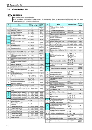
![30
Simple mode parameters
7
7 PARAMETERS
Simple variable-speed operation can be performed with the inverter in the initial settings. Set the required parameters
according to the load and operating conditions. Use the operation panel to set or change a parameter. (Refer to Chapter 4
of the Instruction Manual (Applied) for the detailed description of parameters.
7.1 Simple mode parameters
POINT
In the initial setting, only the simple mode parameters are displayed by the Pr.160 Extended function display selection
setting. Change the Pr.160 Extended function display selection setting as required. (Refer to page 57 to change the
parameter.
Parameter
Number
Name Unit
Initial
Value
Range Application
0 Torque boost 0.1%
6%/4%/3%/
2%*
0 to 30%
Use this parameter to increase starting torque under V/F
control. Use this when a loaded motor cannot be driven
and the warning [OL] occurs, then the inverter trips with
[OC1] under V/F control.
∗ Initial value depends on the inverter capacity.
(0.75K or lower/1.5K to 3.7K/5.5K, 7.5K/11K, 15K)
1 Maximum frequency 0.01Hz 120Hz 0 to 120Hz
Use this parameter to set the upper limit for the output
frequency.
2 Minimum frequency 0.01Hz 0Hz 0 to 120Hz
Use this parameter to set the lower limit for the output
frequency.
3 Base frequency 0.01Hz 60Hz 0 to 400Hz
Use this parameter when the rated motor frequency is 50Hz.
Check the rating plate of the motor.
4 Multi-speed setting (high speed) 0.01Hz 60Hz 0 to 400Hz
Use these parameters to change among pre-set operation
speeds with the terminals. The speeds are pre-set with
parameters.
5
Multi-speed setting (middle
speed)
0.01Hz 30Hz 0 to 400Hz
6 Multi-speed setting (low speed) 0.01Hz 10Hz 0 to 400Hz
7 Acceleration time 0.1s 5s/10s/15s* 0 to 3600s Use these parameters to set the acceleration/deceleration
time.
∗ Initial value depends on the inverter capacity.
(3.7K or lower/5.5K, 7.5K/11K, 15K)
8 Deceleration time 0.1s 5s/10s/15s* 0 to 3600s
9 Electronic thermal O/L relay 0.01A
Rated
inverter
current
0 to 500A
With this parameter, the inverter protects the motor from
heat.
Set the rated motor current.
79 Operation mode selection 1 0
0 External/PU switchover mode
1 Fixed to PU operation mode
2 Fixed to External operation mode
3
External/PU combined operation mode 1
(Start command from External, frequency command from
PU)
4
External/PU combined operation mode 2
(Frequency command from External, start command from
PU)
6 Switchover mode
7 External operation mode (PU operation interlock)
125
Terminal 2 frequency setting
gain frequency
0.01Hz 60Hz 0 to 400Hz
Use this parameter to change the frequency at the
maximum potentiometer setting (5V in the initial setting)
126
Terminal 4 frequency setting
gain frequency
0.01Hz 60Hz 0 to 400Hz
Use this parameter to change the frequency at the
maximum current input (20mA in the initial setting)
160
Extended function display
selection
1 9999
0 Simple mode + extended mode parameters are displayed.
9999 Only the simple mode parameters are displayed.
Pr.CL Parameter clear 1 0 0, 1
Setting "1" returns all parameters except calibration
parameters to the initial values.
ALLC All parameter clear 1 0 0, 1 Setting "1" returns all parameters to the initial values.
Er.CL Fault history clear 1 0 0, 1 Setting "1" clears eight past faults.
Pr.CH Initial value change list ⎯ ⎯ ⎯
Displays and sets the parameters changed from the initial
value.
6](https://image.slidesharecdn.com/hngdnsdngbintn-160313142933/85/H-ng-d-n-s-d-ng-bi-n-t-n-33-320.jpg)