Downloaded 29 times
![FR-E700
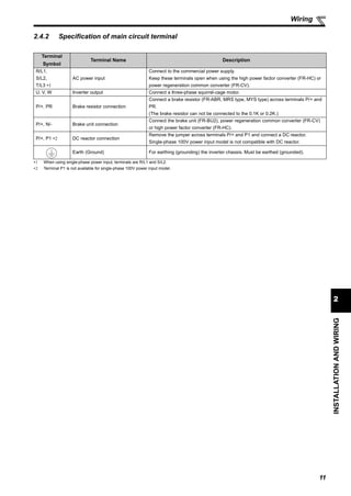
INSTRUCTION MANUAL (BASIC)
FR-E720-0.1K(SC) to 15K(SC)
FR-E740-0.4K(SC) to 15K(SC)
FR-E720S-0.1K(SC) to 2.2K(SC)
FR-E710W-0.1K to 0.75K
INVERTER
IB(NA)-0600276ENG-F(0906)MEE Printed in Japan Specifications subject to change without notice.
FR-E700INVERTERINSTRUCTIONMANUAL(BASIC)
F
700HEAD OFFICE: TOKYO BUILDING 2-7-3, MARUNOUCHI, CHIYODA-KU, TOKYO 100-8310, JAPAN
1
2
3
4
5
6
MODEL
MODEL
CODE
1A2-P25
FR-E700
INSTRUCTION MANUAL (BASIC)
CONTENTS
PRODUCT CHECKING AND PARTS IDENTIFICATION ............................. 1
INSTALLATION AND WIRING ..................................................................... 2
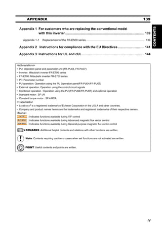
2.1 Peripheral devices..................................................................................................... 3
2.2 Removal and reinstallation of the cover.................................................................... 4
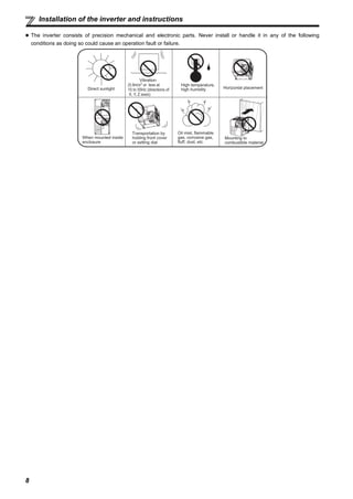
2.3 Installation of the inverter and instructions ............................................................... 7
2.4 Wiring ........................................................................................................................ 9
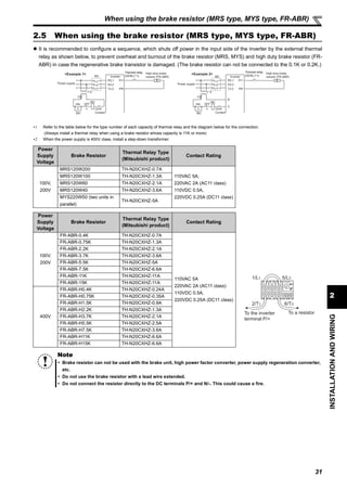
2.5 When using the brake resistor (MRS type, MYS type, FR-ABR) ........................... 31
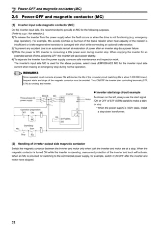
2.6 Power-OFF and magnetic contactor (MC).............................................................. 32
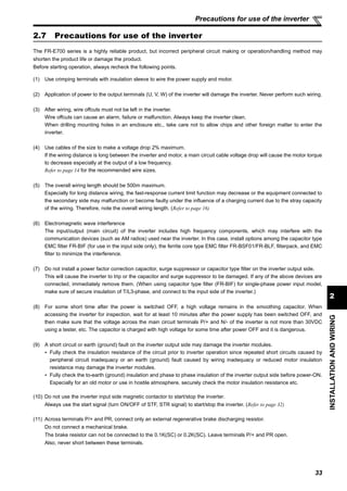
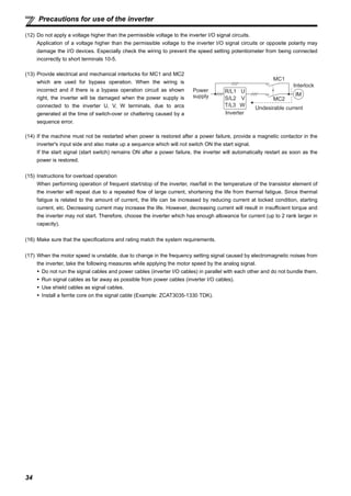
2.7 Precautions for use of the inverter.......................................................................... 33
2.8 Failsafe of the system which uses the inverter....................................................... 35
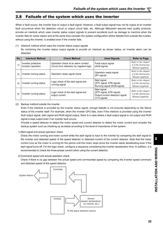
DRIVE THE MOTOR ................................................................................... 36
3.1 Step of operation..................................................................................................... 36
3.2 Operation panel....................................................................................................... 37
3.3 Before operation...................................................................................................... 45
3.4 Start and stop using the operation panel (PU operation) ....................................... 60
3.5 Start and stop using terminals (External operation) ............................................... 67
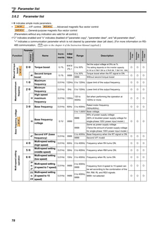
3.6 Parameter list .......................................................................................................... 75
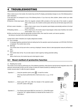
TROUBLESHOOTING .............................................................................. 101
4.1 Reset method of protective function .....................................................................101
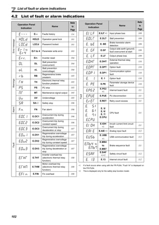
4.2 List of fault or alarm indications ............................................................................ 102
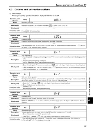
4.3 Causes and corrective actions..............................................................................103
4.4 Correspondences between digital and actual characters.....................................113
4.5 Check and clear of the faults history.....................................................................114
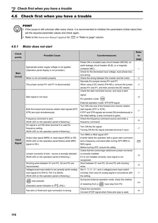
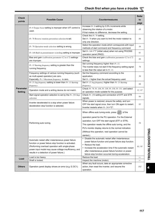
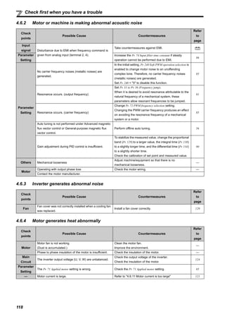
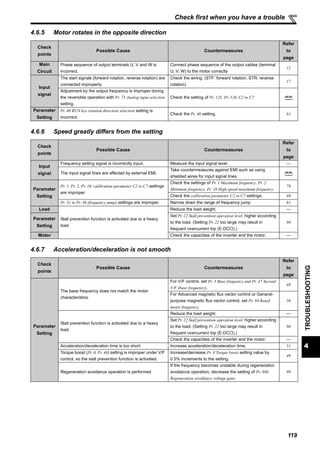
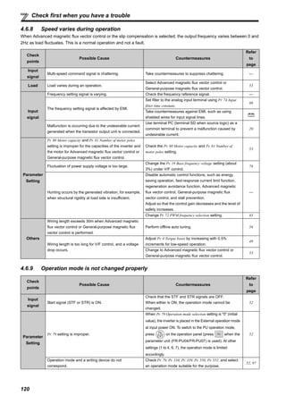
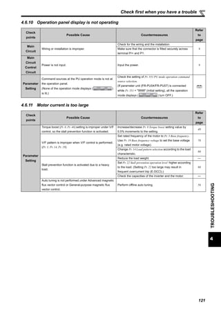
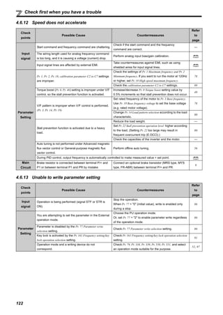
4.6 Check first when you have a trouble.....................................................................116
PRECAUTIONS FOR MAINTENANCE AND INSPECTION..................... 123
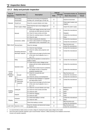
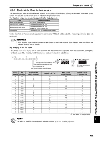
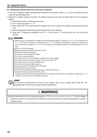
5.1 Inspection items ....................................................................................................123
SPECIFICATIONS..................................................................................... 131
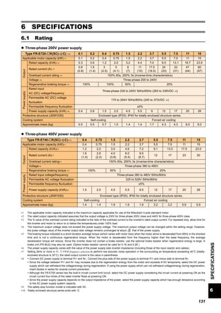
6.1 Rating.................................................................................................................... 131
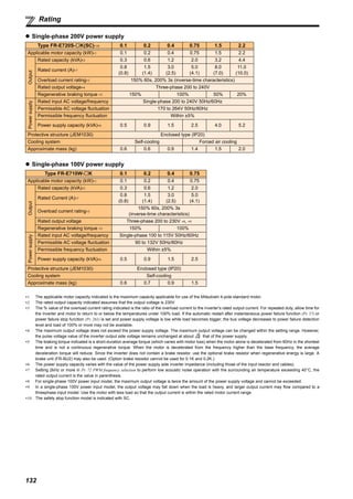
6.2 Common specifications.........................................................................................133
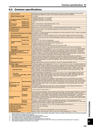
6.3 Outline dimension drawings..................................................................................134
APPENDIX................................................................................................. 139
Thank you for choosing this Mitsubishi Inverter.
This Instruction Manual (basic) is intended for users who "just want to run the inverter".
If you are going to utilize functions and performance, refer to the Instruction Manual (applied) [IB-0600277ENG]. The
Instruction Manual (applied) is separately available from where you purchased the inverter or your Mitsubishi sales
representative.
1
2
3
4
5
6](https://image.slidesharecdn.com/catalog-inverter-fr-e700-instruction-manual-basic-160425090732/85/Catalog-Inverter-FR-E700-instruction-manual-basic-Mitsubishi-Beeteco-com-1-320.jpg)
![I
1 PRODUCT CHECKING AND PARTS IDENTIFICATION 1
2 INSTALLATION AND WIRING 2
2.1 Peripheral devices ...................................................................................................3
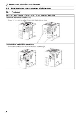
2.2 Removal and reinstallation of the cover ............................................................... 4
2.2.1 Front cover..................................................................................................................................... 4
2.2.2 Wiring cover................................................................................................................................... 6
2.3 Installation of the inverter and instructions .........................................................7
2.4 Wiring .......................................................................................................................9
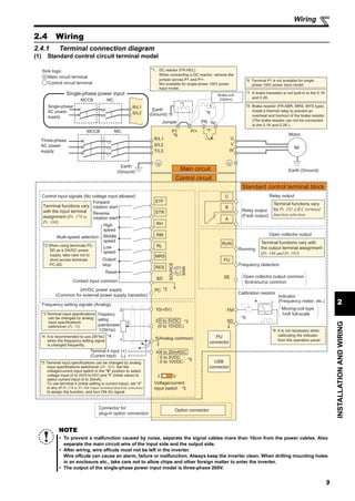
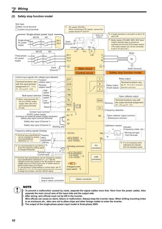
2.4.1 Terminal connection diagram ........................................................................................................ 9
2.4.2 Specification of main circuit terminal ........................................................................................... 11
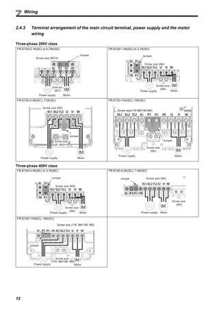
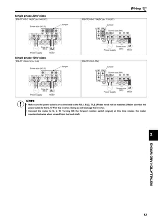
2.4.3 Terminal arrangement of the main circuit terminal, power supply and the motor wiring.............. 12
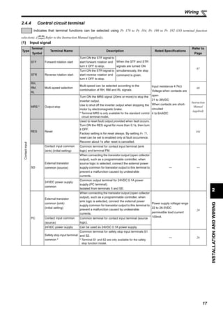
2.4.4 Control circuit terminal................................................................................................................. 17
2.4.5 Changing the control logic ........................................................................................................... 20
2.4.6 Wiring of control circuit ................................................................................................................ 22
2.4.7 Safety stop function (available only for the safety stop function model)...................................... 26
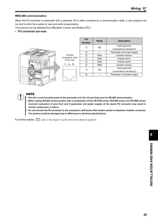
2.4.8 Connection to the PU connector.................................................................................................. 28
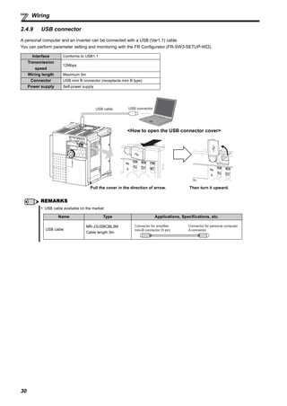
2.4.9 USB connector............................................................................................................................. 30
2.5 When using the brake resistor (MRS type, MYS type, FR-ABR) .......................31
2.6 Power-OFF and magnetic contactor (MC) ...........................................................32
2.7 Precautions for use of the inverter ......................................................................33
2.8 Failsafe of the system which uses the inverter .................................................. 35
3 DRIVE THE MOTOR 36
3.1 Step of operation ...................................................................................................36
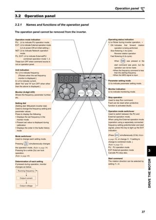
3.2 Operation panel ..................................................................................................... 37
3.2.1 Names and functions of the operation panel ............................................................................... 37
3.2.2 Basic operation (factory setting) .................................................................................................. 38
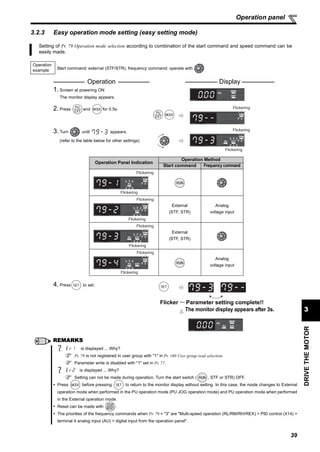
3.2.3 Easy operation mode setting (easy setting mode)....................................................................... 39
3.2.4 Operation lock (Press [MODE] for a while (2s))........................................................................... 40
3.2.5 Monitoring of output current and output voltage .......................................................................... 41
3.2.6 First priority monitor..................................................................................................................... 41
CONTENTS](https://image.slidesharecdn.com/catalog-inverter-fr-e700-instruction-manual-basic-160425090732/85/Catalog-Inverter-FR-E700-instruction-manual-basic-Mitsubishi-Beeteco-com-5-320.jpg)

![1
1
PRODUCTCHECKINGANDPARTSIDENTIFICATION
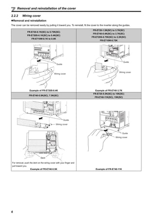
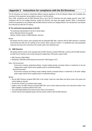
1 PRODUCT CHECKING AND PARTS IDENTIFICATION
Unpack the inverter and check the capacity plate on the front cover and the rating plate on the inverter side face to ensure that
the product agrees with your order and the inverter is intact.
Inverter model
• Accessory
· Fan cover fixing screws (M3 × 35mm)
These screws are necessary for compliance with the EU Directive (Refer to page 141)
Capacity Number
FR-E720-1.5K(SC) to 3.7K(SC), FR-E740-1.5K(SC) to 3.7K(SC), FR-E720S-0.75K(SC) to 2.2K(SC) 1
FR-E720-5.5K(SC) to 15K(SC), FR-E740-5.5K(SC) to 15K(SC) 2
Harmonic suppression guideline (when inverters are used in Japan)
All models of general-purpose inverters used by specific consumers are covered by "Harmonic suppression guideline for consumers who
receive high voltage or special high voltage". (For further details, refer to the chapter 3 of the Instruction Manual (applied).)
Connector for plug-in
option connection
(Refer to the instruction
manual of options.)
Inverter model
Serial number
Capacity plate *
FR-E740-3.7K
Rating plate *
Inverter model
Input rating
Output rating
Serial number
FR-E740-3.7K
E740 3.7 KFR - -
Represents the
inverter capacity [kW]E720 Three-phase 200V class
E740 Three-phase 400V class
E720S Single-phase 200V class
E710W Single-phase 100V class
No. Voltage class Control circuit terminal specificationSymbol
Standard control circuit terminal
(screw type)
No symbol
Safety stop function modelSC
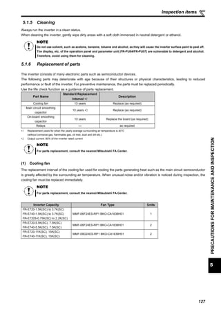
Cooling fan
(Refer to page 127)
USB connector
(mini-B connector)
(Refer to page 19)
Changing the control
logic jumper connector
(Refer to page 20)
Combed shaped wiring cover
(Refer to page 6)
Main circuit
terminal block
(Refer to page 11)
PU connector cover
(Refer to page 28)
Front cover
(Refer to page 4)
USB connector cover
(Refer to page 30)
Voltage/current input switch
(Refer to page 17)
Operation panel
(Refer to page 37)
PU connector
(Refer to page 19)
Example of FR-E740-3.7K
* Location of the capacity plate and the rating plate differs
according to the inverter capacity.
Refer to the outline dimension drawing. (Refer to page 134)
Control circuit terminal
block
(Refer to page 17)](https://image.slidesharecdn.com/catalog-inverter-fr-e700-instruction-manual-basic-160425090732/85/Catalog-Inverter-FR-E700-instruction-manual-basic-Mitsubishi-Beeteco-com-10-320.jpg)
![15
2
INSTALLATIONANDWIRING
Wiring
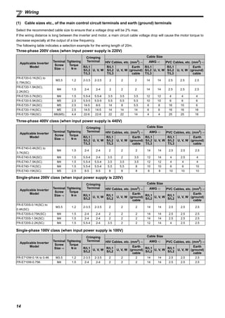
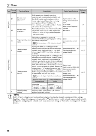
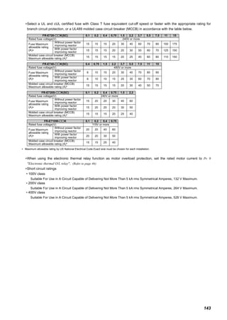
∗1 The cable size is that of the cable (HIV cable (600V class 2 vinyl-insulated cable) etc.) with continuous maximum permissible temperature of 75°C. Assumes
that the surrounding air temperature is 50°C or less and the wiring distance is 20m or less.
∗2 The recommended cable size is that of the cable (THHW cable) with continuous maximum permissible temperature of 75°C. Assumes that the surrounding air
temperature is 40°C or less and the wiring distance is 20m or less. (Selection example for use mainly in the United States.)
∗3 The recommended cable size is that of the cable (THHW cable) with continuous maximum permissible temperature of 70°C. Assumes that the surrounding air
temperature is 40°C or less and the wiring distance is 20m or less. (Selection example for use mainly in Europe.)
∗4 The terminal screw size indicates the terminal size for R/L1, S/L2, T/L3, U, V, W, and a screw for earthing (grounding).
A screw for earthing (grounding) of the FR-E720-15K(SC) is indicated in ( ).
For single-phase power input, the terminal screw size indicates the size of terminal screw for R/L1, S/L2, U, V, W, PR, P/+, N/-, P1 and a screw for earthing
(grounding).
The line voltage drop can be calculated by the following formula:
line voltage drop [V]=
Use a larger diameter cable when the wiring distance is long or when it is desired to decrease the voltage drop (torque
reduction) in the low speed range.
(2) Earthing (Grounding) precautions
NOTE
Tighten the terminal screw to the specified torque. A screw that has been tighten too loosely can cause a short circuit
or malfunction. A screw that has been tighten too tightly can cause a short circuit or malfunction due to the unit
breakage.
Use crimping terminals with insulation sleeve to wire the power supply and motor.
Leakage currents flow in the inverter. To prevent an electric shock, the inverter and motor must be earthed (grounded). This
inverter must be earthed (grounded). Earthing (Grounding) must conform to the requirements of national and local safety
regulations and electrical codes. (NEC section 250, IEC 536 class 1 and other applicable standards)
Use an neutral-point earthed (grounded) power supply for 400V class inverter in compliance with EN standard.
Use the dedicated earth (ground) terminal to earth (ground) the inverter. (Do not use the screw in the casing, chassis, etc.)
Use the thickest possible earth (ground) cable. Use the cable whose size is equal to or greater than that indicated on page
14 , and minimize the cable length. The earthing (grounding) point should be as near as possible to the inverter.
POINT
To be compliant with the EU Directive (Low Voltage Directive), earth (ground) the inverter according to the
instructions on page 141.
3 × wire resistance[mΩ/m] × wiring distance[m] × current[A]
1000](https://image.slidesharecdn.com/catalog-inverter-fr-e700-instruction-manual-basic-160425090732/85/Catalog-Inverter-FR-E700-instruction-manual-basic-Mitsubishi-Beeteco-com-24-320.jpg)
![38
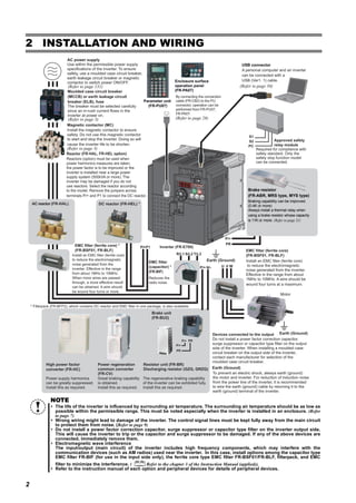
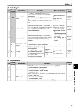
Operation panel
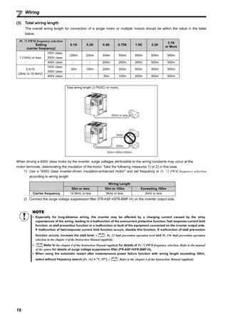
3.2.2 Basic operation (factory setting)
STOP
Operation mode switchover
ParametersettingFaultshistoryMonitor/frequencysetting
At powering ON (External operation mode)
PU operation mode
(output frequency monitor)
Parameter setting mode
PU Jog operation mode
Output current monitor Output voltage monitor
Display the
present setting
Value change
Value change
Parameter write is completed!!
Parameter and a setting value
flicker alternately.
Parameter clear All parameter
clear
Faults history clear
Initial value
change list
(Example)
(Example)
Frequency setting has been
written and completed!!
and frequency flicker.
[Operation for displaying faults history]
Past eight faults can be displayed.
(The latest fault is ended by ".".)
When no fault history exists, is displayed.
(Refer to page 42)
(Refer to page 114)](https://image.slidesharecdn.com/catalog-inverter-fr-e700-instruction-manual-basic-160425090732/85/Catalog-Inverter-FR-E700-instruction-manual-basic-Mitsubishi-Beeteco-com-47-320.jpg)
![40
Operation panel
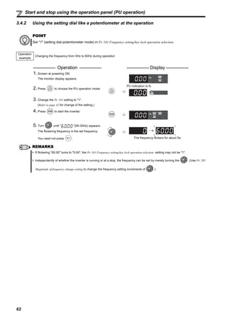
3.2.4 Operation lock (Press [MODE] for a while (2s))
Set "10 or 11" in Pr. 161, then press for 2s to make the setting dial and key operation invalid.
When the setting dial and key operation is invalid, appears on the operation panel. When the setting dial and key
operation is invalid, appears if the setting dial or key operation is performed. (When the setting dial or key
operation is not performed for 2s, the monitor display appears.)
To make the setting dial and key operation valid again, press for 2s.
Operation using the setting dial and key of the operation panel can be set invalid to prevent parameter change, and
unexpected start or frequency setting.
POINT
Set "10 or 11" (key lock valid) in Pr. 161 Frequency setting/key lock operation selection.
Operation Display
1.Screen at powering ON
The monitor display appears.
2.Press to choose the PU operation mode.
PU indication is lit.
3.Press to choose the parameter setting
mode.
PRM indication is lit.
(The parameter number read previously appears.)
4.Turn until (Pr. 161) appears.
5.Press to read the currently set value.
" " (initial value) appears.
6.Turn to change it to the set value " ".
7.Press to set.
Flicker ··· Parameter setting complete!!
8.Press for 2s to show the monitor mode.
Press for 2s.
Functions valid even in the
operation lock status
Stop and reset with .
Note
Release the operation lock to release the PU stop by key operation.](https://image.slidesharecdn.com/catalog-inverter-fr-e700-instruction-manual-basic-160425090732/85/Catalog-Inverter-FR-E700-instruction-manual-basic-Mitsubishi-Beeteco-com-49-320.jpg)
![43
DRIVETHEMOTOR
3
Operation panel
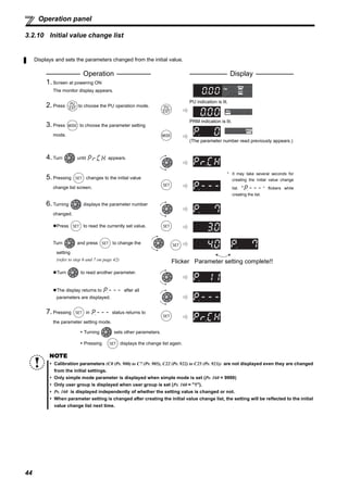
3.2.9 Parameter clear/all parameter clear
POINT
Set "1" in Pr.CL Parameter clear, ALLC all parameter clear to initialize all parameters. (Parameters are not cleared
when "1" is set in Pr. 77Parameter write selection.)
Refer to the extended parameter list on page 78 for parameters cleared with this operation.
Operation Display
1. Screen at powering ON
The monitor display appears.
2. Press to choose the PU operation mode.
PU indication is lit.
3. Press to choose the parameter setting
mode.
PRM indication is lit.
(The parameter number read previously appears.)
4. Turn until ( ) appears.
Parameter clear
All parameter clear
5. Press to read the currently set value.
" "(initial value) appears.
6. Turn to change it to the set value " ".
7. Press to set.
Parameter clear
All parameter clear
Flicker ··· Parameter setting complete!!
Turn to read another parameter.
Press to show the setting again.
Press twice to show the next parameter.
Setting Description
0 Not executed.
1
Set parameters back to the initial values. (Parameter clear sets back all parameters except
calibration parameters, terminal function selection parameters to the initial values.) Refer to the
parameter list on page 78 for availability of parameter clear and all parameter clear.
REMARKS
are displayed alternately ... Why?
The inverter is not in the PU operation mode.
Is PU connector or USB connector used?
1. Press . [PU] is lit and the monitor (4 digit LED) displays "1". (When Pr. 79 = "0" (initial value))
2. Carry out operation from step 6 again.
and](https://image.slidesharecdn.com/catalog-inverter-fr-e700-instruction-manual-basic-160425090732/85/Catalog-Inverter-FR-E700-instruction-manual-basic-Mitsubishi-Beeteco-com-52-320.jpg)
![45
DRIVETHEMOTOR
3
Simplemodeparameterlist
Before operation
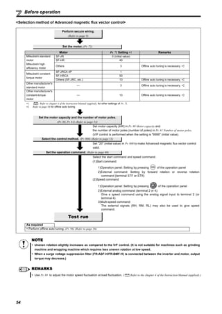
3.3 Before operation
3.3.1 Simple mode parameter list
For simple variable-speed operation of the inverter, the initial setting of the parameters may be used as they are. Set the
necessary parameters to meet the load and operational specifications. Parameter setting, change and check can be made
from the operation panel. (For details of parameters, refer to the chapter 4 of the Instruction Manual (applied)).
POINT
Only simple mode parameter can be displayed using Pr. 160 User group read selection. (All parameters are displayed
with the initial setting. Set Pr. 160 User group read selection as required. (Refer to page 42 for parameter change)
Pr. 160 Description
9999 Parameters classified as simple mode can be displayed.
0
(initial value)
Both the parameters classified as simple mode and the parameters
classified as extended mode can be displayed.
1 Only the parameters registered to the user group can be displayed.
Parameter
Number
Name Unit
Initial
Value
Range Application
Reference
Page
0 Torque boost 0.1%
6%/4%/3%/
2%∗
0 to 30%
Set when you want to increase a
starting torque or when the motor
with a load will not rotate, resulting in
an alarm [OL] and a trip [OC1].
∗ Initial values differ according to the
inverter capacity. (0.75K or less/
1.5K to 3.7K/5.5K, 7.5K/11K, 15K)
49
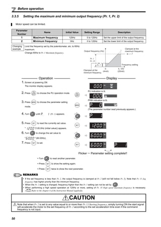
1 Maximum frequency 0.01Hz 120Hz 0 to 120Hz
Set when the maximum output
frequency need to be limited.
50
2 Minimum frequency 0.01Hz 0Hz 0 to 120Hz
Set when the minimum output
frequency need to be limited.
3 Base frequency 0.01Hz 60Hz 0 to 400Hz
Set when the rated motor
frequency is 50Hz.
Check the motor rating plate.
48
4
Multi-speed setting
(high speed)
0.01Hz 60Hz 0 to 400Hz
Set when changing the preset
speed in the parameter with a
terminal.
695
Multi-speed setting
(middle speed)
0.01Hz 30Hz 0 to 400Hz
6
Multi-speed setting (low
speed)
0.01Hz 10Hz 0 to 400Hz
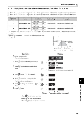
7 Acceleration time 0.1s 5s/10s/15s∗ 0 to 3600s
Acceleration/deceleration time can
be set.
∗ Initial values differ according to the
inverter capacity. (3.7K or less/
5.5K, 7.5K/11K, 15K)
51
8 Deceleration time 0.1s 5s/10s/15s∗ 0 to 3600s
9
Electronic thermal O/L
relay
0.01A
Rated
inverter
current
0 to 500A
The inverter protects the motor
from overheat.
Set the rated motor current.
46
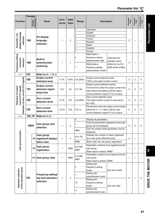
79
Operation mode
selection
1 0
0, 1, 2, 3, 4, 6,
7
Select the start command location
and frequency command location.
52
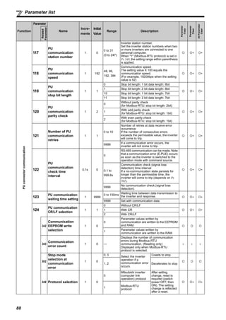
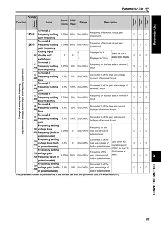
125
Terminal 2 frequency
setting gain frequency
0.01Hz 60Hz 0 to 400Hz
Frequency for the maximum value
of the potentiometer (5V initial
value) can be changed.
72
126
Terminal 4 frequency
setting gain frequency
0.01Hz 60Hz 0 to 400Hz
Frequency for the maximum
current input (20mA initial value)
can be changed.
74
160
User group read
selection
1 0 0, 1, 9999
Parameter which can be read from
the operation panel and parameter
unit can be restricted.
—](https://image.slidesharecdn.com/catalog-inverter-fr-e700-instruction-manual-basic-160425090732/85/Catalog-Inverter-FR-E700-instruction-manual-basic-Mitsubishi-Beeteco-com-54-320.jpg)
![49
DRIVETHEMOTOR
3
Before operation
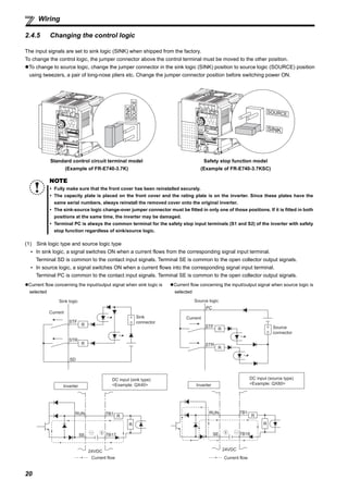
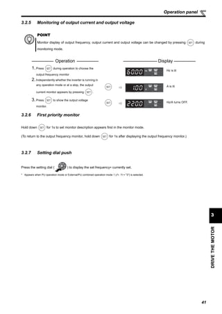
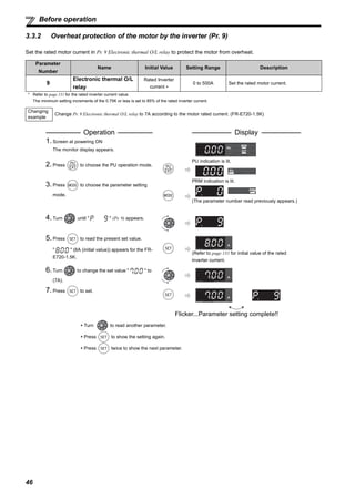
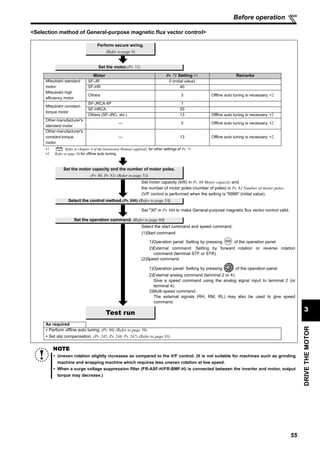
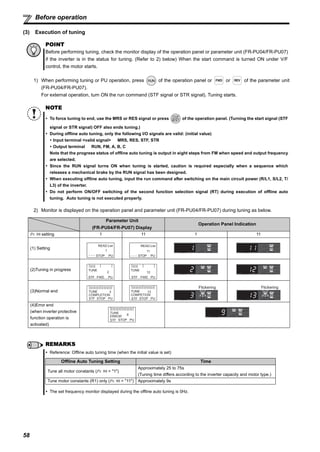
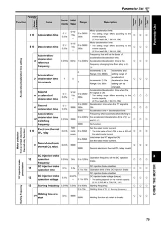
3.3.4 Increasing the starting torque (Pr. 0)
Set this parameter when "the motor with a load will not rotate", "an alarm [OL] is output, resulting in an inverter trip due to [OC1]," etc.
Parameter
Number
Name Initial Value Setting Range Description
0 Torque boost
0.1K to 0.75K 6%
0 to 30%
Motor torque in the low-frequency range can be adjusted
to the load to increase the starting motor torque.
1.5K to 3.7K 4%
5.5K, 7.5K 3%
11K, 15K 2%
Changing
example
When the motor will not rotate, increase the Pr. 0 value by 1% by 1%
by looking at the motor movement. (The guideline is for about 10%
change at the greatest.
Operation Display
1. Screen at powering ON
The monitor display appears.
2. Press to choose the PU operation mode.
PU indication is lit.
3. Press to choose the parameter setting
mode.
PRM indication is lit.
(The parameter number read previously appears.)
4. Turn until (Pr. 0) appears.
5. Press to read the currently set value.
" " (6.0%(initial value)) appears for the 0.75K
or less. (The initial value differs according to the capacity.)
6. Turn to change the set value to " "
(7.0%).
7. Press to set.
Flicker ··· Parameter setting complete!!
Turn to read another parameter.
Press to show the setting again.
Press twice to show the next parameter.
Note
The amount of current flows in the motor may become large according to the conditions such as the motor
characteristics, load, acceleration/deceleration time, wiring length, etc. After overcurrent trip (OL (overcurrent
alarm)), E.OC1 (overcurrent trip during acceleration), overload trip (E.THM (motor overload trip), or E.THT (inverter
overload trip)) may occur.
(When a fault occurs, release the start command, and decrease the Pr. 0 setting 1% by 1% to reset.) (Refer to page 101.)
POINT
If the inverter still does not operate properly after the above measures, set Pr. 80, Pr. 81, and Pr. 800 (Advanced
magnetic flux vector control). The Pr. 0 setting is invalid under Advanced magnetic flux vector control. ( Refer
to the chapter 4 of the Instruction Manual (applied)).
V/FV/FV/F
Outputvoltage
Pr. 0
Pr. 46
Setting range
Output
frequency
(Hz)
Base
frequency
0
100%](https://image.slidesharecdn.com/catalog-inverter-fr-e700-instruction-manual-basic-160425090732/85/Catalog-Inverter-FR-E700-instruction-manual-basic-Mitsubishi-Beeteco-com-58-320.jpg)
![63
DRIVETHEMOTOR
3
Start and stop using the operation panel (PU operation)
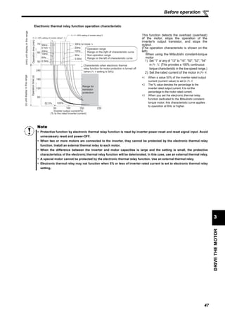
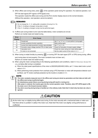
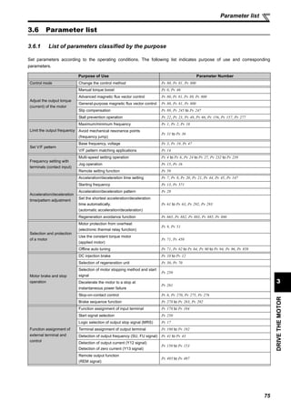
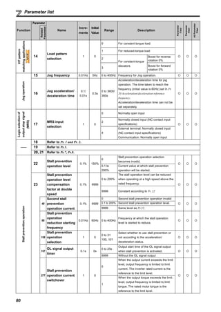
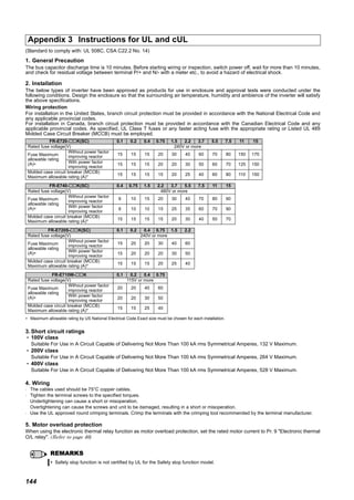
3.4.3 Setting the frequency by switches (three-speed setting) (Pr. 4 to Pr. 6)
POINT
Operation panel ( ) is used to give a start command.
To give a frequency command, terminal between SD and RH, RM, or RL is turned ON.(three-speed setting)
Pr. 79 Operation mode selection must be set to "4" (External/PU combination operation mode 2).
[Connection diagram]
Operation
example
Operation at low speed (10Hz)
Operation Display
1.Screen at powering ON
The monitor display appears.
2.Change the Pr. 79 setting to "4". (Refer to page 39 for change of the setting.)
[PU] display and [EXT] display are lit.
3.Start
Turn ON the low-speed switch (RL).
4.Acceleration → constant speed
Press to start running.
The frequency value on the indication increases
according to Pr. 7 Acceleration time, until “ “
(10.00Hz) is displayed.
[RUN] indication is lit during forward rotation and
flickers slowly during reverse rotation.
5.Deceleration
Press to stop
The frequency value on the indication decreases
according to Pr. 8 Deceleration time and displays
" " (0.00Hz) when the motor is stopped.
6.Stop
Turn OFF the low-speed switch (RL).
Inverter
Operation
panel
High speed
Middle speed
Low speed
SD
RH
RM
RL
Speed 1
(High speed)
Speed 2
(Middle speed)
Speed 3
(Low speed)
ON
ON
ON
Time
Outputfrequency(Hz)
RL
RH
RM
Low
speed
ON
Middle
speed
High
speed
Stop
OFF
Low
speed
Middle
speed
High
speed](https://image.slidesharecdn.com/catalog-inverter-fr-e700-instruction-manual-basic-160425090732/85/Catalog-Inverter-FR-E700-instruction-manual-basic-Mitsubishi-Beeteco-com-72-320.jpg)
![64
Start and stop using the operation panel (PU operation)
REMARKS
The initial values of the terminals RH, RM, RL are 60Hz, 30Hz, and 10Hz. (Use Pr. 4, Pr. 5 and Pr. 6 (Refer to page 69) to change.)
In the initial setting, when two or more of multi-speed settings are simultaneously selected, priority is given to the set frequency
of the lower signal.
For example, when the RH and RM signals turn ON, the RM signal (Pr. 5 ) has a higher priority.
Maximum of 15-speed operation can be performed. ( Refer to the chapter 4 of the Instruction Manual (applied).)
60Hz for the RH, 30Hz for the RM and 10Hz for the RL are not output when they are turned ON ... Why?
Check for the setting of Pr. 4, Pr. 5, and Pr. 6 once again.
Check for the setting of Pr. 1 Maximum frequency and Pr. 2 Minimum frequency once again. (Refer to page 50)
Check that Pr. 180 RL terminal function selection = "0", Pr. 181 RM terminal function selection = "1", Pr. 182 RH terminal function
selection = "2" and Pr. 59 Remote function selection = "0". (all are initial values)
[RUN] is not light ... Why?
Check that wiring is correct. Check it again.
Check for the Pr. 79 setting once again. (Pr. 79 must be set to "4"). (Refer to page 52)
Change the frequency of the terminal RL, RM, and RH.
Refer to page 69 to change the running frequency at each terminal in Pr. 4 Multi-speed setting (high speed), Pr. 5 Multi-speed
setting (middle speed), and Pr. 6 Multi-speed setting (low speed).](https://image.slidesharecdn.com/catalog-inverter-fr-e700-instruction-manual-basic-160425090732/85/Catalog-Inverter-FR-E700-instruction-manual-basic-Mitsubishi-Beeteco-com-73-320.jpg)
![65
DRIVETHEMOTOR
3
Start and stop using the operation panel (PU operation)
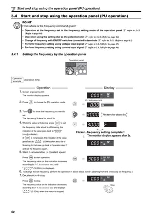
3.4.4 Setting the frequency by analog input (voltage input)
POINT
Operation panel ( ) is used to give a start command.
Frequency command is given from the potentiometer (by connecting terminal 2 and 5.)
Pr. 79 Operation mode selection must be set to "4" (External/PU combination operation mode 2).
[Connection diagram]
(The inverter supplies 5V of power to the frequency setting potentiometer. (terminal 10))
Operation
example
Operate at 60Hz.
Operation Display
1. Screen at powering ON
The monitor display appears.
2. Change the Pr. 79 setting to "4".
(Refer to page 39 for change of the setting.)
[PU] display and [EXT] display are lit.
3. Start
Press .
[RUN] flickers fast as no frequency command is
given.
4. Acceleration constant speed
Turn the potentiometer clockwise slowly to full.
The frequency value on the indication
increases according to Pr. 7 Acceleration time
until " " (60.00Hz) is displayed.
[RUN] display is lit during forward rotation operation
and flickers slowly during reverse rotation
operation.
5. Deceleration
Turn the potentiometer counterclockwise slowly
to full.
The frequency value on the indication decreases
according to Pr. 8 Deceleration time and displays
" " (0.00Hz) when the motor is stopped.
[RUN] flickers fast.
6. Stop
Press .
[RUN] turns OFF.
REMARKS
Change the frequency (60Hz) at the maximum voltage input (5V initial value)
Adjust the frequency in Pr. 125 Terminal 2 frequency setting gain frequency. (Refer to page 72)
Change the frequency (0Hz) at the minimum voltage input (0V initial value)
Adjust the frequency in calibration parameter C2 Terminal 2 frequency setting bias frequency. ( Refer to the chapter 4 of the
Instruction Manual (applied).)
Frequency setting
potentiometer
Inverter
Operation
panel
5
10
2
Flickering
Flickering
Stop](https://image.slidesharecdn.com/catalog-inverter-fr-e700-instruction-manual-basic-160425090732/85/Catalog-Inverter-FR-E700-instruction-manual-basic-Mitsubishi-Beeteco-com-74-320.jpg)
![66
Start and stop using the operation panel (PU operation)
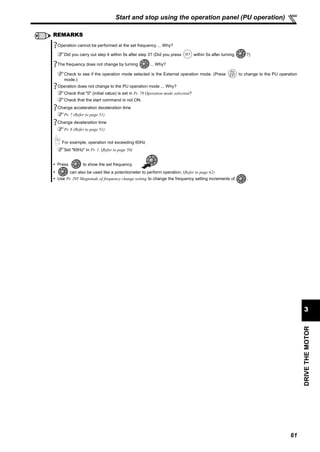
3.4.5 Setting the frequency by analog input (current input)
POINT
Operation panel ( ) is used to give a start command.
Frequency command is given by current input (across terminals 4 and 5.)
Turn the AU signal ON.
Pr. 79 Operation mode selection must be set to "4" (External/PU combination operation mode 2).
[Connection diagram]
Operation
example
Operate at 60Hz.
Operation Display
1. Screen at powering ON
The monitor display appears.
2. Change the Pr. 79 setting to "4".
(Refer to page 39 for change of the setting.
[PU] display and [EXT] display are lit.
3. Start
Check that the terminal 4 input selection signal
(AU) is ON.
Press .
[RUN] flickers fast as no frequency command is
given.
4. Acceleration constant speed
Perform 20mA input.
The frequency value on the indication
increases according to Pr. 7 Acceleration time
until " "(60.00Hz) is displayed.
[RUN] display is lit during forward rotation
operation and flickers slowly during reverse
rotation operation.
5. Deceleration
Perform 4mA input.
The frequency value on the indication decreases
according to Pr. 8 Deceleration time and displays
" " (0.00Hz) when the motor is stopped.
[RUN] flickers fast.
6. Stop
Press .
[RUN] turns OFF.
REMARKS
Set "4" in Pr. 178 to Pr. 184 (input terminal function selection) to assign terminal 4 input selection signal (AU) to the input terminal.
( Refer to the chapter 4 of the Instruction Manual (applied).)
Change the frequency (60Hz) at the maximum current input (at 20mA, initial value)
Adjust the frequency in Pr. 126 Terminal 4 frequency setting gain frequency. (Refer to page 74)
Change the frequency (0Hz) at the minimum current input (at 4mA, initial value)
Adjust the frequency in calibration parameter C5 Terminal 4 frequency setting bias frequency. ( Refer to the chapter 4 of the
Instruction Manual (applied).)
Operation
panel
5(-)
4(+)Current signal
source
(4 to 20mADC)
SD
AU (terminal RH)AU signal
Flickering
Current signal
source
(4 to 20mADC)
Current signal
source
(4 to 20mADC)
Flickering
Stop](https://image.slidesharecdn.com/catalog-inverter-fr-e700-instruction-manual-basic-160425090732/85/Catalog-Inverter-FR-E700-instruction-manual-basic-Mitsubishi-Beeteco-com-75-320.jpg)
![67
DRIVETHEMOTOR
3
Start and stop using terminals (External operation)
3.5 Start and stop using terminals (External operation)
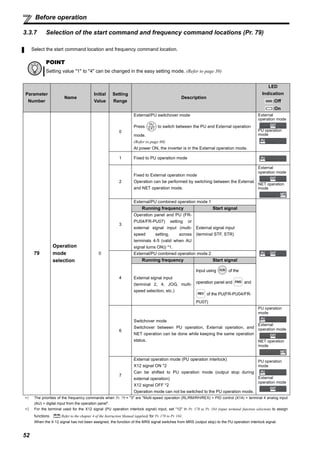
3.5.1 Setting the frequency by the operation panel (Pr. 79 = 3)
POINT
From where is the frequency command given?
Operation at the frequency set in the frequency setting mode of the operation panel refer to 3.5.1 (Refer to page 67)
Give a frequency command by switch (multi-speed setting) refer to 3.5.2 (Refer to page 69)
Perform frequency setting by a voltage input signal refer to 3.5.3 (Refer to page 71)
Perform frequency setting by a current input signal refer to 3.5.5 (Refer to page 73)
POINT
Switch terminal STF(STR)-SD ON to give a start command.
Operation panel ( ) is used to give a frequency command.
Set "3" (External/PU combined operation mode 1) in Pr. 79 .
Operation
example
Operate at 30Hz.
Operation Display
1. Screen at powering ON
The monitor display appears.
2. Change the Pr. 79 setting to "3". (Refer to page 39 for change of the setting.)
[PU] display and [EXT] display are lit.
3. Turn to change running frequency. Display the
frequency you want to set.
The frequency flickers for about 5s.
4. While the value is flickering, press to set the
frequency. After about 3s of flickering, the indication of
the value goes back to " " (monitor display).
(If is not pressed, the indication of the value goes
back to " " (0.00Hz) after about 5s of flickering. In
that case, go back to "operation step 3" and set the
frequency again.)
Flicker...frequency setting complete!!
The monitor display appears after 3s.
5. Start acceleration constant speed
Turn ON the start switch (STF or STR).
The frequency indicated on the indication increases
by the Pr.7 Acceleration time, and " "
(30.00Hz) appears.
[RUN] indication is lit during forward rotation, and
flickers during reverse rotation.
6. To change the set frequency, perform the operation in above steps 3 and 4. (Setting starts from the previously set frequency.)
SD
STF
STR
Inverter
Operation
panelForward rotation start
Reverse rotation start
[Connection diagram]
Flickers for about 5s
Forward
rotation
Reverse
rotationON](https://image.slidesharecdn.com/catalog-inverter-fr-e700-instruction-manual-basic-160425090732/85/Catalog-Inverter-FR-E700-instruction-manual-basic-Mitsubishi-Beeteco-com-76-320.jpg)
![68
Start and stop using terminals (External operation)
7. Deceleration Stop
Turn OFF the start switch (STF or STR).
The frequency value on the indication decreases
according to Pr. 8 Deceleration time and displays
" " (0.00Hz) when the motor is stopped.
[RUN] turns OFF.
REMARKS
Pr. 178 STF terminal function selection must be set to "60" (or Pr. 179 STR terminal function selection must be set to "61").
(all are initial values)
When Pr. 79 Operation mode selection is set to "3", multi-speed operation (Refer to page 69) is also valid.
Pressing to stop the motor and the display shows .
1. Turn the start switch (STF or STR) OFF.
2. The display can be reset by .
Operation Display
Forward
rotation Reverse
rotationOFF
Stop](https://image.slidesharecdn.com/catalog-inverter-fr-e700-instruction-manual-basic-160425090732/85/Catalog-Inverter-FR-E700-instruction-manual-basic-Mitsubishi-Beeteco-com-77-320.jpg)
![69
DRIVETHEMOTOR
3
Start and stop using terminals (External operation)
3.5.2 Setting the frequency by switches (three-speed setting) (Pr. 4 to Pr. 6)
POINT
To give a start command, terminal between SD and STF (STR) is turned ON.
To give a frequency command, terminal between SD and terminal RH, RM, or RL is turned ON.
Operation
example
Operation at high speed (60Hz)
Operation Display
1. Screen at powering ON
The monitor display appears.
2. Start
Turn ON the high-speed switch (RH).
3. Acceleration constant speed
Turn ON the start switch (STF or STR). The
frequency on the indication increases
according to Pr.7 Acceleration time, until
" " (60.00Hz) is displayed.
[RUN] indication is lit during forward rotation,
and flickers during reverse rotation.
When RM is turned ON, 30Hz is displayed.
When RL is turned ON, 10Hz is displayed.
4. Deceleration
Turn OFF the start switch (STF or STR).
The frequency value on the indication decreases
according to Pr. 8 Deceleration time and displays
" " (0.00Hz) when the motor is stopped.
[RUN] turns OFF.
5. Stop
Turn OFF the high-speed switch (RH).
Inverter
Forward rotation start
Reverse rotation start
High speed
RM
STF
STR
RH
Middle speed
Low speed
SD
RL
[Connection diagram]
ON
ON
ON
Outputfrequency(Hz)
Speed 1
(High speed)
Speed 2
(Middle speed)
Speed 3
(Low speed)
RH
RM
RL
Time
ON
High speed
Middle speed
Low speedON
Forward
rotation
Reverse
rotationON
Forward
rotation Reverse
rotationOFF Stop
High speed
Middle speed
Low speedOFF](https://image.slidesharecdn.com/catalog-inverter-fr-e700-instruction-manual-basic-160425090732/85/Catalog-Inverter-FR-E700-instruction-manual-basic-Mitsubishi-Beeteco-com-78-320.jpg)
![70
Start and stop using terminals (External operation)
REMARKS
Initial value of terminal RH, RM, and RL are 60Hz, 30Hz, and 10Hz. (To change, set Pr.4, Pr.5, and Pr.6.)
In the initial setting, when two or more of multi-speed settings are simultaneously selected, priority is given to the set frequency
of the lower signal. For example, when the RH and RM signals turn ON, the RM signal (Pr.5) has a higher priority.
Maximum of 15-speed operation can be performed. ( Refer to the chapter 4 of the Instruction Manual (applied))
[EXT] is not lit even when is pressed...Why?
Switchover of the operation mode with is valid when Pr. 79 = "0" (initial value).
50Hz for the RH, 30Hz for the RM and 10Hz for the RL are not output when they are turned ON...Why?
Check for the setting of Pr. 4, Pr. 5, and Pr. 6 once again.
Check for the setting of Pr. 1 Maximum frequency and Pr. 2 Minimum frequency once again. (Refer to page 50)
Check for the Pr. 79 setting once again. Pr. 79 must be set to "0" or "2". (Refer to page 52)
Check that Pr. 180 RL terminal function selection ="0", Pr. 181 RM terminal function selection ="1", Pr. 182 RH terminal function
selection ="2" and Pr. 59 Remote function selection ="0". (all are initial values)
[RUN] is not light...Why?
Check that wiring is correct. Check it again.
Check that "60" is set in Pr. 178 STF terminal function selection (or "61" is set in Pr. 179 STR terminal function selection). (all are
initial values)
How is the frequency setting from 4 to 7 speed?
The setting differs according to Pr. 24 to Pr. 27 (multi-speed setting). Refer to the chapter 4 of the Instruction Manual
(applied).
Perform multi-speed operation more than 8 speed...How?
Use the REX signal to perform the operation. Refer to the chapter 4 of the Instruction Manual (applied).](https://image.slidesharecdn.com/catalog-inverter-fr-e700-instruction-manual-basic-160425090732/85/Catalog-Inverter-FR-E700-instruction-manual-basic-Mitsubishi-Beeteco-com-79-320.jpg)
![71
DRIVETHEMOTOR
3
Start and stop using terminals (External operation)
3.5.3 Setting the frequency by analog input (voltage input)
POINT
To give a start command, terminal between SD and STF (STR) is turned ON.
Frequency command is given from the potentiometer (by connecting terminal 2 and 5.)
[Connection diagram]
(The inverter supplies 5V of power to the frequency setting potentiometer. (terminal 10))
Operation
example
Operate at 60Hz.
Operation Display
1.Screen at powering ON
The monitor display appears.
2.Start
Turn the start switch (STF or STR) ON.
[RUN] flickers fast as no frequency command is
given.
3.Acceleration constant speed
Turn the potentiometer (frequency setting
potentiometer) clockwise slowly to full.
The frequency value on the indication
increases according to Pr. 7 Acceleration time
until " "(60.00Hz) is displayed.
[RUN] display is lit during forward rotation
operation and flickers slowly during reverse
rotation operation.
4.Deceleration
Turn the potentiometer (frequency setting
potentiometer) counterclockwise slowly to full.
The frequency value on the indication
decreases according to Pr.8 Deceleration time
and displays " " (0.00Hz) when the motor
is stopped.
[RUN] flickers fast.
5.Stop
Turn the start switch (STF or STR) OFF.
[RUN] turns OFF.
Frequency setting
potentiometer
Inverter
5
10
2
Forward rotation start
Reverse rotation start
STF
STR
SD
ON
Forward
rotation
Reverse
rotationON
Flickering
Flickering
Stop
Forward
rotation Reverse
rotationOFF](https://image.slidesharecdn.com/catalog-inverter-fr-e700-instruction-manual-basic-160425090732/85/Catalog-Inverter-FR-E700-instruction-manual-basic-Mitsubishi-Beeteco-com-80-320.jpg)
![72
Start and stop using terminals (External operation)
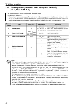
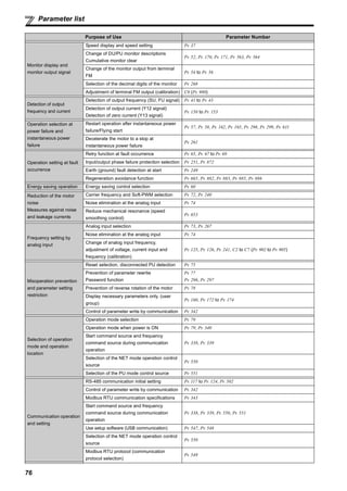
3.5.4 Changing the output frequency (60Hz initial value) at the maximum voltage input
(5V initial value)
< How to change the maximum frequency>
REMARKS
Pr. 178 STF terminal function selection must be set to "60" (or Pr. 179 STR terminal function selection must be set to "61"). (all are initial
values)
The motor will not rotate...Why?
Check that [EXT] is lit.
[EXT] is valid when Pr. 79 = "0" (initial value) or "2".
Use to lit [EXT].
Check that wiring is correct. Check it again.
Change the frequency (0Hz) of the minimum value of the potentiometer (0V initial value)
Adjust the frequency in calibration parameter C2 Terminal 2 frequency setting bias frequency. ( Refer to the chapter 4 of the
Instruction Manual (applied)).
Changing
example
When you use the 0 to 5VDC input and want to change the frequency at 5V from 60Hz (initial value) to 50Hz,
set "50Hz" in Pr. 125.
Operation Display
1. Turn until " " (Pr. 125) appears.
2. Press to show the present set value
" " (60.00Hz).
3. Turn to change the set value to
" "(50.00Hz).
4. Press to set.
Flicker...50Hz output at 5V input complete!!
5. Mode/monitor check
Press twice to choose the monitor/
frequency monitor.
6. To check the setting, turn the start switch (STF or STR) ON
and input 5V (turn the potentiometer clockwise slowly to full).
(Refer to operation 2 to 5 of the section 3.5.3)
REMARKS
To change the value to more than 120Hz, the maximum frequency must be set to more than 120Hz.
The frequency meter (indicator) connected across terminals FM-SD does not indicate exactly 50Hz ... Why?
The frequency meter can be adjusted using calibration parameter C0 FM terminal calibration. ( Refer to the chapter 4 of
the Instruction Manual (applied)).
Use calibration parameter C2 to set frequency at 0V and
calibration parameter C0 to adjust the indicator.
( Refer to the chapter 4 of the Instruction Manual (applied)).
As other adjustment methods of frequency setting voltage gain, there are methods to adjust with a voltage applied to across
terminals 2-5 and adjust at any point without a voltage applied. ( Refer to the Instruction Manual (applied) for the setting
method of calibration parameter C4.)
Initial value
Bias
C2 (Pr. 902)
0
0
Frequency
setting signal
100%
10V
0 5V
C3 (Pr. 902) C4 (Pr. 903)
Gain
Pr. 125
Output
frequency
(Hz)
60Hz](https://image.slidesharecdn.com/catalog-inverter-fr-e700-instruction-manual-basic-160425090732/85/Catalog-Inverter-FR-E700-instruction-manual-basic-Mitsubishi-Beeteco-com-81-320.jpg)
![73
DRIVETHEMOTOR
3
Start and stop using terminals (External operation)
3.5.5 Setting the frequency by analog input (current input)
POINT
Switch terminal STF(STR)-SD ON to give a start command.
Frequency command is given by current input (across terminals 4 and 5.)
Turn ON the AU signal.
Set "2" (External operation mode) in Pr. 79 Operation mode selection.
[Connection diagram]
Operation
example
Operate at 60Hz.
Operation Display
1.Screen at powering ON
The monitor display appears.
2.Start
Turn the start switch (STF or STR) ON.
[RUN] flickers fast as no frequency command is
given.
3.Acceleration constant speed
Perform 20mA input.
The frequency value on the indication
increases according to Pr. 7 Acceleration time
until " "(60.00Hz) is displayed.
[RUN] display is lit during forward rotation
operation and flickers slowly during reverse
rotation operation.
4.Deceleration
Perform 4mA input.
The frequency value on the indication
decreases according to Pr.8 Deceleration time
and displays " " (0.00Hz) when the motor
is stopped.
[RUN] flickers fast.
5.Stop
Turn the start switch (STF or STR) OFF.
[RUN] turns OFF.
Inverter
5(-)
4(+)
SD
AU signal (terminal RH)AU signal
Forward rotation start
Reverse rotation start
STF
STR
Current signal
source
(4 to 20mADC)
ON
Forward
rotation
Reverse
rotationON
Flickering
Current signal
source
(4 to 20mADC)
Current signal
source
(4 to 20mADC)
Flickering
Stop
Forward
rotation Reverse
rotationOFF](https://image.slidesharecdn.com/catalog-inverter-fr-e700-instruction-manual-basic-160425090732/85/Catalog-Inverter-FR-E700-instruction-manual-basic-Mitsubishi-Beeteco-com-82-320.jpg)
![74
Start and stop using terminals (External operation)
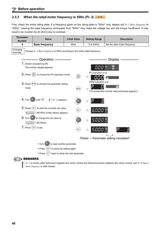
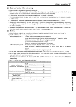
3.5.6 Changing the output frequency (60Hz initial value) at the maximum current input
(at 20mA, initial value)
<How to change the maximum frequency>
REMARKS
Set "4" in Pr.178 to Pr.184 (input terminal function selection) to assign terminal 4 input selection signal (AU) to the input terminal.
( Refer to the chapter 4 of the Instruction Manual (applied)).
The motor will not rotate...Why?
Check that [EXT] is lit.
[EXT] is valid when Pr. 79 = "0" (initial value) or "2".
Use to lit [EXT].
Check that the AU signal is ON.
Turn the AU signal ON.
Check that wiring is correct. Check it again.
Change the frequency (0Hz) at the minimum current input (at 4mA, initial value)
Adjust the frequency in calibration parameter C5 Terminal 4 frequency setting bias frequency. ( Refer to the chapter 4 of the
Instruction Manual (applied)).
Changing
example
When you use the 4 to 20mA input and want to change the frequency at 20mA from 60Hz (initial value) to 50Hz,
set "50Hz" in Pr. 126.
Operation Display
1. Turn until " " (Pr. 126) appears.
2. Press to show the currently set value
" " (60.00Hz).
3. Turn to change the set value to
" " (50.00Hz).
4. Press to set.
Flicker...50Hz output at 20mA input complete!!
5. Mode/monitor check
Press twice to choose the monitor/
frequency monitor.
6. To check the setting, turn the start switch (STF or STR) ON
and input 20mA. (Refer to operation 2 to 5 of the section 3.5.5)
REMARKS
The frequency meter (indicator) connected to across terminals FM-SD does not indicate just 50Hz ... Why?
The frequency meter can be adjusted using calibration parameter C0 FM terminal calibration. ( Refer to the chapter 4 of
the Instruction Manual (applied)).
Use calibration parameter C5 to set frequency at 4mA and
calibration parameter C0 to adjust the indicator.
( Refer to the chapter 4 of the Instruction Manual (applied)).
As other adjustment methods of frequency setting voltage gain, there are methods to adjust with a voltage applied to across
terminals 4-5 and adjust at any point without a voltage applied. ( Refer to the Instruction Manual (applied) for the setting
method of calibration parameter C7).
When performing a high speed operation at 120Hz or more, setting of Pr. 18 High speed maximum frequency is necessary.
( Refer to the chapter 4 of the Instruction Manual (applied) ).
Output
frequency
(Hz)
60Hz
Initial value
Bias
C5 (Pr. 904)
Gain
Pr. 126
0 Frequency
setting signal
100%
0
20
4 20mA
C6 (Pr. 904) C7 (Pr. 905)](https://image.slidesharecdn.com/catalog-inverter-fr-e700-instruction-manual-basic-160425090732/85/Catalog-Inverter-FR-E700-instruction-manual-basic-Mitsubishi-Beeteco-com-83-320.jpg)

![85
DRIVETHEMOTOR
3
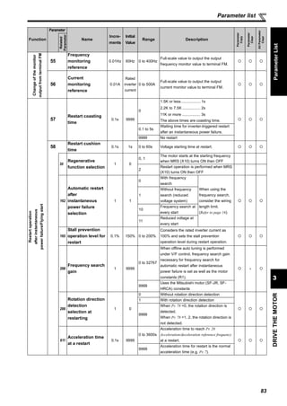
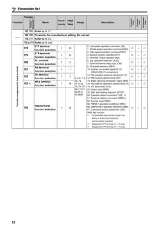
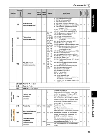
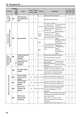
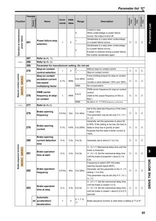
Parameter list
ParameterList
Motorselection(appliedmotor)
71
Applied motor 1 0
0
Thermal characteristics of a standard
motor
1
Thermal characteristics of the Mitsubishi
constant-torque motor
40
Thermal characteristic of Mitsubishi high
efficiency standard motor (SF-HR)
50
Thermal characteristic of Mitsubishi constant
torque motor (SF-HRCA)
3 Standard motor
Select "offline auto
tuning setting"
13
Constant-torque
motor
23
Mitsubishi standard
motor
(SF-JR 4P 1.5kW or less)
43
Mitsubishi high
efficiency motor
(SF-HR)
53
Mitsubishi constant-
torque motor
(SF-HRCA)
4 Standard motor
Auto tuning data
can be read,
changed, and set.
14
Constant-torque
motor
24
Mitsubishi standard
motor
(SF-JR 4P 1.5kW or less)
44
Mitsubishi high
efficiency motor
(SF-HR)
54
Mitsubishi constant-
torque motor
(SF-HRCA)
5 Standard motor
Star connection
Direct input of
motor constants is
enabled
15
Constant-torque
motor
6 Standard motor
Delta connection
Direct input of
motor constants is
enabled
16
Constant-torque
motor
450
Second applied
motor
1 9999
0
Thermal characteristics of a standard
motor
1
Thermal characteristics of the Mitsubishi
constant-torque motor
9999
Second motor is invalid
(thermal characteristic of the first motor
(Pr.71))
Carrierfrequency
andSoft-PWM
selection
72
PWM frequency
selection
1 1 0 to 15
PWM carrier frequency.
The setting displayed is in [kHz].
Note that 0 indicates 0.7kHz and 15
indicates 14.5kHz.
240
Soft-PWM
operation
selection
1 1
0 Soft-PWM is invalid
1 When Pr. 72 = "0 to 5", Soft-PWM is valid.
Function
Parameter
Name
Incre-
ments
Initial
Value
Range Description
Parameter
Copy
Parameter
Clear
AllParameter
Clear
Related
Parameter](https://image.slidesharecdn.com/catalog-inverter-fr-e700-instruction-manual-basic-160425090732/85/Catalog-Inverter-FR-E700-instruction-manual-basic-Mitsubishi-Beeteco-com-94-320.jpg)

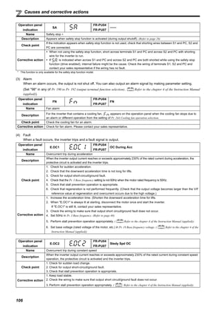
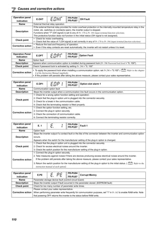
![105
4
TROUBLESHOOTING
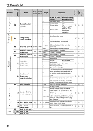
Causes and corrective actions
Operation panel
indication
PS
FR-PU04
FR-PU07
PS
Name PU stop
Description
Stop with of the PU is set in Pr. 75 Reset selection/disconnected PU detection/PU stop selection. (For Pr. 75
refer to the chapter 4 of the Instruction Manual (applied).)
Check point Check for a stop made by pressing of the operation panel.
Corrective action Turn the start signal OFF and release with .
Operation panel
indication
RB
FR-PU04
FR-PU07
RB
Name Regenerative brake prealarm
Description
Appears if the regenerative brake duty reaches or exceeds 85% of the Pr. 70 Special regenerative brake duty value.
When the setting of Pr. 70 Special regenerative brake duty is the initial value (Pr. 70 = "0"), this warning does not occur. If
the regenerative brake duty reaches 100%, a regenerative overvoltage (E. OV_) occurs.
The RBP signal can be simultaneously output with the [RB] display. For the terminal used for the RBP signal output,
assign the function by setting "7 (positive logic) or 107 (negative logic)" in any of Pr. 190 to Pr. 192 (output terminal
function selection). ( Refer to the chapter 4 of the Instruction Manual (applied)).
Check point
1. Check that the brake resistor duty is not high.
2. Check that the Pr. 30 Regenerative function selection and Pr. 70 Special regenerative brake duty settings are correct.
Corrective action
1. Increase the deceleration time.
2. Check that the Pr. 30 Regenerative function selection and Pr. 70 Special regenerative brake duty settings.
Operation panel
indication
TH
FR-PU04
FR-PU07
TH
Name Electronic thermal relay function prealarm
Description
Appears if the cumulative value of the Pr. 9 Electronic thermal O/L relay reaches or exceeds 85% of the preset level. If
it reaches 100% of the Pr. 9 Electronic thermal O/L relay setting, a motor overload trip (E. THM) occurs.
The THP signal can be simultaneously output with the [TH] display. For the terminal used for THP signal output,
assign the function by setting "8 (positive logic) or 108 (negative logic)" in any of Pr. 190 to Pr. 192 (output terminal
function selection). ( Refer to the chapter 4 of the Instruction Manual (applied)).
Check point
1. Check for large load or sudden acceleration.
2. Is the Pr. 9 Electronic thermal O/L relay setting is appropriate? (Refer to page 46)
Corrective action
1. Reduce the load and frequency of operation.
2. Set an appropriate value in Pr. 9 Electronic thermal O/L relay. (Refer to page 46)
Operation panel
indication
MT
FR-PU04 ——
FR-PU07 MT
Name Maintenance signal output
Description
Indicates that the cumulative energization time of the inverter has reached a given time.
When the setting of Pr. 504 Maintenance timer alarm output set time is the initial value (Pr. 504 = "9999"), this warning
does not occur.
Check point
The Pr. 503 Maintenance timer setting is larger than the Pr. 504 Maintenance timer alarm output set time setting.
( Refer to the chapter 4 of the Instruction Manual (applied)).
Corrective action Setting "0" in Pr. 503 Maintenance timer erases the signal.
Operation panel
indication
UV
FR-PU04
FR-PU07
——
Name Undervoltage
Description
If the power supply voltage of the inverter decreases, the control circuit will not perform normal functions. In addition,
the motor torque will be insufficient and/or heat generation will increase. To prevent this, if the power supply voltage
decreases below about 115VAC (about 230VAC for 400V class, about 58VAC for 100V class), this function stops the
inverter output and displays .
An alarm is reset when the voltage returns to normal.
Check point Check that the power supply voltage is normal.
Corrective action Check the power supply system equipment such as power supply.](https://image.slidesharecdn.com/catalog-inverter-fr-e700-instruction-manual-basic-160425090732/85/Catalog-Inverter-FR-E700-instruction-manual-basic-Mitsubishi-Beeteco-com-114-320.jpg)
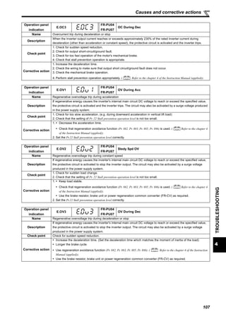
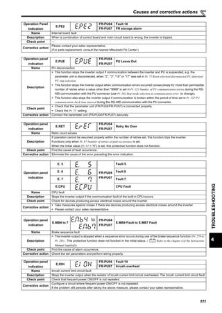
![114
Check and clear of the faults history
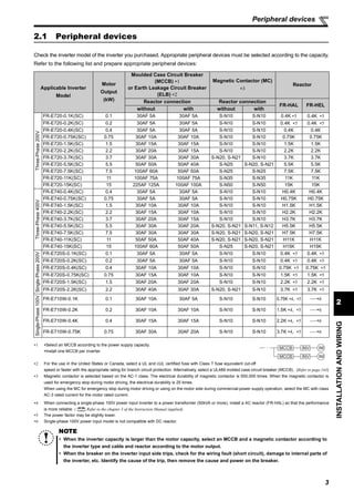
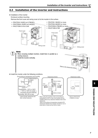
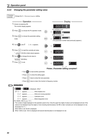
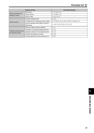
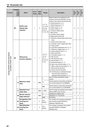
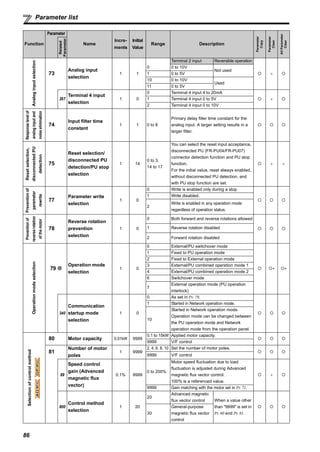
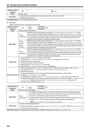
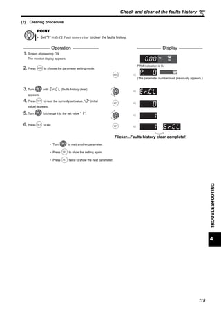
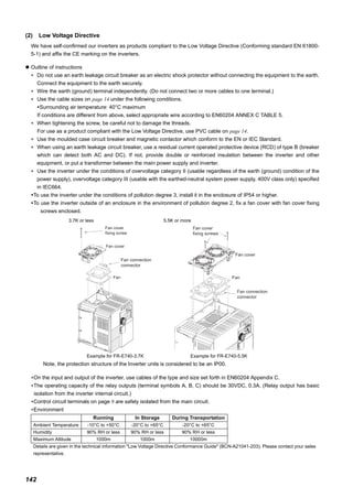
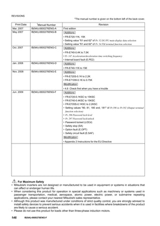
4.5 Check and clear of the faults history
(1) Check for the faults history
∗ The cumulative energization time and actual operation time are accumulated from 0 to 65535 hours, then cleared, and accumulated again from 0.
When the operation panel is used, the time is displayed up to 65.53 (65530h) in the indication of 1h = 0.001, and thereafter, it is added up from 0.
Faults history
Monitor/frequency setting
[Operation panel is
used for operation]
Parameter setting
[Parameter setting change]
[Operation for displaying the faults history]
Eight past faults can be displayed with the setting dial.
(The latest fault is ended by ".".)
When no fault exists, i is displayed.
Flickering
Output frequency Output current
Flickering
Flickering
Flickering
Flickering
Press the
setting dial.
Press the
setting dial.
Press the
setting dial.
Faults history number
(The number of past faults is displayed.)
Hz
A
Output voltage
Flickering
Energization time ∗
Flickering](https://image.slidesharecdn.com/catalog-inverter-fr-e700-instruction-manual-basic-160425090732/85/Catalog-Inverter-FR-E700-instruction-manual-basic-Mitsubishi-Beeteco-com-123-320.jpg)


This document provides instructions for installing and operating Mitsubishi FR-E700 series inverters. It begins with product checking and identification of parts. Section 2 provides details on installation and wiring, including peripheral devices, removing covers, proper mounting, terminal connections and wiring diagrams. Section 3 covers driving the motor, including operation panel functions, monitoring output, starting and stopping in PU and external operation modes, and parameter lists. Section 4 is troubleshooting, with lists of faults, causes and remedies. Section 5 covers maintenance and inspections. Section 6 provides product specifications and outlines.


