Download to read offline


![Contents
FR-E700 EC XI
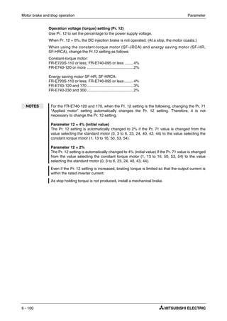
6.9 Motor brake and stop operation . . . . . . . . . . . . . . . . . . . . . . . . . . . . . . . . . . . .6-98
6.9.1 DC injection brake (Pr. 10 to Pr. 12) . . . . . . . . . . . . . . . . . . . . . . . . . .6-98
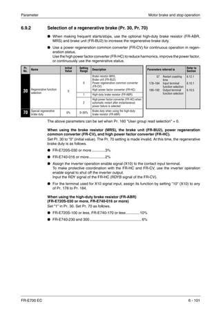
6.9.2 Selection of a regenerative brake (Pr. 30, Pr. 70). . . . . . . . . . . . . . .6-101
6.9.3 Stop selection (Pr. 250). . . . . . . . . . . . . . . . . . . . . . . . . . . . . . . . . . .6-103
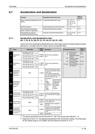
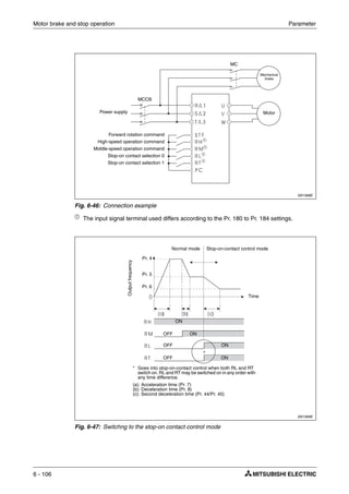
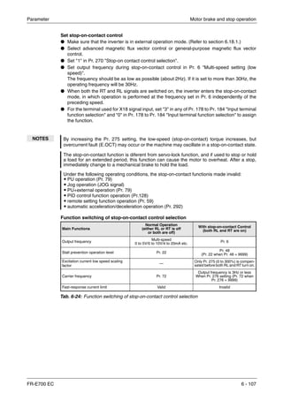
6.9.4 Stop-on contact control function
(Pr. 6, Pr. 48, Pr. 270, Pr. 275, Pr. 276) . . . . . . . . . . . . . . . . . . . . . .6-105
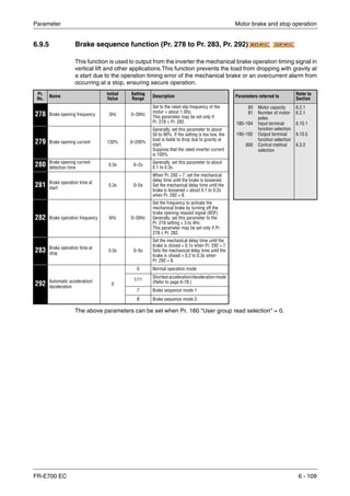
6.9.5 Brake sequence function (Pr. 278 to Pr. 283, Pr. 292) . . . . . . . . . .6-109
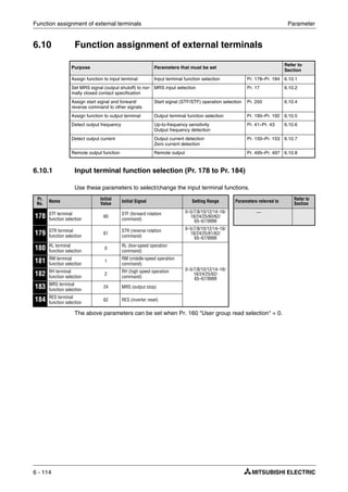
6.10 Function assignment of external terminals. . . . . . . . . . . . . . . . . . . . . . . . . . .6-114
6.10.1 Input terminal function selection (Pr. 178 to Pr. 184) . . . . . . . . . . . .6-114
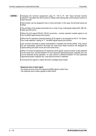
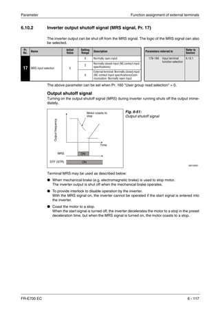
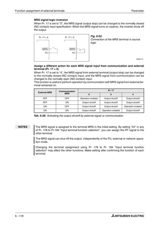
6.10.2 Inverter output shutoff signal (MRS signal, Pr. 17) . . . . . . . . . . . . . .6-117
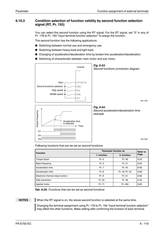
6.10.3 Condition selection of function validity by second
function selection signal (RT, Pr. 155) . . . . . . . . . . . . . . . . . . . . . . .6-119
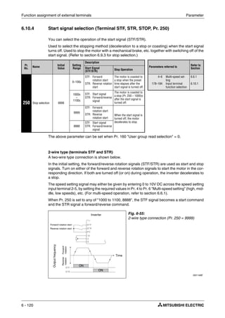
6.10.4 Start signal selection (Terminal STF, STR, STOP, Pr. 250) . . . . . . .6-120
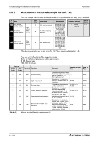
6.10.5 Output terminal function selection (Pr. 190 to Pr. 192) . . . . . . . . . . .6-124
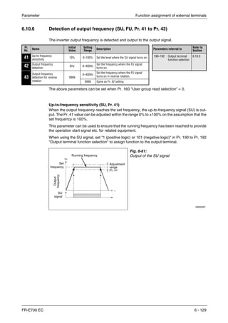
6.10.6 Detection of output frequency (SU, FU, Pr. 41 to Pr. 43) . . . . . . . . .6-129
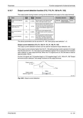
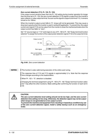
6.10.7 Output current detection function (Y12, Y13, Pr. 150 to Pr. 153) . . .6-131
6.10.8 Remote output function (REM, Pr. 495 to Pr. 497) . . . . . . . . . . . . . .6-133
6.11 Monitor display and monitor output signals . . . . . . . . . . . . . . . . . . . . . . . . . .6-136
6.11.1 Speed display and speed setting (Pr. 37) . . . . . . . . . . . . . . . . . . . . .6-136
6.11.2 Monitor display selection of DU/PU and terminal AM
(Pr. 52, Pr. 158, Pr. 170, Pr. 171, Pr. 268, Pr. 563, Pr. 564). . . . . . .6-138
6.11.3 Reference of the terminal AM (analog voltage output)
(Pr. 55, Pr. 56). . . . . . . . . . . . . . . . . . . . . . . . . . . . . . . . . . . . . . . . . .6-146
6.11.4 Terminal AM calibration [calibration parameter
Pr. 645, C1 (Pr.901)] . . . . . . . . . . . . . . . . . . . . . . . . . . . . . . . . . . . . .6-148
6.12 Operation selection at power failure. . . . . . . . . . . . . . . . . . . . . . . . . . . . . . . .6-151
6.12.1 Automatic restart
(Pr. 30, Pr. 57, Pr. 58, Pr. 96, Pr. 162, Pr. 165,
Pr. 298, Pr. 299, Pr. 611) . . . . . . . . . . . . . . . . . . . . . . . . . . . . . . . . .6-151
6.12.2 Power failure-time deceleration-to-stop function (Pr. 261) . . . . . . . .6-162
6.13 Operation setting at alarm occurrence . . . . . . . . . . . . . . . . . . . . . . . . . . . . . .6-166
6.13.1 Retry function (Pr. 65, Pr. 67 to Pr. 69). . . . . . . . . . . . . . . . . . . . . . .6-166
6.13.2 Input/output phase failure protection selection (Pr. 251, Pr. 872) . . .6-169
6.13.3 Earth (ground) fault detection at start (Pr. 249). . . . . . . . . . . . . . . . .6-170
6.14 Energy saving operation. . . . . . . . . . . . . . . . . . . . . . . . . . . . . . . . . . . . . . . . .6-171
6.14.1 Optimum excitation control (Pr. 60) . . . . . . . . . . . . . . . . . . . . . . . . .6-171
6.15 Motor noise, EMI measures, mechanical resonance . . . . . . . . . . . . . . . . . . .6-172
6.15.1 PWM carrier frequency and soft-PWM control (Pr. 72, Pr. 240) . . . .6-172
6.15.2 Speed smoothing control (Pr. 653) . . . . . . . . . . . . . . . . . . . . . . . . . .6-173](https://image.slidesharecdn.com/fr-e700-140613033232-phpapp01/85/Fr-e700-15-320.jpg)
![Contents
XII
6.16 Frequency setting by analog input (terminal 2, 4) . . . . . . . . . . . . . . . . . . . . .6-174
6.16.1 Analog input selection (Pr. 73, Pr. 267) . . . . . . . . . . . . . . . . . . . . . .6-174
6.16.2 Input filter time constant (Pr. 74) . . . . . . . . . . . . . . . . . . . . . . . . . . . .6-179
6.16.3 Bias and gain of frequency setting voltage (current)
[Pr. 125, Pr. 126, Pr. 241, C2 (Pr. 902) to C7 (Pr. 905)] . . . . . . . . . .6-180
6.17 Misoperation prevention and parameter setting restriction. . . . . . . . . . . . . . .6-187
6.17.1 Reset selection/disconnected PU detection/PU stop selection
(Pr. 75) . . . . . . . . . . . . . . . . . . . . . . . . . . . . . . . . . . . . . . . . . . . . . . .6-187
6.17.2 Parameter write selection (Pr. 77). . . . . . . . . . . . . . . . . . . . . . . . . . .6-192
6.17.3 Reverse rotation prevention selection (Pr. 78) . . . . . . . . . . . . . . . . .6-194
6.17.4 User groups (Pr. 160, Pr. 172 to Pr. 174) . . . . . . . . . . . . . . . . . . . . .6-195
6.18 Selection of operation mode and operation location . . . . . . . . . . . . . . . . . . .6-198
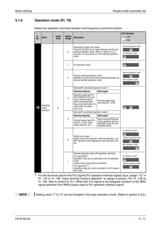
6.18.1 Operation mode selection (Pr. 79) . . . . . . . . . . . . . . . . . . . . . . . . . .6-198
6.18.2 Operation mode at power on (Pr. 79, Pr. 340) . . . . . . . . . . . . . . . . .6-210
6.18.3 Start command source and frequency command source during
communication operation
(Pr. 338, Pr. 339, Pr. 550, Pr. 551) . . . . . . . . . . . . . . . . . . . . . . . . . .6-212
6.19 Communication operation and setting . . . . . . . . . . . . . . . . . . . . . . . . . . . . . .6-221
6.19.1 PU connector . . . . . . . . . . . . . . . . . . . . . . . . . . . . . . . . . . . . . . . . . .6-221
6.19.2 Initial settings and specifications of RS-485 communication
(Pr. 117 to Pr. 120, Pr. 123, Pr. 124, Pr. 549). . . . . . . . . . . . . . . . . .6-226
6.19.3 Communication E²PROM write selection (Pr. 342) . . . . . . . . . . . . . .6-232
6.19.4 Mitsubishi inverter protocol (computer link communication) . . . . . . .6-233
6.19.5 Modbus-RTU communication
(Pr. 117, Pr. 118, Pr. 120, Pr. 122, Pr. 343, Pr. 549) . . . . . . . . . . . .6-251
6.19.6 USB communication (Pr. 547, Pr. 548) . . . . . . . . . . . . . . . . . . . . . . .6-269
6.20 Special operation . . . . . . . . . . . . . . . . . . . . . . . . . . . . . . . . . . . . . . . . . . . . . .6-270
6.20.1 PID control (Pr. 127 to Pr. 134). . . . . . . . . . . . . . . . . . . . . . . . . . . . .6-270
6.20.2 Dancer control (Pr. 44, Pr. 45, Pr. 128 to Pr. 134) . . . . . . . . . . . . . .6-282
6.20.3 Droop control (Pr. 286 to Pr. 287) . . . . . . . . . . . . . . . . . . . . . . . . . .6-291
6.20.4 Regeneration avoidance function
(Pr. 665, Pr. 882, Pr. 883, Pr. 885, Pr. 886) . . . . . . . . . . . . . . . . . . .6-292
6.21 Useful functions . . . . . . . . . . . . . . . . . . . . . . . . . . . . . . . . . . . . . . . . . . . . . . .6-295
6.21.1 Cooling fan operation selection (Pr. 244) . . . . . . . . . . . . . . . . . . . . .6-295
6.21.2 Display of the life of the inverter parts (Pr. 255 to Pr. 259) . . . . . . . .6-296
6.21.3 Maintenance timer alarm (Pr. 503, Pr. 504) . . . . . . . . . . . . . . . . . . .6-300
6.21.4 Current average value monitor signal (Pr. 555 to Pr. 557) . . . . . . . .6-301
6.21.5 Free parameters (Pr. 888, Pr. 889) . . . . . . . . . . . . . . . . . . . . . . . . . .6-305](https://image.slidesharecdn.com/fr-e700-140613033232-phpapp01/85/Fr-e700-16-320.jpg)
![Product checking and part identification Description of the Case
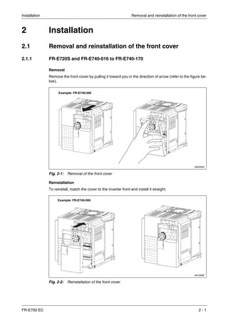
FR-E700 EC 1 - 3
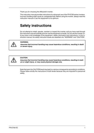
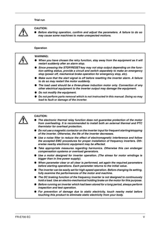
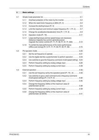
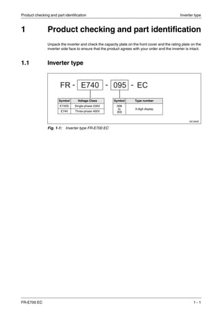
1.2.1 Accessory
Fan cover fixing screws
Capacity Screw Size [mm] Number
FR-E720S-050 to 110 M3 × 35 1
FR-E740-040 to 095 M3 × 35 1
FR-E740-120 to 300 M3 × 35 2
Tab. 1-1: Fan cover fixing screws
NOTES The fan cover fixing screws are not delivered with models FR-E720S-008 to 030 and
FR-E740-026 or less.
For removal and reinstallation of the cooling fans, refer to section 8.1.7.](https://image.slidesharecdn.com/fr-e700-140613033232-phpapp01/85/Fr-e700-21-320.jpg)

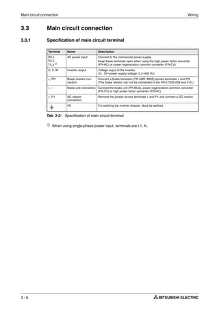
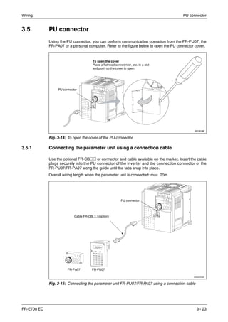
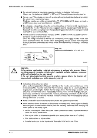
![Wiring Inverter and peripheral devices
FR-E700 EC 3 - 3
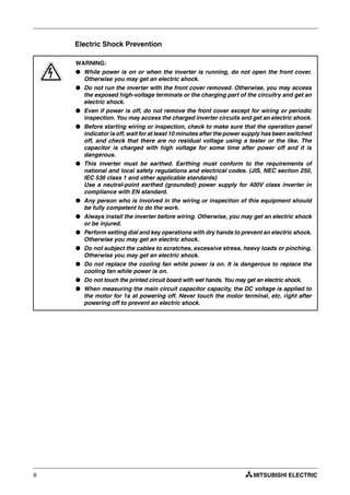
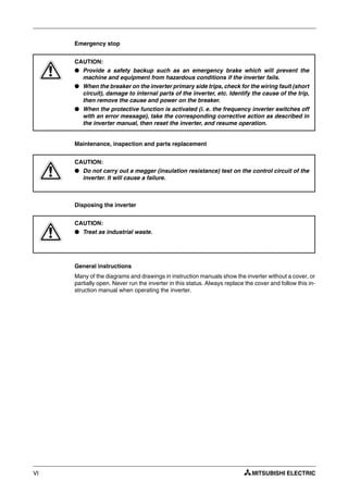
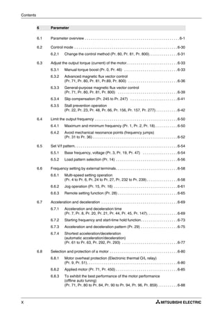
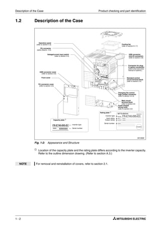
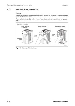
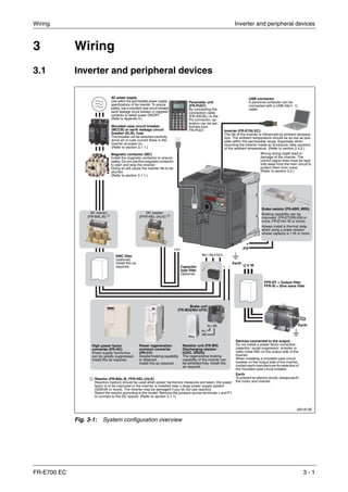
3.1.1 Peripheral devices
Check the motor capacity of the inverter you purchased. Appropriate peripheral devices must be
selected according to the capacity. Refer to the following list and prepare appropriate peripheral
devices:
ቢ
Select the MCCB according to the inverter power supply capacity. Install one MCCB per
inverter.
The places with "xx" refer to the breaking capacity in case of short circuit. The correct
selection must be done depending on the design of the power input wiring.
ባ
Magnetic contactor is selected based on the AC-1 class. The electrical durability of magnetic
contactor is 500,000 times. When the magnetic contactor is used for emergency stop during
motor driving, the electrical durability is 25 times.
When using the MC for emergency stop during motor driving or using on the motor side
during commercial-power supply operation, select the MC with class AC-3 rated current for
the motor rated current.
Motor output [kW] Applicable Inverter Type
Breaker Selection ቢ Input Side Magnetic
Contactor ባ
Reactor connection Reactor connection
Without With Without With
200Vclass
0.1 FR-E720S-008
NF32 xx 3P 5 A
S-N10
0.2 FR-E720S-015
0.4 FR-E720S-030 NF32 xx 3P 10 A
0.75 FR-E720S-050 NF32 xx 3P 15 A NF32 xx 3P 10 A
1.5 FR-E720S-080 NF63 xx 3P 20 A
2.2 FR-E720S-110 NF32 xx 3P 40 A NF32 xx 3P 32 A S-N20, S-N21 S-N10
400Vclass
0.4 FR-E740-016
NF32 xx 3P 5 A
S-N10
0.75 FR-E740-026
1.5 FR-E740-040 NF32 xx 3P 10 A
2.2 FR-E740-060 NF32 xx 3P 15 A NF32 xx 3P 10 A
3.7 FR-E740-095 NF63 xx 3P 20 A NF32 xx 3P 15 A
5.5 FR-E740-120 NF63 xx 3P 30 A NF63 xx 3P 20 A S-N20 S-N11
7.5 FR-E740-170 NF63 xx 3P 30 A NF63 xx 3P 30 A
S-N20
11 FR-E740-230 NF63 xx 3P 50 A NF63 xx 3P 40 A
15 FR-E740-300 NF125 xx 3P 100 A NF63 xx 3P 50 A S-N25 S-N20
Tab. 3-1: Breakers and contactors
Fig. 3-2:
Installation of the breakers
I001332E
NOTES When the inverter capacity is larger than the motor capacity, select an MCCB and a mag-
netic contactor according to the inverter type and cable and reactor according to the motor
output.
When the breaker on the inverter primary side trips, check for the wiring fault (short circuit),
damage to internal parts of the inverter, etc. Identify the cause of the trip, then remove the
cause and power on the breaker.
M
3~
M
3~
Inverter
MCCB Inverter
MCCB](https://image.slidesharecdn.com/fr-e700-140613033232-phpapp01/85/Fr-e700-37-320.jpg)
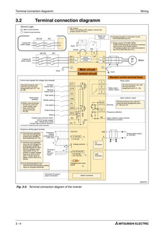
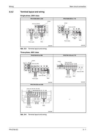
![Wiring Main circuit connection
FR-E700 EC 3 - 9
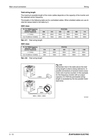
Cables and wiring length
Select the recommended cable size to ensure that a voltage drop will be 2% max.
If the wiring distance is long between the inverter and motor, a main circuit cable voltage drop
will cause the motor torque to decrease especially at the output of a low frequency.
The following tables indicate a selection example for the wiring length of 20m.
200V class (when input power supply is 230V)
400V class (when input power supply is 440V)
ቢ
The recommended cable size is that of the HIV cable (600 V class 2 vinyl-insulated cable)
with continuous maximum permissible temperature of 75 °C. Assumes that the ambient
temperature is 50 °C or less and the wiring distance is 20 m or less.
ባ
The recommended cable size is that of the THHW cable with continuous maximum
permissible temperature of 75 °C. Assumes that the ambient temperature is 40 °C or less
and the wiring distance is 20 m or less.
(Selection example for use mainly in the United States.)
ቤ The recommended cable size is that of the PVC cable with continuous maximum permissible
temperature of 70°C. Assumes that the ambient temperature is 40°C or less and the wiring
distance is 20m or less.
(Selection example for use mainly in Europe.)
ብ
The terminal screw size indicates the terminal size for R/L1, S/L2, T/L3, U, V, W, and a screw
for earthing. (For single-phase power input, the terminal screw size indicates the size of
terminal screw for L1, N, U, V, W, PR, +, – and P1 and a screw for earthing (grounding).)
The line voltage drop can be calculated by the following expression:
Use a larger diameter cable when the wiring distance is long or when it is desired to decrease
the voltage drop (torque reduction) in the low speed range.
Applicable Inverter
Type
Terminal
Screw
Size ብ
Tightening
Torque
[Nm]
Crimping
Terminal
Cable Size
HIV etc. [mm²] ቢ
AWG ባ
PVC [mm²] ቤ
L1, N,
P1, +
U, V,
W
L1, N,
P1, +
U, V,
W
Earth
cable
gauge
L1, N,
P1, +
U, V,
W
L1, N,
P1, +
U, V,
W
Earth
cable
gauge
FR-E720S-008 to 030 M3.5 1.2 2-3.5 2-3.5 2 2 2 14 14 2.5 2.5 2.5
FR-E720S-050 M4 1.5 2-4 2-4 2 2 2 14 14 2.5 2.5 2.5
FR-E720S-080 M4 1.5 2-4 2-4 2 2 2 14 14 2.5 2.5 2.5
FR-E720S-110 M4 1.5 5.5-4 2-4 3.5 2 3.5 12 14 4 2.5 4
Tab. 3-5: Cable size
Applicable Inverter
Type
Terminal
Screw
Size ብ
Tightening
Torque
[Nm]
Crimping
Terminal
Cable Size
HIV etc. [mm²] ቢ AWG ባ PVC [mm²] ቤ
R/L1,
S/L2
T/L3,
P1, +
U, V,
W
R/L1,
S/L2
T/L3,
P1, +
U, V,
W
Earth
cable
gauge
R/L1,
S/L2
T/L3,
P1, +
U, V,
W
R/L1,
S/L2
T/L3,
P1, +
U, V,
W
Earth
cable
gauge
FR-E740-016 to 095 M4 1.5 2-4 2-4 2 2 2 14 14 2.5 2.5 2.5
FR-E740-120 M4 1.5 5.5-4 2-4 3.5 2 3.5 12 14 4 2.5 4
FR-E740-170 M4 1.5 5.5-4 5.5-4 3.5 3.5 3.5 12 12 4 4 4
FR-E740-230 M4 1.5 5.5-4 5.5-4 5.5 5.5 8 10 10 6 6 10
FR-E740-300 M5 2.5 8-5 8-5 8 8 8 8 8 10 10 10
Tab. 3-6: Cable size
Line voltage drop [V]
3 wire restistance [mΩ/m]× wiring distance [m]× current [A]×
1000
-------------------------------------------------------------------------------------------------------------------------------------------------------------------------=](https://image.slidesharecdn.com/fr-e700-140613033232-phpapp01/85/Fr-e700-43-320.jpg)
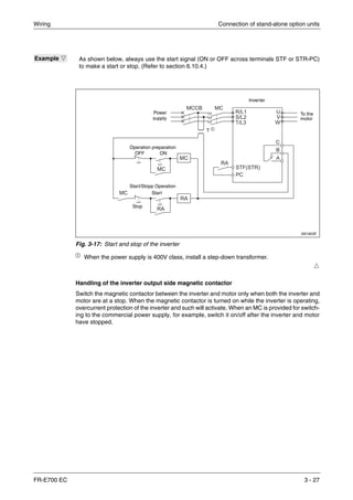

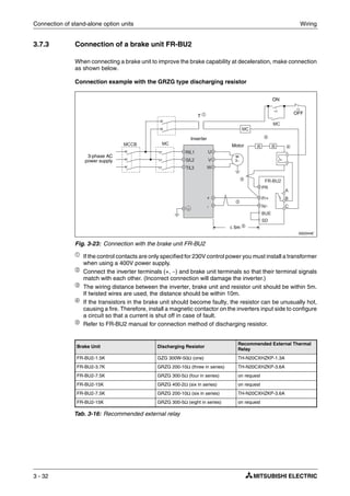
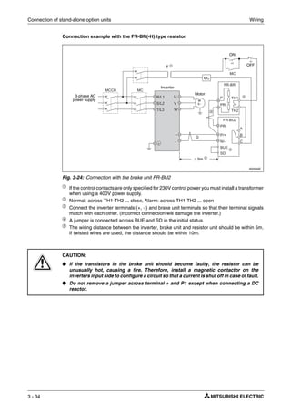
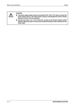
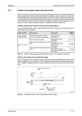
![Wiring Connection of stand-alone option units
FR-E700 EC 3 - 37
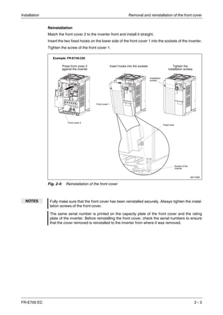
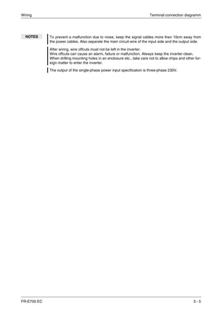
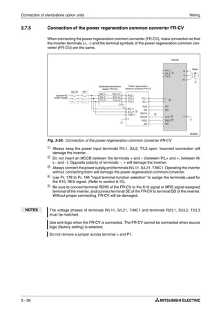
3.7.6 Connection of the power improving DC reactor FFR-HEL-(H)-E
When using the DC reactor (FFR-HEL-(H)-E), connect it between terminals P1 and +. In this
case, the jumper connected across terminals P1 and + must be removed. Otherwise, the reactor
will not exhibit its performance.
3.7.7 Installation of a reactor
When the inverter is connected near a large-capacity power transformer (500kVA or more) or
when a power capacitor is to be switched over, an excessive peak current may flow in the power
input circuit, damaging the converter circuit. To prevent this, always install the optional DC re-
actor (FFR-HEL-(H)-E) or AC reactor (FR-BAL-B).
ቢ
When connecting the FFR-HEL-(H)-E, remove the jumper across terminals + and P1.
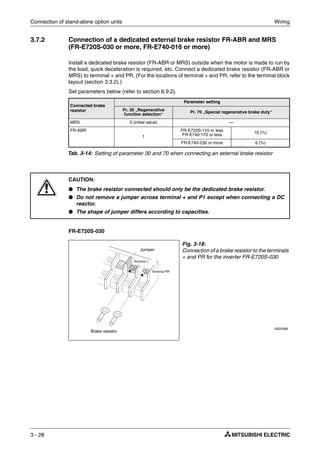
Fig. 3-27:
Connection of a DC reactor
I002048E_N
NOTES The wiring distance should be within 5m.
The size of the cables used should be equal to or larger than that of the power supply cables
(R/L1, S/L2, T/L3).
I002038E
Fig. 3-28: Installation of a reactor
NOTES
The wiring length between the FFR-HEL-(H)-E and inverter should be 5m maximum and
minimized.
Use the same wire size as that of the power supply wire (R/L1, S/L2, T/L3). (Refer to page 3-9.)
FFR-HEL-(H)-E
Remove the
jumper.
Power
supply
AC reactor
(FR-BAL-B)
DC reactor
(FFR-HEL-(H)-E) ቢ
Installation
range of reactor
Wiring length [m]
Powersupply
capacity[kVA]
M
3~
Inverter
DC reactor
(FFR-HEL-(H)-E) ቢ
Single-phase power input
Three-phase power input
Power
supply
AC reactor
(FR-BAL-B)
Inverter
M
3~](https://image.slidesharecdn.com/fr-e700-140613033232-phpapp01/85/Fr-e700-71-320.jpg)
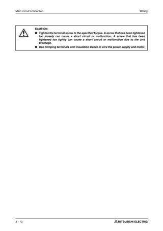
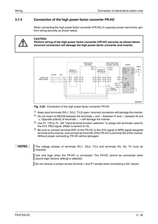
![Wiring Electromagnetic compatibility (EMC)
FR-E700 EC 3 - 39
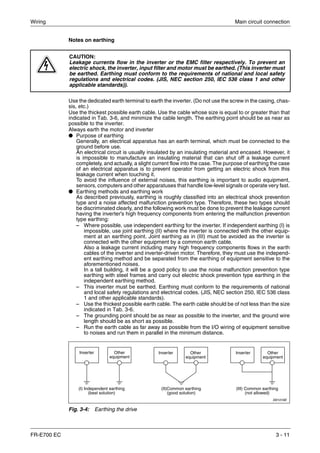
Ħ
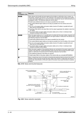
● Countermeasures
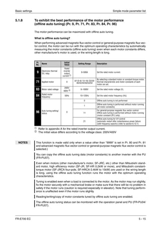
– Use Pr. 9 "Electronic thermal O/L relay".
– If the carrier frequency setting is high, decrease the Pr. 72 "PWM frequency selection"
setting. Note that motor noise increases. Selecting Pr. 240 "Soft-PWM operation selec-
tion" makes the sound inoffensive. To ensure that the motor is protected against line-to-
line leakage currents, it is recommended to use a temperature sensor (e.g. PTC element)
to directly detect motor temperature.
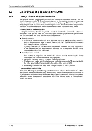
● Selecting a power supply circuit breaker:
You can also use a circuit breaker (MCCB) to protect the power supply lines against short
circuits and overloads. However, note that this does not protect the inverter (rectifiers, IGBT).
Select the capacity of the circuit breaker on the basis of the cross-sectional area of the power
supply lines. To calculate the required mains current trip point you need to know the power
required by the inverter (Refer to Rated Input Capacity in Appendix A, Specifications) and
the mains supply voltage. Select a circuit breaker with a trip point that is slightly higher than
calculated, particularly in the case of breakers with electromagnetic tripping, since the trip
characteristics are strongly influenced by the harmonics in the power supply line.
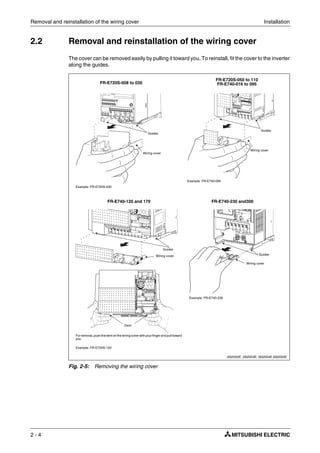
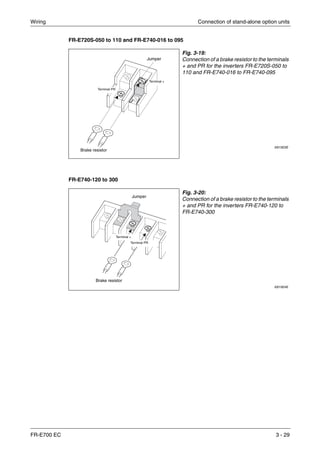
Example Ĥ Line-to-line leakage current data example
Dedicated motor: SF-JR 4P
Carrier frequency: 14.5kHz
Used wire: 2mm², 4 cores, cab tyre cable
Motor Capacity [kW] Rated Motor Current [A]
Leakage Currents [mA]
Wiring length 50m Wiring length 100m
0.4 1.1 620 1000
0.75 1.9 680 1060
1.5 3.5 740 1120
2.2 4.1 800 1180
3.7 6.4 880 1260
5.5 9.7 980 1360
7.5 12.8 1070 1450
Tab. 3-17: Line-to-line leakage current data example
I001043E
Fig. 3-29: Line-to-line leakage currents
NOTE The earth leakage breaker must be either a Mitsubishi earth leakage breaker (ELB, for har-
monics and surges) or an ELB with breaker designed for harmonic and surge suppression
that is approved for use with frequency inverters.
Power
supply
Inverter
Line-to-line
leakage currents
path
Line-to-line static
capacitances
M
3~
Thermal
relay
Motor](https://image.slidesharecdn.com/fr-e700-140613033232-phpapp01/85/Fr-e700-73-320.jpg)
![Electromagnetic compatibility (EMC) Wiring
3 - 40
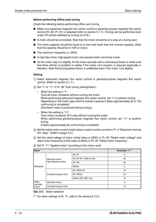
Note on selecting a suitable power supply ELCB
If you install a Mitsubishi frequency inverter with a 3-phase power supply in locations where an
earth leakage contact breaker is required by the VDE you must install a universal-current sen-
sitive ELCB conforming to the specifications laid down in VDE 0160 / EN 50178 (ELCB Type B).
This is necessary because pulse-current sensitive ELCBs (Type A) do not pro-vide reliable trip-
ping performance for the frequency inverter in response to DC leakage current.
When selecting a suitable universal-current sensitive ELCB you must also take into account the
influence of the mains filter, the length of the shielded motor power cables and the frequency on
the leakage currents.
Also note that when the mains power is switched on with switches without a snap-action function
the resulting brief asymmetrical load can cause unwanted triggering of the ELCB.
This problem can be avoided by using a Type B ELCB with a delayed response function, or by
using a contactor relay to switch all three phases simultaneously.
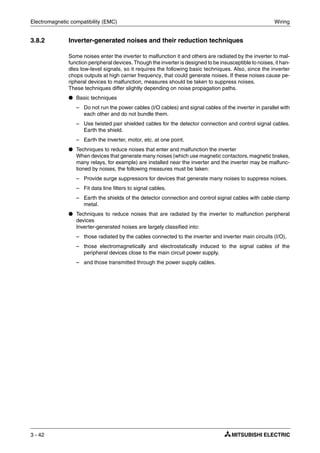
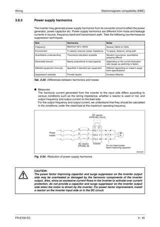
Calculate the trip current sensitivity of the ELB as follows:
● Breaker designed for harmonic and surge suppression:
IΔn ≥ 10 × (Ig1 + Ign + Igi + lg2 + lgm)
● Standard breaker:
IΔn ≥ 10 × [Ig1 + Ign + Igi + 3 × (Ig2 + lgm)]
Ig1, Ig2: Leakage currents in wire path during commercial power supply operation
Ign: Leakage current of inverter input side noise filter
Igm: Leakage current of motor during commercial power supply operation
Igi: Leakage current of inverter unit
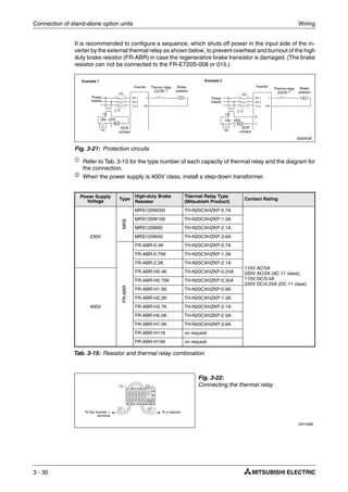
I002037E
Fig. 3-30: Leakage currents
NOTE For star connection, the amount of leakage current is 1/3.
Example of leakage current per 1km
during the commercial power supply
operation when the CV cable is
routed in metal conduit
200V/60Hz)
Leakage current example of 3-phase
induction motor during the
commercial power supply operation
(200V/60Hz)
Power supply size [mm²] Motor capacity [kW]
Leakagecurrent[mA]
Leakagecurrent[mA]
Example of leakage current per 1km
during the commercial power supply
operation when the CV cable is
routed in metal conduit
(Three-phase three-wire delta
connection 400V/60Hz)
Leakage current example of 3-
phase induction motor during the
commercial power supply
operation
(Totally-enclosed fan-cooled type
motor 400V/60Hz)
Leakagecurrent[mA]
Leakagecurrent[mA]
Power supply size [mm²] Motor capacity [kW]](https://image.slidesharecdn.com/fr-e700-140613033232-phpapp01/85/Fr-e700-74-320.jpg)
![Wiring Electromagnetic compatibility (EMC)
FR-E700 EC 3 - 41
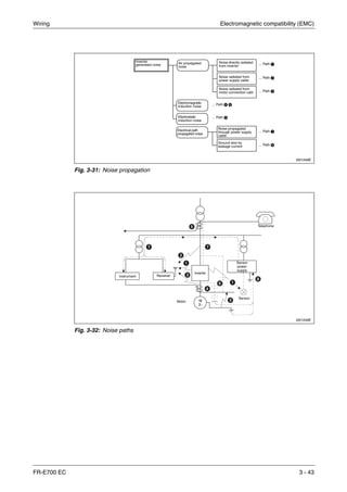
Ħ
Example Ĥ
Breaker Designed for Harmonic
and Surge Suppression
Standard Breaker
Leakage current Ig1 [mA]
Leakage current Ign [mA] 0 (without noise filter)
Leakage current Igi [mA] 1 (with noise filter)
Leakage current Ig2 [mA]
Motor leakage current Igm [mA] 0.36
Total leakage current [mA] 2.79 6.15
Rated sensivity current [mA] 30 100
Tab. 3-18: Estimation of the permanent flowing leakage current
NOTES The frequency inverter monitors its own output for ground faults up to a frequency of 120Hz.
However, it is important to understand that this feature only protects the inverter itself. It can-
not be used to provide protection against shock hazards for personnel.
In the connection earthed-neutral system, the sensitivity current is purified against an earth
fault in the inverter output side. Earthing must conform to the requirements of national and
local safety regulations and electrical codes. (JIS, NEC section 250, IEC 536 class 1 and
other applicable standards)
When the breaker is installed on the output side of the inverter, it may be unnecessarily
operated by harmonics even if the effective value is less than the rating. In this case, do not
install the breaker since the eddy current and hysteresis loss will increase, leading to tem-
perature rise.
The following models are standard breakers: BV-C1, BC-V, NVB, NV-L, NV-G2N, NV-G3NA
and NV-2F earth leakage relay (except NV-ZHA), NV with AA neutral wire open-phase pro-
tection.
The other models are designed for harmonic and surge suppression: NV-C/NV-S/MN series,
NV30-FA, NV50-FA, BV-C2, earth leakage alarm breaker (NF-Z), NV-ZHA, NV-H
3
Inverter M
3~ 3~, 400V, 2.2kW
ELB
5.5mm² × 5m 5.5mm² × 60m
Ig1 Ign
Igi
Ig2 Igm
Noise filter
(optional)
1
3
--- 66×
5 m
1000 m
--------------------× 0.11=
1
3
--- 66×
60 m
1000 m
--------------------× 1,32=](https://image.slidesharecdn.com/fr-e700-140613033232-phpapp01/85/Fr-e700-75-320.jpg)
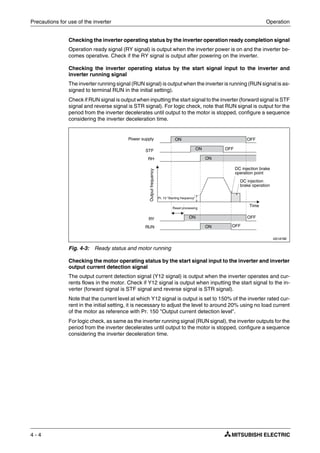
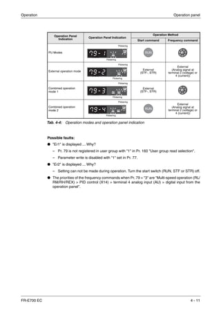
![Drive the motor Operation
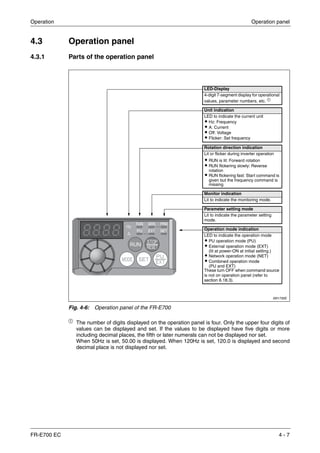
4 - 6
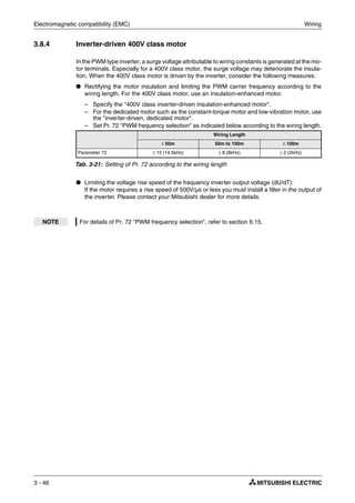
4.2 Drive the motor
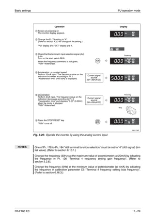
The inverter needs frequency command and start command. Refer to the flow chart below to
perform setting.
Check the following items before powering on the inverter:
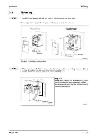
● Check that the inverter is installed correctly in a correct place. (Refer to section 2.3.)
● Check that wiring is correct. (Refer to section 3.2.)
● Check that no load is connected to the motor.
I001732E
Fig. 4-5: Steps of operation
NOTES When protecting the motor from overheat by the inverter, set Pr. 9 "Electronic thermal O/L
relay". (Refer to section 5.1.1.)
When the rated frequency of the motor is 60Hz, set Pr. 3 "Base frequency" (Refer to
section 5.1.2.)
Step of operation
Installation/mounting
Wiring of the power
supply and motor
System examination
How
to give a start
command?
Start command using the PU connector and plug-in
option (communication). (Refer to section 3.5.2.)
Start command with
RUN on the operation
panel (PU).
How to
give a frequency
command?
Connect a switch, relay, etc. to the
control circuit terminal block of the
inverter to give a start command.
(External)
How to
give a frequency
command?
Set from the operation
panel and the PU
(FR-PU04/FR-PU07).
(PU) (PU)/(External) (PU)/(External) (PU)/(External)
Change frequency with
ON/OFF switches
connected to terminals
(multi-speed setting).
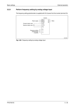
Perform frequency setting by
a voltage output device
(connection across terminals
2-5).
Perform frequency setting by
a current output device
(connection across
terminals 4-5).
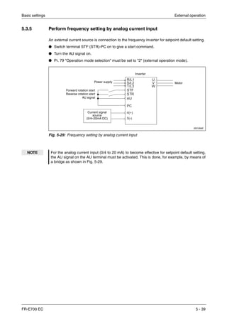
(Refer to page 5-20) (Refer to page 5-24) (Refer to page 5-26) (Refer to page 5-28)
Set from the operation
panel and the PU
(FR-PU04/FR-PU07).
(PU)/(External) (External) (External) (External)
Change frequency with
ON/OFF switches
connected to terminals
(multi-speed setting).
Perform frequency setting by
a voltage output device
(connectionacrossterminals
2-5).
Perform frequency setting by
a current output device
(connection across
terminals 4-5).
(Refer to page 5-30) (Refer to page 5-32) (Refer to page 5-35) (Refer to page 5-39)
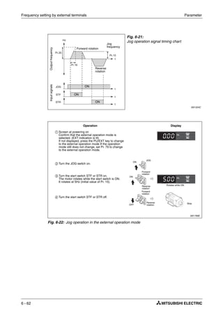
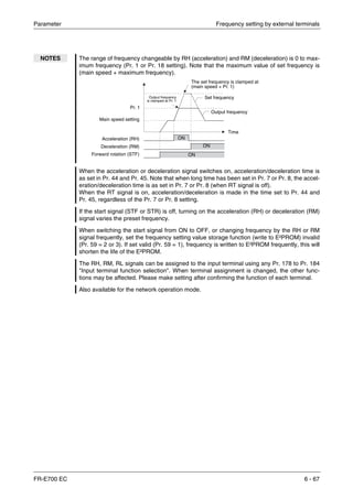
RUN
Frequency [Hz]
Time [s]
ONStart command
Frequency command
Output
frequency](https://image.slidesharecdn.com/fr-e700-140613033232-phpapp01/85/Fr-e700-86-320.jpg)
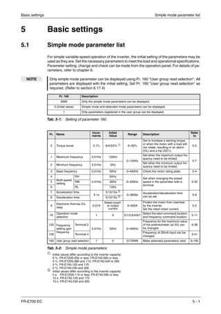
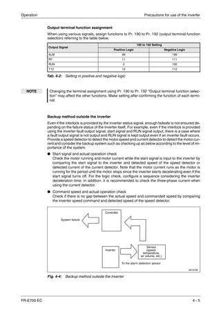
![Basic settings Simple mode parameter list
FR-E700 EC 5 - 5
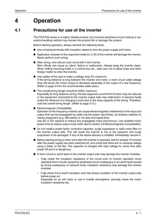
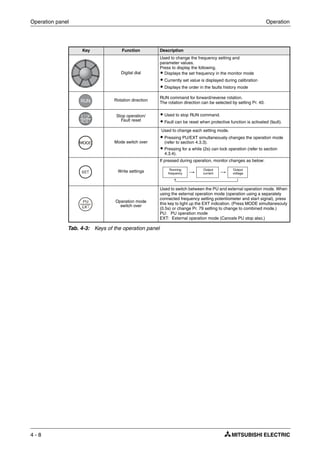
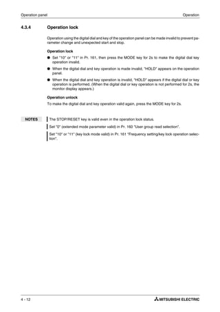
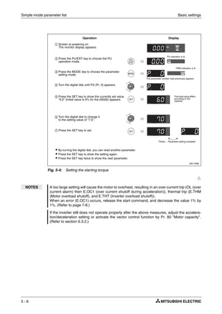
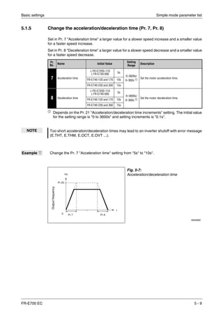
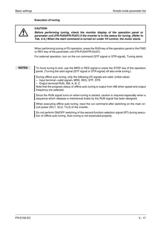
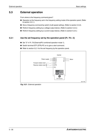
5.1.3 Increase the starting torque (Pr. 0)
Set this parameter when the motor with a load does not rotate, an alarm OL is output, resulting
in an inverter trip due to OC1, etc.
Pr.
No.
Name Initial Value Setting
Range
Description
0 Torque boost
FR-E720S-008 to 050
FR-E740-016 and 026 6%
0–30%
Motor torque in the low-frequency range can be
adjusted to the load to increase the starting motor
torque.
FR-E720S-080 and 110
FR-E740-040 to 095
4%
FR-E740-120 and 170 3%
FR-E740-230 and 300 2%
Example Ĥ When the motor with a load does not rotate, increase the Pr. 0 value 1% by 1% unit by look-
ing at the motor movement. (The guideline is for about 10% change at the greatest.)
Fig. 5-3:
Relation between output frequency and output
voltage
I001098E
V/FV/FV/F
Setting
range
Pr. 0, Pr. 46
Outputvoltage
Base
frequency
Output frequency [Hz]](https://image.slidesharecdn.com/fr-e700-140613033232-phpapp01/85/Fr-e700-103-320.jpg)
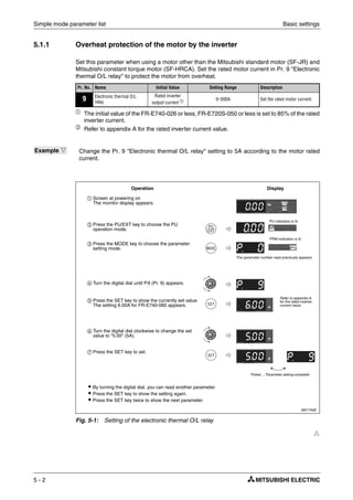
![Basic settings Simple mode parameter list
FR-E700 EC 5 - 7
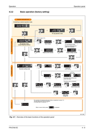
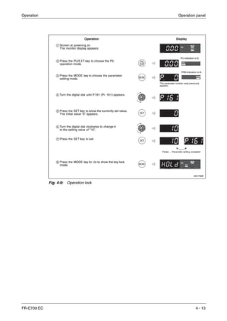
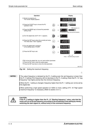
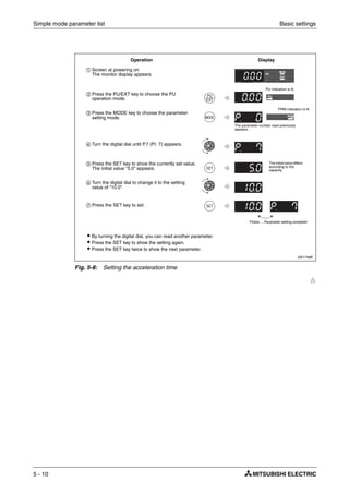
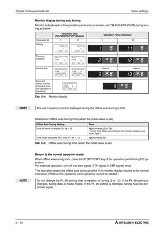
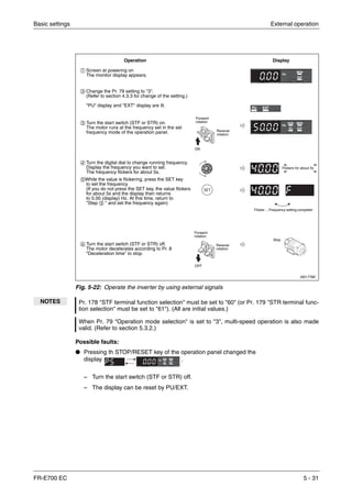
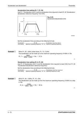
5.1.4 Limit the maximum and minimum output frequency (Pr. 1, Pr. 2)
Pr.
No. Name Initial Value
Setting
Range
Description
1 Maximum frequency 120Hz 0–120Hz Set the upper limit of the output frequency.
2 Minimum frequency 0Hz 0–120Hz Set the lower limit of the output frequency.
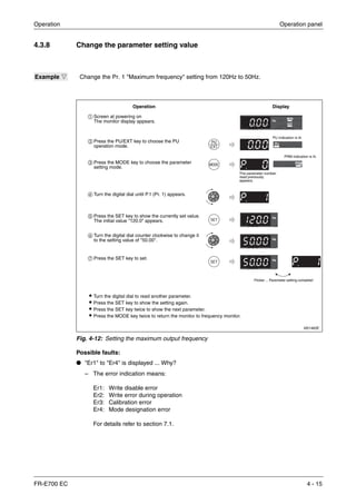
Example Ĥ You can limit the motor speed. Limit the frequency set by the potentiometer, etc. to 50Hz
maximum. (Set "50"Hz to Pr. 1 "Maximum frequency".)
Fig. 5-5:
Minimum and maximum output frequency
I001100E
Pr. 1
Pr. 18
Clamped at the
maximum frequency
5, 10V
(20mA)
Output
frequency [Hz]
Pr. 2
Frequency
setting
0
(4mA)Clamped at the
minimum frequency](https://image.slidesharecdn.com/fr-e700-140613033232-phpapp01/85/Fr-e700-105-320.jpg)
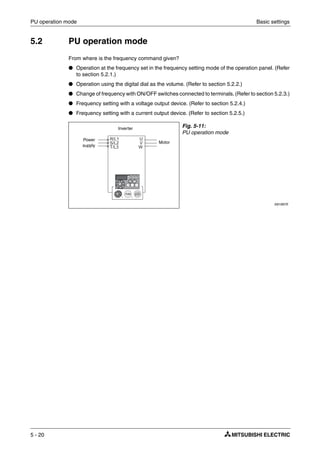
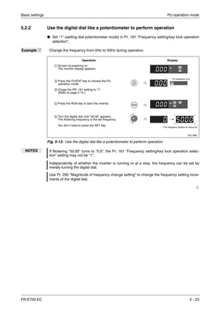
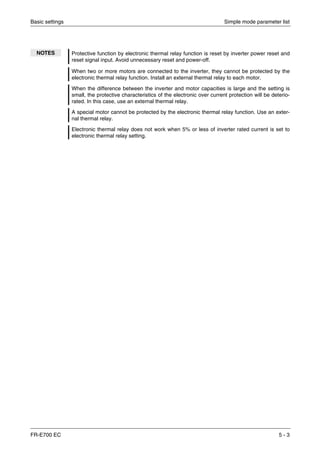
![PU operation mode Basic settings
5 - 24
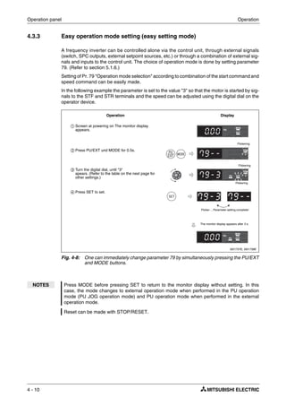
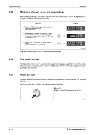
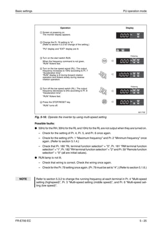
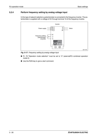
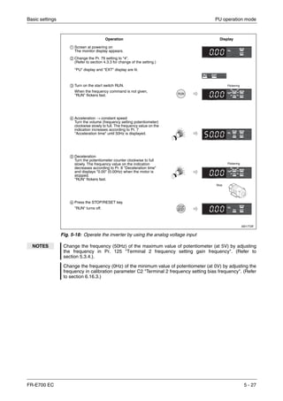
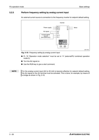
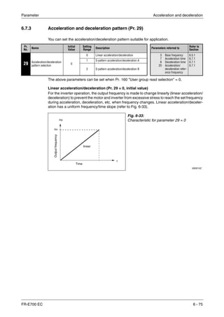
5.2.3 Use switches to give the frequency command (multi-speed setting)
In frequency inverters of the FR-E700 series up to 15 frequency setpoints (and thus rpms and
speeds) can be selected via the RH, RM, RL and REX terminals. Manually activated switches
or relay outputs of a programmble logic controller (PLC), for example, can be used to select a
frequency.
● Pr. 79 "Operation mode selection" must be set to "4" (external/PU combined operation
mode 2).
● Use the RUN key to give a start command.
● The initial values of the terminals RH, RM, RL are 50Hz, 30Hz, and 10Hz. (Refer to
section 5.3.2 to change frequencies using Pr. 4, Pr. 5 and Pr. 6.)
● Three setpoints can be selected by separately switching on the signals to the RH, RM and
RL terminals. The selection of the fourth to the seventh fixed frequency is possible through
the combination of signals of these inputs (see diagram below). The setpoints are determi-
ned by parameters 24 to 27. The REX terminal is used to select the 8th to the 15th rpm/
speed (section 6.6.1).
I001769E
Fig. 5-14: Use switches to give the frequency command
I000004aC
Fig. 5-15: Multi-speed selection by external terminals
Power supply Motor
Inverter
High speed
Middle speed
Low speed
t
RH
RM
RL
Outputfrequency[Hz]
Speed 1 (high speed)
Speed 2
(middle speed)
Speed 3
(low speed)
Speed 4
Speed 5
Speed 6
Speed 7
ON
ON
ON
ON
ON
ON ON ON
ON ON
ON](https://image.slidesharecdn.com/fr-e700-140613033232-phpapp01/85/Fr-e700-122-320.jpg)
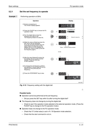
![External operation Basic settings
5 - 32
5.3.2 Use switches to give a start command and a frequency command (multi-
speed setting) (Pr. 4 to Pr. 6)
● Start command by terminal STF (STR)-PC.
● Frequency command by terminal RH, RM, RL and STR-PC.
● "EXT" must be lit. (When "PU" is lit, switch it to "EXT" with the PU/EXT key.)
● The initial values of the terminals RH, RM, RL are 50Hz, 30Hz, and 10Hz. (Use Pr. 4, Pr. 5
and Pr. 6 to change.)
● Operation at 15-speed can be performed by turning two (or three) terminals simultaneously.
(Refer to section 6.6.1.)
I0001086E
Fig. 5-23: Frequency and start command by switches
I000004aC
Fig. 5-24: Multi-speed selection by external terminals
Power supply Motor
Inverter
Forward rotation start
Reverse rotation start
High speed
Middle speed
Low speed
t
RH
RM
RL
Outputfrequency[Hz]
Speed 1 (high speed)
Speed 2
(middle speed)
Speed 3
(low speed)
Speed 4
Speed 5
Speed 6
Speed 7
ON
ON
ON
ON
ON
ON ON ON
ON ON
ON](https://image.slidesharecdn.com/fr-e700-140613033232-phpapp01/85/Fr-e700-130-320.jpg)

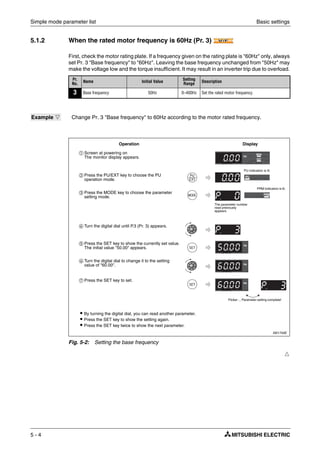
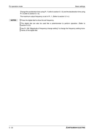
![External operation Basic settings
5 - 38
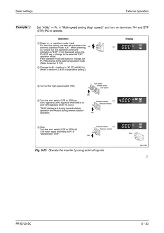
5.3.4 Change the frequency (40Hz) of the maximum value of potentiometer (at 5V)
Ħ
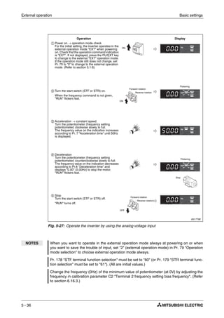
Example Ĥ The frequency of the maximum analog voltage of the potentiometer (at 5V) has to be
changed from the initial setting of 50Hz to 40 Hz. Set 40Hz in Pr. 125.
I001780E
Fig. 5-28: Change the frequency of the maximum analog value
NOTES Set the frequency at 0V using calibration parameter C2.
As other adjustment methods of frequency setting voltage gain, there are methods to adjust
with a voltage applied to across terminals 2-5 and adjust at any point without a voltage
applied. (Refer to section 6.16.3 for the setting method of calibration parameter C4.)
ቢ Turn the digital dial until P.125 (Pr. 125) appears.
ባ Press the SET key to show the currently set value.
The initial value "50.00" (50.00Hz) appears.
ቤ Turn the digital dial to change the set value to
"40.00" (40.00Hz).
ብ Press the SET key to set.
ቦ Press the MODE key twice to choose monitor/
frequency monitor.
ቧ Turn the start switch (STF or STR) on and turn the
volume (frequency setting potentiometer)
clockwise to full slowly. (Refer to Fig. 5-27,
step ባ to ቦ).
Operation Display
Flicker ... 40Hz output at 5V
input complete!
Gain
Pr. 125
Initial value
Bias
C2 (Pr. 902)
50Hz
Outputfrequency[Hz]
Frequency setting signal0
0
0
C3 (Pr. 902)
100%
5V
10V
C4 (Pr. 903)](https://image.slidesharecdn.com/fr-e700-140613033232-phpapp01/85/Fr-e700-136-320.jpg)
![Basic settings External operation
FR-E700 EC 5 - 41
5.3.6 Changethefrequency(40Hz)ofthemaximumvalueofpotentiometer(at20mA)
Ħ
Example Ĥ The frequency of the maximum analog current of the potentiometer (at 20mA) has to be
changed from the initial setting of 50Hz to 40 Hz. Set 40Hz in Pr. 126.
I001783E
Fig. 5-31: Change the frequency of the maximum analog value
NOTES Set the frequency at 4mA using calibration parameter C5.
As other adjustment methods of frequency setting current gain, there are methods to adjust
with a current flowing in the terminals 4-5 and adjust at any point without a current flowing.
(Refer to section 6.16.3 for the setting method of calibration parameter C7.)
When performing a high speed operation at 120Hz or more, setting of Pr. 18 "High speed
maximum frequency" is necessary. (Refer to section 6.4.1.)
ቢ Turn the digital dial until P.126 (Pr. 126) appears.
ባ Press the SET key to show the currently set value.
The initial value "50.00" (50.00Hz) appears.
ቤ Turn the digital dial to change the set value to
"40.00" (40.00Hz).
ብ Press the SET key to set.
ቦ Press the MODE key twice to choose monitor/
frequency monitor.
ቧ Turn the start switch STF or STR on to allow 20mA
current to flow.
(Refer to Fig. 5-30, step ባ to ቦ).
Operation Display
Flicker ... 40Hz output at 20mA
input complete!.
Gain Pr. 126
Initial value
Bias C5 (Pr. 904)
50Hz
Outputfrequency[Hz]
Frequency
setting signal
0
0
C6 (Pr. 904)
100%
20mA
C7 (Pr. 905)
20
4](https://image.slidesharecdn.com/fr-e700-140613033232-phpapp01/85/Fr-e700-139-320.jpg)

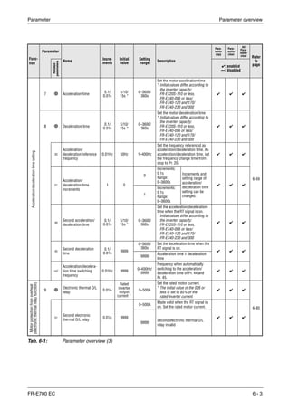
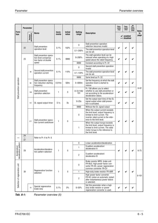
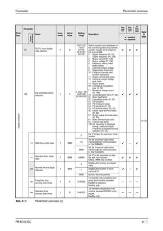
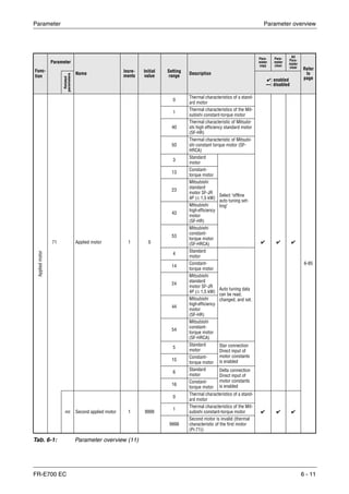
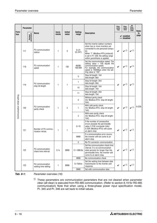
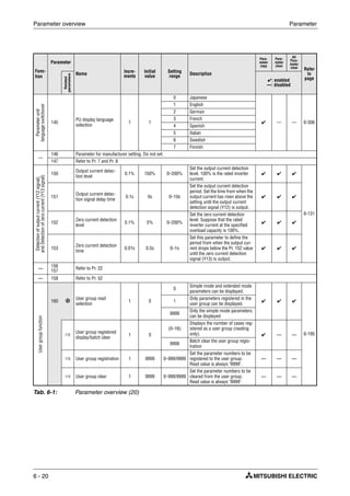
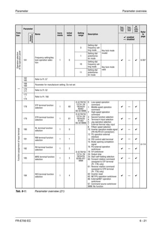
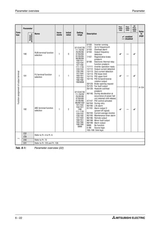
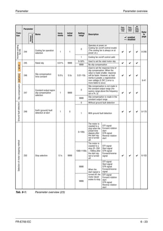
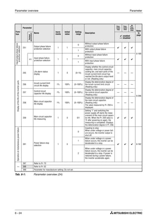
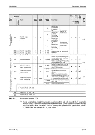
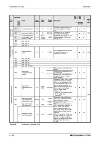
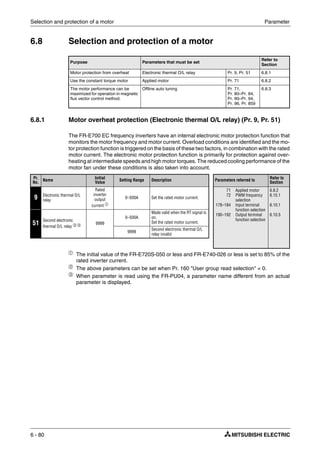
![Parameter overview Parameter
6 - 12
Func-
tion
Parameter
Name
Incre-
ments
Initial
value
Setting
range
Description
Para-
meter
copy
Para-
meter
clear
All
Para-
meter
clear Refer
to
page
Related
parameters
✔: enabled
—: disabled
Carrierfrequencyand
Soft-PWMselection
72
PWM frequency
selection
1 1 0–15
PWM carrier frequency can be
changed. The setting displayed is
in [kHz]. Note that 0 indicates
0.7kHz, 15 indicates 14.5kHz.
✔ ✔ ✔
6-172
240
Soft-PWM operation
selection
1 1
0 Soft-PWM invalid
✔ ✔ ✔
1
When Pr. 72 = "0 to 5", Soft-PWM
is valid.
Analoginputselection
73 Analog input selection 1 1
Terminal 2
input
Polarity reversible
✔ — ✔
6-174
0 0–10V
Not used
1 0–5V
10 0–10V
With
11 0–5V
267
Terminal 4 input
selection
1 0
0 Terminal 4 input 4 to 20mA
✔ — ✔1 Terminal 4 input 0 to 5V
2 Terminal 4 input 0 to 10V
Noiseeliminationat
theanaloginput
74
Input filter time
constant
1 1 0–8
The primary delay filter time con-
stant for the analog input can be
set.
A larger setting results in a larger
filter.
✔ ✔ ✔ 6-179
Resetselection/
disconnectedPU/PUstop
75
Reset selection/
disconnected PU/PU
stop
1 14 0–3/14–17
You can select the reset input
acceptance, disconnected PU
(operation panel/FR-PU04/
FR-PU07) connector detection
function and PU stop function. For
the initial value, reset always ena-
bled, without disconnected PU
detection, and with PU stop func-
tion are set.
✔ — — 6-187
Preventionof
parameterrewrite
77
Parameter write
selection
1 0
0 Write is enabled only during a stop
✔ ✔ ✔ 6-192
1 Parameter write is disabled.
2
Parameter write is enabled in any
operation mode regardless of
operation status.
Note:
Parameters that can generally be
written during operation should
not be written as well with this set-
ting.
Preventionofreverse
rotationofthemotor
78
Reverse rotation
prevention selection
1 0
0
Both forward and reverse rota-
tions allowed
✔ ✔ ✔ 6-194
1 Reverse rotation disallowed
2 Forward rotation disallowed
Tab. 6-1: Parameter overview (12)](https://image.slidesharecdn.com/fr-e700-140613033232-phpapp01/85/Fr-e700-152-320.jpg)
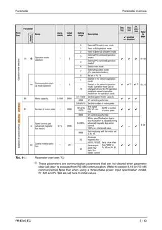
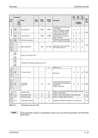
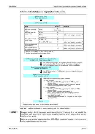
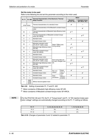
![Adjust the output torque (current) of the motor Parameter
6 - 34
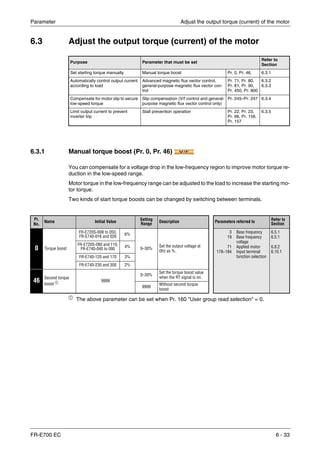
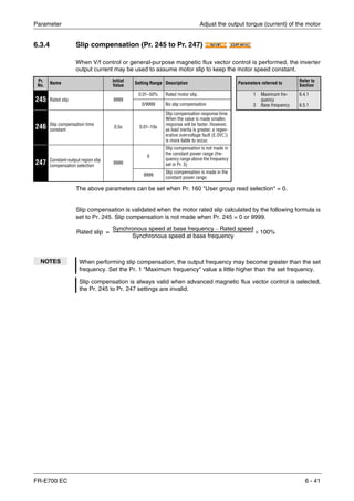
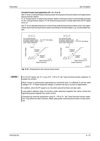
Starting torque adjustment
On the assumption that Pr. 19 "Base frequency voltage" is 100%, set the output voltage at 0Hz
in % to Pr. 0 (Pr. 46).
Set multiple base frequencies (RT signal, Pr. 46)
Use the second torque boost when changing the torque boost according to application or when
using multiple motors by switching between them by one inverter.
Pr. 46 "Second torque boost" is made valid when the RT signal turns on. The RT signal acts as
the second function selection signal and makes the other second functions valid.
Fig. 6-1:
Relationship between output frequency and
output voltage
I000001C
E
CAUTION:
Adjust the parameter little by little (about 0.5%), and check the motor status each time.
If the setting is too large, the motor will overheat. The guideline is about 10% at the
greatest.
The requirements of the motor manufacturer must also be observed.
100
50
30
[%]
fB
Setting range Pr. 0, Pr. 46
Outputvoltage](https://image.slidesharecdn.com/fr-e700-140613033232-phpapp01/85/Fr-e700-174-320.jpg)
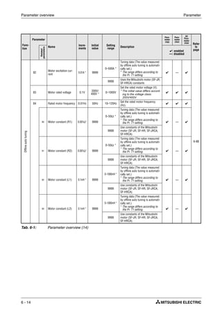
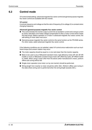
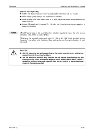
![Adjust the output torque (current) of the motor Parameter
6 - 46
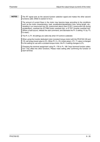
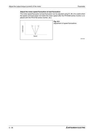
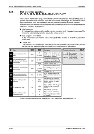
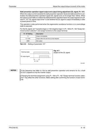
Setting of stall prevention operation in high frequency range (Pr. 22, Pr. 23, Pr. 66)
During high-speed operation above the rated motor frequency, acceleration may not be made
because the motor current does not increase. If operation is performed in a high frequency
range, the current at motor lockup becomes smaller than the rated output current of the inverter,
and the protective function (OL) is not executed if the motor is at a stop.
To improve the operating characteristics of the motor in this case, the stall prevention level can
be reduced in the high frequency region. This function is effective for performing operation up
to the high-speed range on a centrifugal separator etc.
Pr. 23 sets the change in the current limiting in the frequency range starting at the frequency set
by Pr. 66. For example, if Pr. 66 is set to 75Hz the motor stall prevention operation level at an
output frequency of 150Hz will be reduced to 75% when Pr. 23 is set to 100%, and to 66% when
Pr. 23 is set to 50% (see the formula below). Generally Pr. 66 is set to 50Hz and Pr. 23 to 100%.
Formula for stall prevention operation level:
When Pr. 23 "Stall prevention operation level compensation factor at double speed" = 9999 (in-
itial value), the stall prevention operation level is kept constant at the Pr. 22 setting up to 400Hz.
I001900E
Fig. 6-8: Stall prevention operation level
Fig. 6-9:
Stall prevention operation level when
Pr. 22 = 150 %, Pr. 23 = 100 % and
Pr. 66 = 50 Hz
I001545C
Pr. 23 = 9999
Output frequency [Hz]
Current[%]
Current limiting if the current limit was set at higher
frequency (Pr. 23).
Output frequency [Hz]
Current[%]
Setting example Pr. 22 = 150%
Pr. 23 = 100%
Pr. 66 = 50Hz
Stall prevention operation level [%] A B
Pr. 22 A–
Pr. 22 B–
--------------------------
Pr. 23 100–
100
--------------------------------××+=
where A
Pr. 66 [Hz] Pr. 22 [%]×
Output frequency [Hz]
------------------------------------------------------------- B
Pr. 66 [Hz] Pr. 22 [%]×
400Hz
-------------------------------------------------------------=,=](https://image.slidesharecdn.com/fr-e700-140613033232-phpapp01/85/Fr-e700-186-320.jpg)
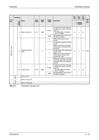
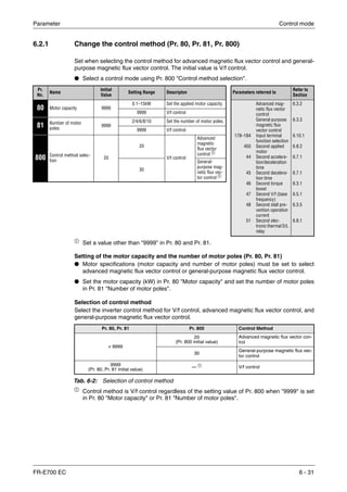
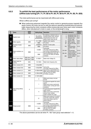
![Limit the output frequency Parameter
6 - 50
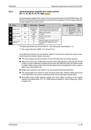
6.4 Limit the output frequency
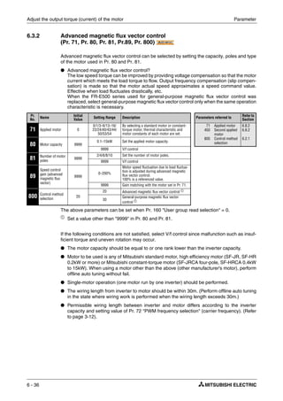
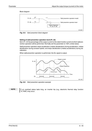
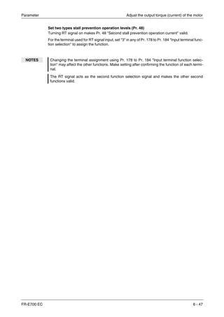
6.4.1 Maximum and minimum frequency (Pr. 1, Pr. 2, Pr. 18)
You can limit the motor speed. Clamp the upper and lower limits of the output frequency.
ቢ
The above parameter can be set when Pr. 160 "User group read selection" = 0.
Set the maximum frequency
Set the upper limit of the output frequency in Pr. 1 "Maximum frequency". If the frequency of the
frequency command entered is higher than the setting, the output frequency is clamped at the
maximum frequency.
When you want to perform operation above 120Hz, set the upper limit of the output frequency
to Pr. 18 "High speed maximum frequency". (When Pr. 18 is set, Pr. 1 automatically switches to
the frequency of Pr. 18. When Pr. 18 is set, Pr. 18 automatically switches to the frequency of
Pr. 1.)
Purpose Parameters that must be set
Refer to
Section
Set upper limit and lower limit of output
frequency
Maximum/minimum frequency Pr. 1, Pr. 2,
Pr. 18
6.4.1
Perform operation by avoiding machine
resonance points
Frequency jump Pr. 31–Pr. 36 6.4.2
Pr.
No.
Name Initial Value
Setting
Range
Description Parameters referred to
Refer to
Section
1 Maximum frequency 120Hz 0–120Hz
Set the upper limit of the output
frequency.
13
15
125
126
Starting frequency
Jog frequency
Terminal 2
frequency setting
gain frequency
Terminal 4
frequency setting
gain frequency
6.7.2
6.6.2
6.16.3
6.16.3
2 Minimum frequency 0Hz 0–120Hz
Set the lower limit of the output
frequency.
18
High speed maximum
frequency ቢ 120Hz 120–400Hz
Set when performing the opera-
tion at 120Hz or more
Fig. 6-10:
Maximum and minimum output frequency
I001100E
NOTE When performing operation above 50Hz using the frequency setting analog signal, change
Pr. 125 (Pr. 126) "Frequency setting gain". (Refer to section 6.16.3.) If only Pr. 1 or Pr. 18 is
changed, operation above 50Hz cannot be performed.
Pr. 1
Pr. 18
Clamped at the
maximum frequency
5, 10V
(20mA)
Output
frequency [Hz]
Pr. 2
Frequency
setting
0
(4mA)Clamped at the
minimum frequency](https://image.slidesharecdn.com/fr-e700-140613033232-phpapp01/85/Fr-e700-190-320.jpg)
![Set V/f pattern Parameter
6 - 54
6.5 Set V/f pattern
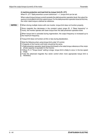
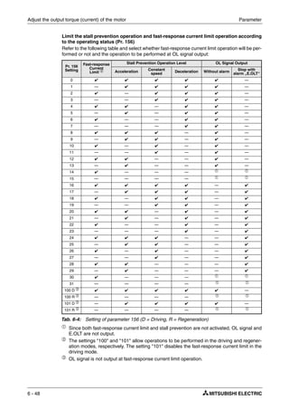
6.5.1 Base frequency, voltage (Pr. 3, Pr. 19, Pr. 47)
Used to adjust the inverter outputs (voltage, frequency) to the motor rating.
ቢ
The above parameter can be set when Pr. 160 "User group read selection" = 0.
Setting of base frequency (Pr. 3)
When operating a standard motor, generally set the rated frequency of the motor to Pr. 3 "Base
frequency".
When running the motor using commercial power supply-inverter switch-over operation, set
Pr. 3 to the same value as the power supply frequency.
If the frequency given on the motor rating plate is "60Hz" only, always set to "60Hz". It may result
in an inverter trip due to overload. Caution must be taken especially when Pr. 14 "Load pattern
selection" = "1" (variable torque load)
Purpose Parameters that must be set
Refer to
Section
Set motor ratings Base frequency, Base frequency voltage Pr. 3, Pr. 19,
Pr. 47
6.5.1
Select a V/f pattern according to
applications
Load pattern selection Pr. 14 6.5.2
Pr.
No.
Name Initial Value Setting Range Description Parameters referred to Refer to
Section
3 Base frequency 50Hz 0–400Hz
Set the frequency when the motor
rated torque is generated. (50Hz/
60Hz)
14
29
83
84
178–184
Load pattern
selection
Acceleration/decel-
eration pattern
selection
Motor rated
voltage
Rated motor fre-
quency
Input terminal
function selection
General-purpose
magnetic flux vec-
tor control
Advanced mag-
netic flux vector
control
6.5.2
6.7.3
6.8.3
6.8.3
6.10.1
6.3.3
6.3.2
19
Base frequency
voltage ቢ 8888
0–1000V Set the rated motor voltage.
8888 95% of power supply voltage
9999 Same as power supply voltage
47
Second V/f
(base frequency) ቢ 9999
0–400Hz
Set the base frequency when the RT
signal is on.
9999 Second V/f invalid
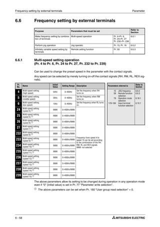
I000003aC
Fig. 6-13: Output voltage related to the output frequency
V/FV/FV/F
50 60 120
[Hz]
100
[%]
Base frequency setting range
SettingrangePr.19
Outputvoltagerelatedtothe
powersupplyvoltage
Pr. 3 = 50Hz, Pr. 19 = 9999
Pr. 3 = 60Hz, Pr. 19 = 220V](https://image.slidesharecdn.com/fr-e700-140613033232-phpapp01/85/Fr-e700-194-320.jpg)
![Set V/f pattern Parameter
6 - 56
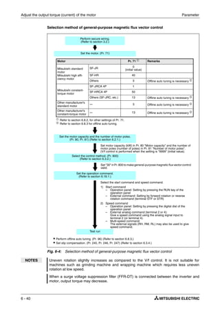
6.5.2 Load pattern selection (Pr. 14)
You can select the optimum output characteristic (V/f characteristic) for the application and load
characteristics.
The above parameter can be set when Pr. 160 "User group read selection" = 0.
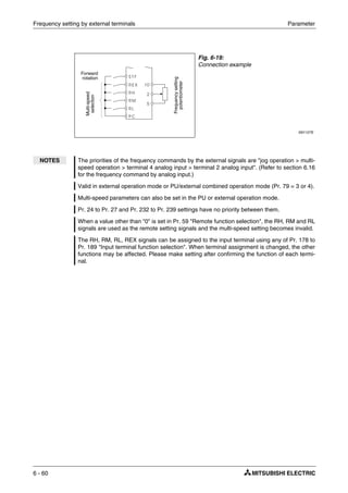
For constant-torque load (Pr. 14 = 0, initial value)
At or less than the base frequency voltage, the output voltage varies linearly with the output fre-
quency. Set this value when driving the load whose load torque is constant if the speed varies,
e.g. conveyor, cart or roll drive.
For variable-torque load (Pr. 14 = 1)
At or less than the base frequency voltage, the output voltage varies with the output frequency
in a square curve. Set this value when driving the load whose load torque varies in proportion
to the square of the speed, e.g. fan or pump.
Pr.
No.
Name Initial
Value
Setting Range Description Parameters referred to Refer to
Section
14 Load pattern selection 0
0 For constant torque load 0
46
3
178–184
Torque boost
Second torque
boost
Base frequency
Input terminal func-
tion selection
General-purpose
magnetic flux vec-
tor control
Advanced magnetic
flux vector control
6.3.1
6.3.1
6.5.1
6.10.1
6.3.3
6.3.2
1 For variable torque load
2
For constant torque elevators
(at reverse rotation boost of
0%)
3
For constant torque elevators
(at forward rotation boost of
0%)
Fig. 6-14:
Constant-torque load
I001322C
Fig. 6-15:
Variable-torque load
I001323C
[%]
100
Hz
Pr. 3 Base frequency
Output frequency
Outputvoltage
[%]
100
Hz
Pr. 3 Base frequency
Output frequency
Outputvoltage](https://image.slidesharecdn.com/fr-e700-140613033232-phpapp01/85/Fr-e700-196-320.jpg)
![Parameter Frequency setting by external terminals
FR-E700 EC 6 - 59
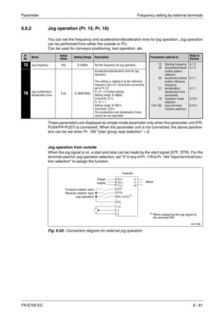
Operation is performed at the frequency set in Pr. 4 when the RH signal turns on, Pr. 5 when the
RM signal turns on, and Pr. 6 when the RL signal turns on.
Frequency from speed 4 to speed 15 can be set according to the combination of the RH, RM,
RL and REX signals. Set the running frequencies in Pr. 24 to Pr. 27, Pr. 232 to Pr. 239. (In the
initial value setting, speed 4 to speed 15 are unavailable.)
ቢ
When "9999" is set in Pr. 232 "Multi-speed setting (speed 8)", operation is performed at
frequency set in Pr. 6 when RH, RM and RL are turned off and REX is turned on.
Fig. 6-17:
Multi-speed selection by external terminals
I002062E
I002063E
Fig. 6-18: Multi-speed selection by external terminals
NOTES In the initial setting, if two or three speeds are simultaneously selected, priority is given to
the set frequency of the lower signal. For example, when the RH and RM signals turn on, the
RM signal (Pr. 5) has a higher priority.
The RH, RM, RL signals are assigned to the terminal RH, RM, RL in the initial setting. By
setting "0 (RL)", "1 (RM)", "2 (RH)" in any of Pr. 178 to Pr. 184 "Input terminal function assig-
nment", you can assign the signals to other terminals.
For the terminal used for REX signal input, set "8" in any of Pr. 178 to Pr. 184 to assign the
function.
Outputfrequency[Hz]
time
ON
ON
ON
Speed 1 (high speed)
Speed 2 (middle speed)
Speed 3 (low speed)
Outputfrequency[Hz]
Speed 8
Speed 11
Speed 9
Speed 10
Speed 12
Speed 13
Speed 14
Speed 15
ON
ON
ON ON
ON ON ON ON
ON
ON
ቢ
ON ON ON
ON
time
ON ON ON
ONONON
ON ON ON ON
ONONONON
Speed 7
Speed 6
Speed 5
Speed 4](https://image.slidesharecdn.com/fr-e700-140613033232-phpapp01/85/Fr-e700-199-320.jpg)
![Parameter Frequency setting by external terminals
FR-E700 EC 6 - 65
6.6.3 Remote setting function (Pr. 28)
Even if the operation panel is located away from the enclosure, you can use contact signals to
perform continuous variable-speed operation, without using analog signals.
The above parameter can be set when Pr. 160 "User group read selection" = 0.
Pr. 59 can be used to select a digital motor potentiometer. Setting Pr. 59 to a value of "1" ac-
tivates the frequency setting storage function, so that the stored value is also stored when the
power is switched off. The last frequency value is stored in the E²PROM. The delete instruction
only applies to the data stored in RAM.
When Pr. 59 is set to any of "1 to 3" (remote setting function valid), the functions of the RH, RM
and RL signals are changed: RH ⇒ acceleration, RM ⇒ deceleration and RL ⇒ clear.
* External operation frequency (other than multi-speed) or PU running frequency.
Pr.
No.
Name Initial
Value
Setting
Range
Description
Parameters referred to Refer to
SectionRH, RM and RL
signal function
Frequency setting
storage function
59 Remote function
selection
0
0 Multi-speed setting — 1
18
7
8
44
45
178–184
Maximum
frequency
High speed
maximum
frequency
Acceleration time
Deceleration time
Second accelera-
tion/deceleration
time
Second decelera-
tion time
Input terminal
function selection
6.4.1
6.4.1
6.7.1
6.7.1
6.7.1
6.7.1
6.10.1
1 Remote setting ✔
2 Remote setting —
3 Remote setting
—
(Turning STF/STR off
clears remote setting
frequency.)
Fig. 6-25:
Connection diagram for remote setting
I001132E
I001133E
Fig. 6-26: Example of the remote setting function
Forward rotation
Acceleration
Deceleration
Clear
Inverter
Acceleration RH
Deceleration RM
Clear RL
Forward rotation STF
Power supply
Pr. 59 = 1
Pr. 59 = 2, 3
Pr. 59 = 1, 2
Pr. 59 = 3
Output
frequency[Hz]
Time
ON
ON
ON
ON EIN ON ON
ON
ON
ONON](https://image.slidesharecdn.com/fr-e700-140613033232-phpapp01/85/Fr-e700-205-320.jpg)
![Frequency setting by external terminals Parameter
6 - 68
During jog operation or PID control operation, the remote setting function is invalid.
Set frequency = 0 Hz
● Even when the remotely-set frequency is cleared by turning on the RL (clear) signal after
turn off (on) of both the RH and RM signals, the inverter operates at the remotely-set
frequency stored in the last operation if power is reapplied before one minute has elapsed
since turn off (on) of both the RH and RM signals.
● When the remotely-set frequency is cleared by turning on the RL (clear) signal after turn off
(on) of both the RH and RM signals, the inverter operates at the frequency in the remotely-
set frequency cleared state if power is reapplied after one minute has elapsed since turn off
(on) of both the RH and RM signals.
I001134C
Fig. 6-27: Outputting the remotely-set frequency stored last time
I001135C
Fig. 6-28: Outputting the current set frequency
E
CAUTION:
When Pr. 59 is set to "1" the motor will restart automatically after a power failure if
there is an active rotation direction signal.
Acceleration RH
Deceleration RM
Clear RL
Forward rotation STF
Power supply
Remotely-set frequency stored last time
< 1 minute
Output
frequency[Hz]
Remotely-set frequency stored last time
ON
ON
ON
ON
ON
ON
OFF
Time
Acceleration RH
Deceleration RM
Clear RL
Forward rotation STF
Power supply
Operation is performed at the set
frequency 0Hz.
> 1 minute
Output
frequency[Hz]
Remotely-set frequency stored last time
ON
ON
ON ON
ON
ON
Time
OFF](https://image.slidesharecdn.com/fr-e700-140613033232-phpapp01/85/Fr-e700-208-320.jpg)
![Parameter Acceleration and deceleration
FR-E700 EC 6 - 71
Change the setting range and increments of the acceleration/deceleration time (Pr. 21)
Use Pr. 21 to set the acceleration/deceleration time and minimum setting range.
Setting "0" (initial value)............. 0 to 3600s (minimum setting increments 0.1s)
Setting "1".................................. 0 to 360s (minimum setting increments 0.01s)
Set two kinds of acceleration/deceleration times (RT signal, Pr. 44, Pr. 45, Pr. 147)
Pr. 44 and Pr. 45 are valid when the RT signal is on, or the output frequency reaches or exceeds
the setting of Pr. 147. Switching the parameter sets allows you to operate motors with different
specifications and capabilities with the frequency inverter.
When "9999" is set to Pr. 45, the deceleration time becomes equal to the acceleration time
(Pr. 44).
For the RT signal, set "3" in any of Pr. 178 to Pr. 184 "Input terminal function selection" to assign
the function.
When RT signal is off, automatic switching of the acceleration/deceleration time is available with
Pr. 147.
ቢ When the RT signal turns on, the acceleration/deceleration time switches to the second
acceleration/deceleration time even when the output frequency is not reached to Pr. 147
setting.
E
CAUTION:
Changing the Pr. 21 setting changes the acceleration/deceleration setting (Pr. 7, Pr. 8,
Pr. 16, Pr. 44, Pr. 45).
(The Pr. 611 "Acceleration time at a restart" setting is not affected.)
Example:
When Pr. 21 = 0, setting "5.0" s in Pr. 7 and "1" in Pr. 21 automatically changes the
Pr. 7 setting to "0.5" s.
Pr. 147 Acceleration/Deceleration Time Description
9999 (Initial value) Pr. 7, Pr. 8
No automatic switching of the accel-
eration/deceleration time
0.00Hz Pr. 44, Pr. 45
Second acceleration/deceleration
time from a start
0.00 Hz ≤ Pr. 147 ≤ Set frequency
Output frequency < Pr. 147:
Pr. 7, Pr. 8
Pr. 147 ≤ Output frequency:
Pr. 44, Pr. 45
Acceleration/deceleration time auto-
matic switching ቢ
Set frequency < Pr. 147 Pr. 7, Pr. 8
No automatic switching, since output
frequency will not reach the switch-
ing frequency
Tab. 6-5: Acceleration/deceleration times in dependence on Parameter 147
I001929E
Fig. 6-30: Automatic switching of the acceleration/deceleration time
Set frequency
Acceleration time
t
Output frequency [Hz]
Deceleration time](https://image.slidesharecdn.com/fr-e700-140613033232-phpapp01/85/Fr-e700-211-320.jpg)
![Acceleration and deceleration Parameter
6 - 72
S-shaped acceleration/deceleration pattern
If a S-shaped acceleration/deceleration pattern A is selected in pr. 29, the set time is the period
required to reach the base frequency set in Pr. 3 "Base frequency".
Acceleration/deceleration time formula when the set frequency is the base frequency or higher.
T: Acceleration/deceleration time setting value (s)
f: Set frequency (Hz)
Guideline for acceleration/deceleration time when Pr. 3 Base frequency = 50Hz (0Hz to set fre-
quency).
NOTE You will find a detailed description of this parameter in section 6.7.3.
Acceleration/deceleration
time [s]
Frequency Setting [Hz]
50 120 200 400
5 5 16 38 145
15 15 47 115 435
Tab. 6-6: Acceleration/deceleration time at a base frequency of 50Hz
NOTES Changing terminal assignment may affect the other functions. Make setting after confirming
the function of each terminal. (Refer to section 6.10.3.)
If the Pr. 20 setting is changed, the Pr. 125 and Pr. 126 (frequency setting signal gain fre-
quency) settings do not change. Set Pr. 125 and Pr. 126 to adjust the gains.
When the Pr. 7, Pr. 8, Pr. 44 and Pr. 45 settings are 0.03s or less, the acceleration/deceler-
ation time is 0.04s. At that time, set Pr. 20 to "120Hz" or less.
If the acceleration/deceleration time is set, the actual motor acceleration/deceleration time
cannot be made shorter than the shortest acceleration/deceleration time determined by the
mechanical system J (inertia moment) and motor torque.
t
4
9
---
T
Pr. 3( )
2
-------------------- f
2
×
5
9
---+× T=](https://image.slidesharecdn.com/fr-e700-140613033232-phpapp01/85/Fr-e700-212-320.jpg)
![Parameter Acceleration and deceleration
FR-E700 EC 6 - 73
6.7.2 Starting frequency and start-time hold function
You can set the starting frequency and hold the set starting frequency for a certain period of time.
Set these functions when you need the starting torque or want to smooth motor drive at a start.
The above parameters can be set when Pr. 160 "User group read selection" = 0.
Starting frequency setting (Pr. 13)
The motor is started with the specified start frequency as soon as the frequency inverter re-
ceives a start signal and a frequency setting that is greater than or equal to the preset starting
frequency.
Pr.
No.
Name Initial Value Setting Range Description Parameters referred to
Refer to
Section
13 Starting frequency 0.5Hz 0–60Hz
Frequency at start can be set in
the range 0 to 60Hz.
You can set the starting fre-
quency at which the start signal
is turned on.
2 Minimum
frequency
6.4.1
571 Holding time at start 9999
0.0–10.0s
Set the holding time of Pr. 13
"Starting frequency".
9999
Holding function at a start is
invalid
Fig. 6-31:
Starting frequency parameter
I000008C
NOTE The inverter will not start if the frequency setting signal is less than the value set in Pr. 13.
Example Ĥ When 5Hz is set in Pr. 13, the motor will not start running until the frequency setting signal
reaches 5Hz.
Ħ
P
WARNING:
Note that when Pr. 13 is set to any value lower than Pr. 2 "Minimum frequency", simply
turning on the start signal will run the motor at the preset frequency even if the
command frequency is not input.
60
Pr.13
0
Output
frequency [Hz]
Settingrange
ONForward rotation
t
Hz](https://image.slidesharecdn.com/fr-e700-140613033232-phpapp01/85/Fr-e700-213-320.jpg)
![Acceleration and deceleration Parameter
6 - 74
Start-time hold function (Pr. 571)
This function holds the time set in Pr. 571 and the output frequency set in Pr. 13 "Starting
frequency".
This function performs initial excitation to smooth the motor drive at a start.
I000399C
Fig. 6-32: Holding time at start
NOTES When the start signal was turned off during start-time hold, deceleration is started at that
point.
At switching between forward rotation and reverse rotation, the starting frequency is valid
but the start-time hold function is invalid.
When Pr. 13 = 0Hz, the starting frequency is held at 0.01Hz.
Pr. 571
Pr. 13
Output
frequency [Hz]
ON
t
Forward rotation OFF](https://image.slidesharecdn.com/fr-e700-140613033232-phpapp01/85/Fr-e700-214-320.jpg)
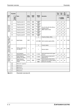
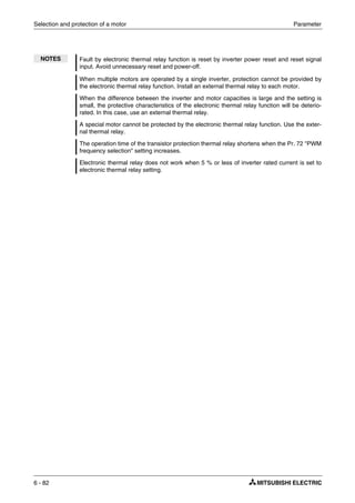
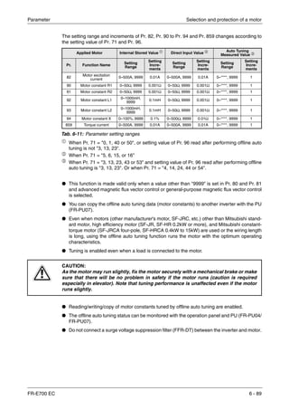
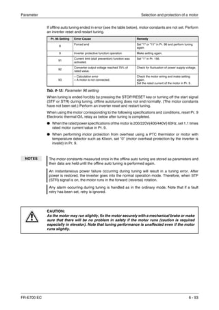
![Parameter Selection and protection of a motor
FR-E700 EC 6 - 81
Electronic thermal O/L relay (Pr. 9)
Set the rated current [A] of the motor in Pr. 9. (When the power supply specification is 400V/
440V 60Hz, set the 1.1 times the rated motor current.)
Set "0" to Pr. 9 when you do not want to activate the electronic thermal relay function, e.g. when
using an external thermal relay with the motor. (Note that the output transistor protection of the
inverter functions (E.THT).)
When using the Mitsubishi constant-torque motor set "1, 13 to 16, 50, 53 or 54" to Pr. 71. (This
provides a 100% continuous torque characteristic in the low-speed range.) After this set the rat-
ed current of the motor to Pr. 9.
The figure below shows the electronic thermal relay function operation characteristic. The re-
gion on the right of the characteristic curve is the operation region. The region on the left of the
characteristic curve is the non-operation region.
ቢ When a value 50% of the inverter rated output current (current value) is set to Pr. 9.
ባ
The % value denotes the percentage to the inverter rated output current. It is not the
percentage to the motor rated current.
ቤ When you set the electronic thermal relay function dedicated to the Mitsubishi constant-
torque motor, this characteristic curve applies to operation at 6Hz or higher.
I001792E
Fig. 6-36: Electronic thermal relay function operation characteristic
Inverter output power (%)
(% to the rated input current)
(s)unitdisplayin
thisregion
(min)unitdisplay
inthisregion
Pr. 9 = 50 % setting of
the inverter rating % ቢ ባ Pr. 9 = 100 % setting of
the inverter rating ቢ ባ
Range for
transistor
protection
or more ቤ
Characteristic when electronic thermal
relay function for motor protection is
turned off (When Pr. 9 setting is 0(A)).
or more ቤ
Operation range
– Range on the right of characteristic curve
Non operation range
– Range on the left of characteristic curve
Operationtime(min)Operationtime(s)](https://image.slidesharecdn.com/fr-e700-140613033232-phpapp01/85/Fr-e700-221-320.jpg)
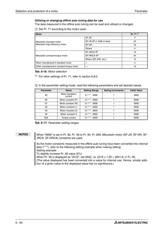
![Parameter Selection and protection of a motor
FR-E700 EC 6 - 95
Method to set the motor constants without using the offline auto tuning data
The Pr. 90 to Pr. 94 motor constants may either be entered in [ Ω, mΩ ] or in [mH]. Before starting
operation, confirm which motor constant unit is used.
To enter the Pr. 90 to Pr. 94 motor constants in [Ω]/[mΩ]
ቢ Set Pr. 71 according to the motor used:
ባ In the parameter setting mode, read the following parameters and set desired values.
Iq = torque current, I100 = rated current, I0 = no load current
ቤ Refer to the following table and set Pr. 83 and Pr. 84.
Star Connection Motor Delta Connection Motor
Standard motor 5 6
Constant-torque motor 15 16
Tab. 6-18: Setting of parameter 71
Pr. Name Setting Range Setting Inrements Initial Value
82
Motor excitation current
(no load current) 0–500A, 9999 0.01A 9999
90 Motor constant R1 0–50Ω, 9999 0.001Ω 9999
91 Motor constant R2 0–50Ω, 9999 0.001Ω 9999
92 Motor constant L1 0–50Ω, 9999 0.001Ω 9999
93 Motor constant L2 0–50Ω, 9999 0.001Ω 9999
94 Motor constant X 0–500Ω, 9999 0.01Ω 9999
859 Torque current 0–500A, 9999 0.01A 9999
Tab. 6-19: Setting of parameter 82, 90 to 94 and 859
Pr. Name Setting Range Setting Inrements Initial Value
83 Motor rated voltage 0–1000V 0.1V 400V
84 Rated motor frequency 10–120Hz 0.01Hz 50Hz
Tab. 6-20: Setting of parameter 83 and 84
NOTES When "9999" is set in Pr. 82, Pr. 90 to Pr. 94, Pr. 859, Mitsubishi motor (SF-JR, SF-HR, SF-
JRCA, SF-HRCA) constants are used.
If "star connection" is mistaken for "delta connection" or vice versa during setting of Pr. 71,
advanced magnetic flux vector control and general-purpose magnetic flux vector control
cannot be exercised properly.
Iq I100
2
I0
2
–=](https://image.slidesharecdn.com/fr-e700-140613033232-phpapp01/85/Fr-e700-235-320.jpg)
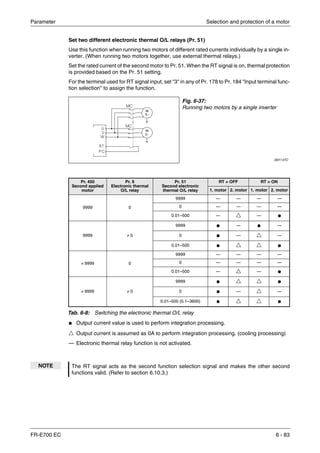
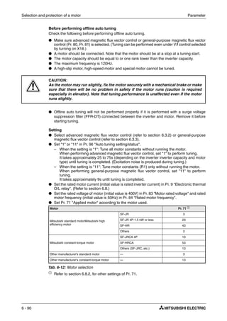
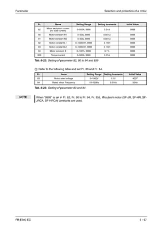
![Selection and protection of a motor Parameter
6 - 96
To enter the Pr. 90 and Pr. 94 motor constants in [mH]
ቢ Set Pr. 71 according to the motor used:
ቢ
For other settings of Pr. 71, refer to section 6.8.2.
ባ In the parameter setting mode, read the following parameters and set desired values.
Calculate the Pr. 94 value from the following formula.
R1: Primary resistance
R2: Secondary resistance
l1: Primary leakage inductance
l2: Secondary leakage inductance
M: Excitation inductance
S: Slip
L1 = l1 + M: Primary inductance
L2 = l2 + M: Secondary inductance
Motor Pr. 71 ቢ
Mitsubishi standard motor,
Mitsubishi high efficiency motor
SF-JR 0
SF-HR 40
Mitsubishi constant-torque motor
SF-JRCA 4P 1
SF-HRCA 50
Tab. 6-21: Motor selection
Fig. 6-40:
Motor equivalent circuit diagram
I001556E
Pr. 94 1
M
2
L1 L2×
---------------------–
⎝ ⎠
⎛ ⎞ 100 [%]×=
R1 l1 l2
M R2/S
U](https://image.slidesharecdn.com/fr-e700-140613033232-phpapp01/85/Fr-e700-236-320.jpg)
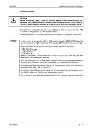
![Parameter Motor brake and stop operation
FR-E700 EC 6 - 99
Operation frequency setting (Pr. 10)
When the frequency at which the DC injection brake operates is set to Pr. 10, the DC injection
brake is operated when this frequency is reached during deceleration.
Operation time setting (Pr. 11)
Use Pr. 11 to set the duration period the DC injection brake is applied.
When the motor does not stop due to large load moment (J), increasing the setting produces an
effect.
When Pr. 11 = 0s, the DC injection brake is not operated. (At a stop, the motor coasts.)
Fig. 6-41:
When Pr. 11 is set to a value between 0.1
and 10s
I000007C
100
t
t
Outputfrequency[Hz]
DCinjectionbrake
voltage
Pr. 10
Pr. 11
Pr. 12](https://image.slidesharecdn.com/fr-e700-140613033232-phpapp01/85/Fr-e700-239-320.jpg)
![Motor brake and stop operation Parameter
6 - 102
When a high power factor converter (FR-HC) is used and automatic restart after instan-
taneous power failure function is made valid.
● When automatic restart after instantaneous power failure function of both the FR-HC and
inverter is made valid (when avalue other than "9999" is set in Pr. 57 "Restart coasting time"),
set "2" in Pr. 30.
● Set Pr. 70 to "0%" (initial value).
● When the FR-HC detects power failure during inverter operation, the RDY signal turns on,
resulting in the motor coasting. Turning the RDY signal off after power restoration, the inverter
detects the motor speed (depends on the Pr. 162 "Automatic restart after instantaneous
power failure selection") and restarts automatically after instantaneous power failure.
Regenerative brake duty alarm output and alarm signal (RBP signal)
● [RB] appears on the operation panel and an alarm signal (RBP) is output when 85% of the
regenerative brake duty set in Pr. 70 is reached. If the regenerative brake duty reaches 100%
of the Pr. 70 setting, a regenerative overvoltage (E.OV1 to E.OV3) occurs. Note that [RB] is
not displayed when Pr. 30 = "0".
● The inverter does not trip even when the alarm (RBP) signal is output.
● For the terminal used for the RBP signal output, assign the function by setting "7 (positive
logic) or 107 (negative logic)" in any of Pr. 190 to Pr. 192 "Output terminal function selection".
I001566E
Fig. 6-42: Regenerative overload
NOTES The MRS signal can also be used instead of the X10 signal.
Refer to section 3.7 for connecting the high-duty brake resistor (MRS, FR-ABR), brake unit
(FR-BU2), high power factor converter (FR-HC), and power regeneration common converter
(FR-CV).
When terminal assignment is changed using Pr. 178 to Pr. 184 "Input terminal function
selection" and Pr. 190 to Pr. 192 "Output terminal function selection", the other functions
may be affected. Make setting after confirming the function of each terminal.
E
CAUTION:
The value set in Pr. 70 must not exceed the setting of the brake resistor used.
Otherwise, the resistor can overheat.
Regenerative brake
pre-alarm (RBP)
Time
Ratio of the brake
duty to the Pr. 70
setting (%)
OFF ON ON
100 %
85 %
100 %: Overvoltage tripping](https://image.slidesharecdn.com/fr-e700-140613033232-phpapp01/85/Fr-e700-242-320.jpg)
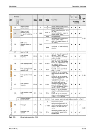
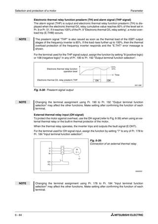
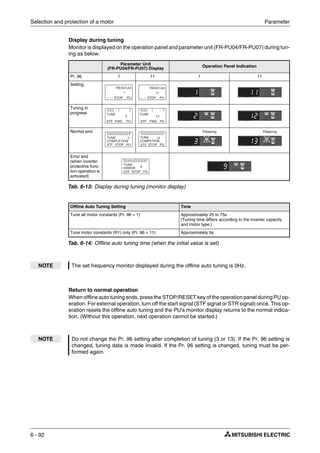
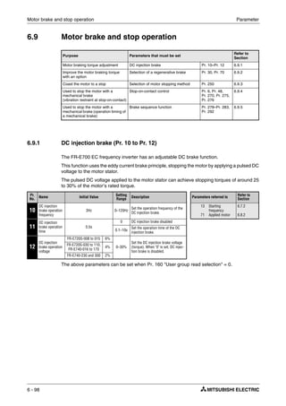
![Parameter Motor brake and stop operation
FR-E700 EC 6 - 103
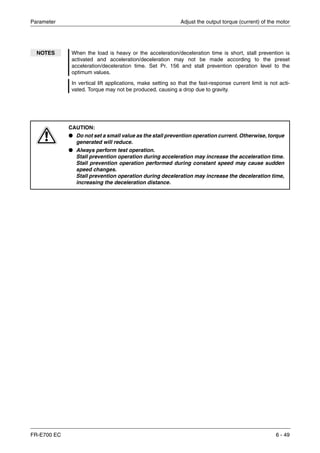
6.9.3 Stop selection (Pr. 250)
Used to select the stopping method (deceleration to a stop or coasting) when the start signal
turns off. Used to stop the motor with a mechanical brake, etc. together with switching off of the
start signal. You can also select the operations of the start signals (STF/STR). (Refer to
section 6.10.4 for start signal selection.)
The above parameter can be set when Pr. 160 "User group read selection" = 0.
Set Pr. 250 to "9999" (initial value) or "8888". The motor decelerates to a stop when the start sig-
nal (STF/STR) turns off.
Pr.
No.
Name
Initial
Value
Setting
Range
Description
Parameters referred to
Refer to
SectionStart Signal
(STF/STR)
Stop Operation
250 Stop selection 9999
0–100s
STF: Forward
rotation start
STR: Reverse rotation
start
The motor is coasted to
a stop when the preset
time elapses after the
start signal is turned off.
7
8
13
Acceleration time
Deceleration time
Starting frequency
6.7.1
6.7.1
6.7.2
1000s
–
1100s
STF: Start signal
STR: Forward/reverse
signal
The motor is coasted to
a stop (Pr. 250 − 1000)s
after the start signal is
turned off.
9999
STF: Forward
rotation start
STR: Reverse
rotation start
When the start signal is
turned off, the motor
decelerates to stop.
8888
STF: Start signal
STR: Forward/reverse
signal
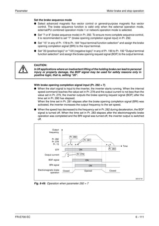
I001143E
Fig. 6-43: Stop operation when parameter 250 = 9999
Output
frequency [Hz]
Start signal
RUN signal
DC brake
Deceleration starts when start signal turns off
Deceleration time (Time set to Pr. 8, etc.)
Time
ON
ON
OFF
OFF](https://image.slidesharecdn.com/fr-e700-140613033232-phpapp01/85/Fr-e700-243-320.jpg)
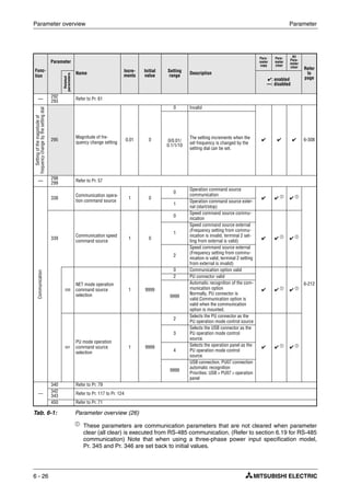
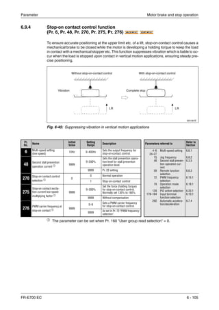
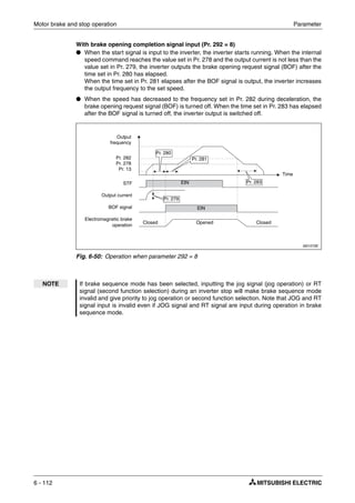
![Motor brake and stop operation Parameter
6 - 104
Use Pr. 250 to set the time from when the start signal turns off until the output is shut off. When
any of "1000" to "1100" is set, the output is shut off after (Pr. 250 − 1000)s.
The output is shut off when the time set in Pr. 250 has elapsed after the start signal had turned
off. The motor coasts to a stop.
I001144E
Fig. 6-44: Stop operation when parameter 250 ≠ 8888 or 9999
NOTES The RUN signal turns off when the output stops.
Stop selection is invalid when the following functions are activated.
ț Power failure stop function (Pr. 261)
ț PU stop (Pr. 75)
ț Deceleration stop because of communication error (Pr. 502)
ț Emergency stop by LonWorks communication
When setting of Pr. 250 is not 9999 nor 8888, acceleration/deceleration is performed
according to the frequency command, until start signal is OFF and output is shutoff.
When the start signal is turned on again during motor coasting, the motor starts at Pr. 13
"Starting frequency".
Output
frequency [Hz]
Start signal
RUN signal
Motor coasts to stop
Output is shut off when set time elapses after start
signal turned off
Pr. 250
Time
ON
ON
OFF
OFF](https://image.slidesharecdn.com/fr-e700-140613033232-phpapp01/85/Fr-e700-244-320.jpg)
![Parameter Motor brake and stop operation
FR-E700 EC 6 - 113
Protective functions
If any of the following errors occurs in the brake sequence mode, the inverter results in a fault,
trips, and turns off the brake opening request signal (BOF).
Fault
Display
Description
E.MB4
Although more than 2s have elapsed after the start command (forward or reverse rotation) is input,
the brake opening request signal (BOF) does not turn on.
E.MB5
Although more than 2s have elapsed after the brake opening request signal (BOF) turned on, the
brake opening completion signal (BRI) does not turn on.
E.MB6
Though the inverter had turned on the brake opening request signal (BOF), the brake opening com-
pletion signal (BRI) turned off midway.
E.MB7
Although more than 2s have elapsed after the brake opening request signal (BOF) turned off at a
stop, the brake opening completion signal (BRI) does not turn off.
Tab. 6-26: Protective functions
NOTES A too large setting of Pr. 278 "Brake opening frequency" activates stall prevention operation
and may cause E.MB4.
If the sum of the time between Pr. 13 "Starting frequency" and Pr. 278 "Brake opening fre-
quency" + Pr. 280 "Brake opening current detection time" is more than 2s, E.MB4 occurs.
Output frequency [Hz]
Brake opening request
(BOF signal)
Time
ON
Outputfrequency[Hz]](https://image.slidesharecdn.com/fr-e700-140613033232-phpapp01/85/Fr-e700-253-320.jpg)
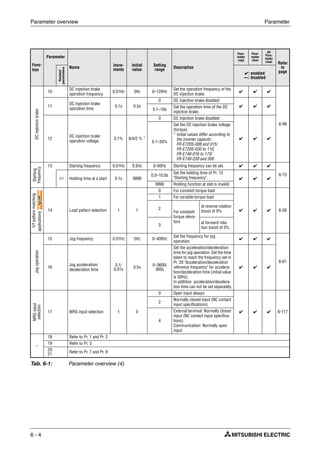
![Monitor display and monitor output signals Parameter
6 - 136
6.11 Monitor display and monitor output signals
6.11.1 Speed display and speed setting (Pr. 37)
You can output RPM rates, speeds and throughput volumes based on the output frequency to
the displays of the operation panels, FR-PU04 and FR-PU07 parameter units or to the AM out-
put.
The above parameters can be set when Pr. 160 "User group read selection" = 0.
The maximum value of the setting range differs according to the Pr. 1 "Maximum frequency" (Pa-
rameter 18 "High speed maximum frequency") and it can be calculated from the following for-
mula:
Note that the maximum setting value of Pr. 37 is 9998 if the result of the above formula exceeds
9998.
To display the machine speed set Pr. 37 to the reference value for the speed to be shown at
60Hz. For example, if the speed is 55m/min at 60Hz set Pr. 37 to "55". The display will then show
"55" when the motor frequency is 60Hz.
Purpose Parameters that must be set
Refer to
Section
Display motor speed
Set speed
Speed display and speed setting Pr. 37 6.11.1
Change PU monitor display data DU/PU main display data selection
Cumulative monitor clear
Pr. 52, Pr. 54,
Pr. 170, Pr. 171,
Pr. 268, Pr. 563,
Pr. 564
6.11.2
Change of the monitor output from
terminal AM
Terminal AM function selection Pr. 158 6.11.3
Set the reference of the monitor
output from terminal AM
Terminal AM standard setting Pr. 55, Pr. 56 6.11.3
Adjust terminal AM outputs Terminal AM calibration Pr. 645, Pr. 900 6.11.4
Pr.
No. Name
Initial
Setting
Setting
Range Description Parameters referred to
Refer to
Section
37 Speed display 0
0 Frequency display, setting 1
52
800
Maximum
frequency
DU/PU main dis-
play data selection
Control method
selection
6.4.1
6.11.2
6.3.2
0.01–9998 Set the machine speed at 60Hz.
Maximum setting value of Pr. 37
16777.215 60 [Hz]×
Setting value of Pr. 1(Pr. 18) [Hz]
----------------------------------------------------------------------------------------<](https://image.slidesharecdn.com/fr-e700-140613033232-phpapp01/85/Fr-e700-276-320.jpg)
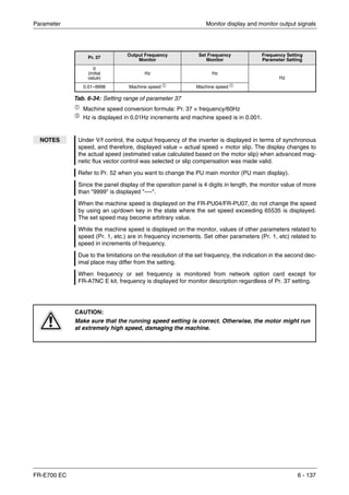
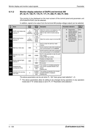
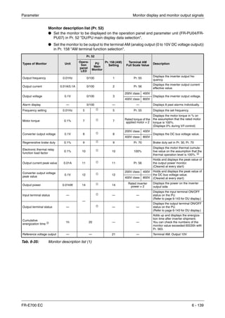
![Monitor display and monitor output signals Parameter
6 - 140
ቢ Frequency setting to output terminal status on the PU main monitor are selected by "other
monitor selection" of the parameter unit (FR-PU04/FR-PU07).
ባ
The cumulative energization time and actual operation time are accumulated from 0 to 65535
hours, then cleared, and accumulated again from 0.When the operation panel is used, the
time is displayed up to 65.53 (65530h) on the assumption that 1h = 0.001, and thereafter,
it is added up from 0.
ቤ Actual operation time is not accumulated when the cumulative operation time is less than
1h until turning off of the power supply.
ብ
When using the parameter unit (FR-PU04/FR-PU07), "kW" is displayed.
ቦ Since the panel display of the operation panel is 4 digits in length, the monitor value of more
than "9999" is displayed "----".
ቧ
Larger thermal value between the motor thermal and transistor thermal is displayed.
A value other than 0% is displayed if the ambient temperature (heatsink temperature) is high
even when the inverter is at a stop.
Types of Monitor Unit
Pr. 52
Pr. 158 (AM)
Setting
Terminal
AM
Full Scale
Value
Description
Opera-
tion
panel
LED
PU
Main
Monitor
Actual operation
time ባ ቤ 1h 23 — —
Adds up and displays the inverter
operation time.
You can check the numbers of the
monitor value exceeded 65535h with
Pr. 564. Can be cleared by Pr. 171.
(Refer to page 6-144.)
Motor load factor 0.1% 24 24 200%
Displays the output current value on
the assumption that the inverter rated
current value is 100%.
Monitor value = output power monitor
value/rated inverter current × 100 [%]
Cumulative power ቦ
0.01kWh ብ
25 — —
Adds up and displays the power
amount based on the output power
monitor.
Can be cleared by Pr. 170.
(Refer to page 6-144.)
PID set point 0.1% 52 52 100%
Display the set point, measured
value and deviation during PID con-
trol. (Refer to page 6-270 for details.)
PID measured value 0.1% 53 53 100%
PID deviation value 0.1% 54 — —
Inverter I/O terminal
monitor
— 55 — — —
Displays the ON/OFF status of the
inverter input terminal and output ter-
minal on the operation panel
(Refer to page 6-143 for details.)
Option input terminal
status
— 56 — — —
Displays the input terminal ON/OFF
status of the digital input option (FR-
A7AX E kit) on the operation panel.
(Refer to page 6-143 for details.)
Option output terminal
status
— 57 — — —
Displays the output terminal ON/OFF
status of the digital output option
(FR-A7AY E kit) or relay output
option (FR-A7AR E kit) on the opera-
tion panel
(Refer to page 6-143 for details.)
Motor thermal load factor 0.1% 61 61
Thermal re-
lay operation
level (100%)
Motor thermal heat cumulative value
is displayed.
(Motor overload trip (E.THM) at
100%)
Inverter thermal load
factor
0.1% 62 62
Thermal re-
lay operation
level (100%)
Transistor thermal heat cumulative
value is displayed.
(Inverter overload trip (E.THT) at
100%)
Tab. 6-35: Monitor description list (2)](https://image.slidesharecdn.com/fr-e700-140613033232-phpapp01/85/Fr-e700-280-320.jpg)
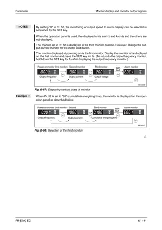
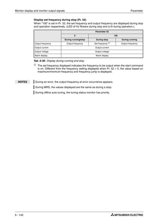
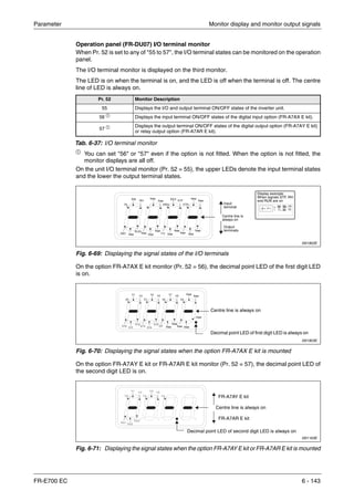
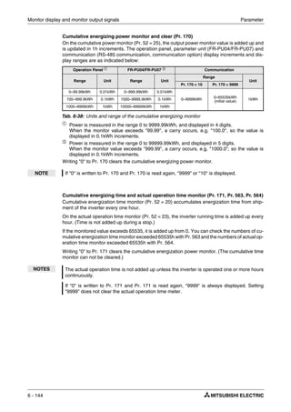
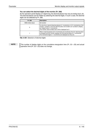
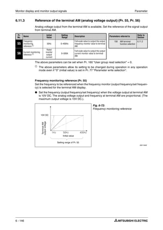
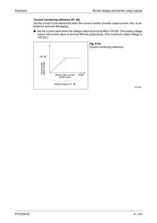
![Monitor display and monitor output signals Parameter
6 - 148
6.11.4 Terminal AM calibration [calibration parameter Pr. 645, C1 (Pr.901)]
By using the operation panel or parameter unit, you can calibrate terminal AM to full scale de-
flection.
The above parameters can be set when Pr. 160 "User group read selection" = 0.
The parameter number in parentheses is the one for use with the operation panel (PA02) for the
FR-E500 series or parameter unit (FR-PU04/FR-PU07).
The above parameters allow its setting to be changed during operation in any operation mode
even if "0" (initial value) is set in Pr. 77 "Parameter write selection".
Terminal AM bias calibration
Use Pr. 645 AM "0V adjustment" to calibrate the bias side output signal from terminal AM. If the
meter needle does not point to 0 when the analog output from terminal AM is 0, add or decrease
the Pr. 645 setting to adjust the meter needle points to 0. When changing ±1 in Pr. 645, the an-
alog output changes about ±5mV. (Analog output will not become lower than about −100mV
even when setting the Pr. 645 lower.)
Pr. No. Name
Initial
Value
Setting
Range
Description Parameters referred to
Refer to
Section
645 AM 0V adjustment 1000 970–1200
Calibrates the scale of the meter when
analog output is 0.
55
56
158
Frequency moni-
toring reference
Current monitor-
ing reference
AM terminal func-
tion selection
6.11.3
6.11.3
6.11.3
C1
(901)
AM terminal calibra-
tion
— —
Calibrates the scale of the meter con-
nected to terminal AM.
Fig. 6-74:
Terminal AM bias calibration
I001931E
NOTES Calibration bias and gain changes when changing the control circuit terminal block. Use
Pr. 645 and C1 (Pr. 901) to calibrate again in that case.
If bias calibration (Pr. 645) is performed, make sure to perform gain calibration (C1 (Pr. 901))
too.
Output
signal
Bias calibration of output
signal (Pr. 645)
Terminal AM
output](https://image.slidesharecdn.com/fr-e700-140613033232-phpapp01/85/Fr-e700-288-320.jpg)
![Parameter Monitor display and monitor output signals
FR-E700 EC 6 - 149
Terminal AM gain calibration [C1 (Pr. 901)]
Terminal AM is factory-set to provide a 10V DC output in the full-scale status of the correspond-
ing monitor item. Calibration parameter C1 (Pr. 901) allows the output voltage ratios (gains) to
be adjusted according to the meter scale. Note that the maximum output voltage is 10V DC, the
maximum output current 1mA.
Calibrate the terminal AM gain in the following procedure:
ቢ Connect an 0–10V DC voltmeter to inverter terminals AM and 5, taking care to correct with
the correct polarity. AM is positive.
ባ Set Pr. 158 to select the monitor signal you want to output to analog output AM (refer to
page 6-146). To display the output frequency or the output current set Pr. 55 or Pr. 56,
respectively, to the maximum frequency or current value for which you want to output 10V
to the terminal.
ቤ Start the frequency inverter in PU mode with the operation panel or the control terminals
(external operation).
ብ Calibrate the full deflection of the meter by setting C1 (Pr. 901) and then operating the digital
dial. Note that the value shown on the operating panel for the monitor signal associated with
C1 does not change when you turn the digital dial, but the analog voltage output to AM will
change as you turn the dial. Confirm the calibration value found by pressing the SET key
(this assigns the maximum voltage output to the displayed value of the monitor signal.)
Fig. 6-75:
Connecting an analog meter to the AM output
I001168C
Fig. 6-76:
Terminal AM gain calibration
I001932E
NOTE If it is not possible output the signal to be measured for calibration at its maximum value you
can set Pr. 158 to "21". This outputs a continuous signal of approx. 10V to terminal AM,
which makes it possible to calibrate the maximum value on the meter. When C1 is used to
calibrate the full meter deflection in this mode a value of "1000" is displayed. Afterwards you
can then reset Pr. 158 to the required monitor signal setting.
10V DC
Output
signal
Gain calibration
of output signal
(Pr. 901)
Terminal AM
output](https://image.slidesharecdn.com/fr-e700-140613033232-phpapp01/85/Fr-e700-289-320.jpg)
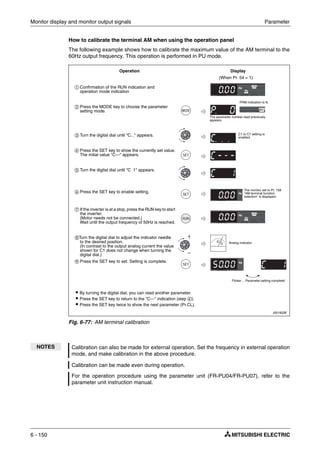
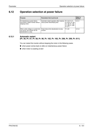
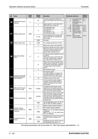
![Parameter Operation selection at power failure
FR-E700 EC 6 - 153
Automatic restart after instantaneous power failure operation (Pr. 30, Pr. 162, Pr. 299)
● Without frequency search
When Pr. 162 = "1" or "11", automatic restart operation is performed in a reduced voltage
system, where the voltage is gradually risen with the output frequency unchanged from prior
to an instantaneous power failure independently of the coasting speed of the motor.
ቢ The output shut off timing differs according to the load condition.
Fig. 6-78:
Automatic restart without frequency search
(Pr. 162 = 1/11)
I001901E
NOTE This system stores the output frequency and rotation direction prior to an instantaneous
power failure and restart using the stored value. Therefore, if the instantaneous power fai-
lure time exceeds 0.2s and the stored value cannot be retained, the inverter starts at Pr. 13
"Starting frequency" (initial value = 0.5Hz) in the starting direction upon power restoration.
Power
supply
(L1, L2, L3)
Motor
speed
[r/min]
Output
frequency
[Hz]
Output
voltage
[V]
Power failure
Coasting time
Pr. 57 Restart cushion
time Pr. 58
ቢ](https://image.slidesharecdn.com/fr-e700-140613033232-phpapp01/85/Fr-e700-293-320.jpg)
![Operation selection at power failure Parameter
6 - 154
● With frequency search
When "0 (initial value) or 10" is set in Pr. 162, the inverter smoothly starts after detecting
the motor speed upon power restoration. (The motor capacity should be equal to or one
rank lower than the inverter capacity.)
When using the frequency search, perform offline autotuning. (Refer to page 6-88 for
advanced magnetic flux vector, general-purpose magnetic flux vector control and page
6-157 for V/f control.)
During reverse rotation, the inverter can be restarted smoothly as the direction of rotation
is detected. You can select whether to make rotation direction detection or not with Pr. 299
"Rotation direction detection selection at restarting". When capacities of the motor and
inverter differ, set "0" (without rotation direction detection) in Pr. 299.
ቢ The output shut off timing differs according to the load condition.
Pr. 299 Setting
Pr. 78 Setting
0 1 2
9999
(Initial value)
With rotation
direction detection
Without rotation
direction detection
Without rotation
direction detection
0
Without rotation
direction detection
Without rotation
direction detection
Without rotation
direction detection
1 With rotation
direction detection
With rotation
direction detection
With rotation
direction detection
Tab. 6-40: Rotation direction direction
Fig. 6-79:
Automatic restart with frequency search
(Pr. 162 = 0/10)
I000722C
Power
supply
(L1, L2, L3)
Motor
speed
[r/min]
Output
frequency
[Hz]
Output
voltage
[V]
Power failure
Coasting time +
speed detection time
Pr. 57
Restart cushion
time Pr. 58
Acceleration time Pr. 611
ቢ](https://image.slidesharecdn.com/fr-e700-140613033232-phpapp01/85/Fr-e700-294-320.jpg)
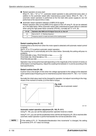
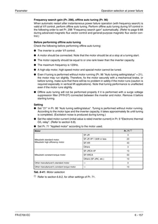
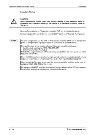
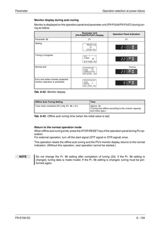
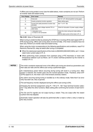
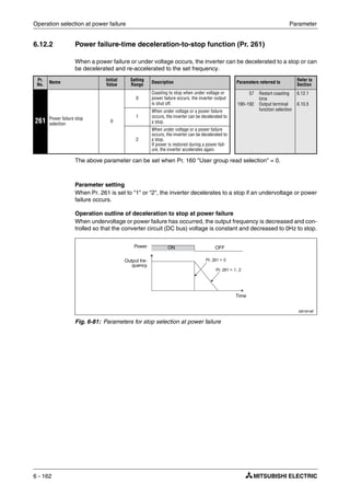
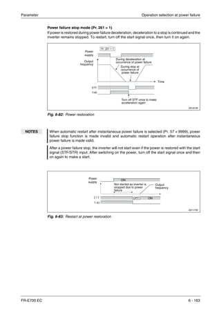
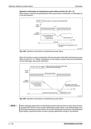
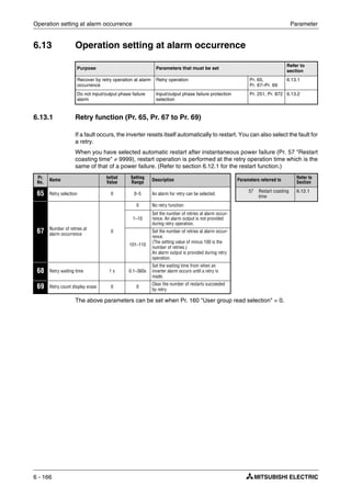
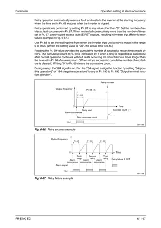
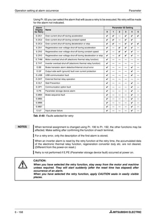
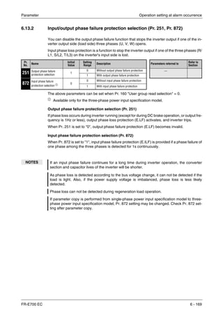
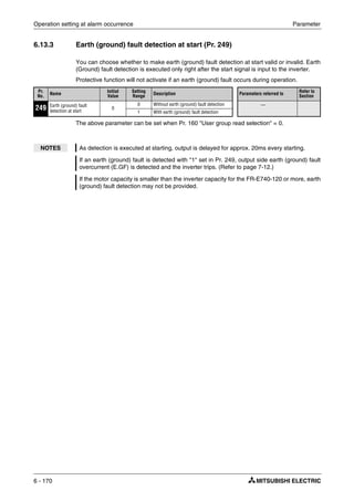
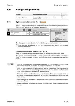
![Motor noise, EMI measures, mechanical resonance Parameter
6 - 172
6.15 Motor noise, EMI measures, mechanical resonance
6.15.1 PWM carrier frequency and soft-PWM control (Pr. 72, Pr. 240)
You can change the motor sound.
The above parameters can be set when Pr. 160 "User group read selection" = 0.
ቢ
The above parameters allow its setting to be changed during operation in any operation
mode even if "0" (initial value) is set in Pr. 77 "Parameter write selection".
PWM carrier frequency changing (Pr. 72)
You can change the PWM carrier frequency of the inverter.
Changing the PWM carrier frequency produces an effect on avoiding the resonance frequency
of a mechanical system or motor or on reducing noise or leakage current generated from the
inverter.
Soft-PWM control (Pr. 240)
Soft-PWM control is a control system that changes the motor noise from a metallic tone into
an unoffending complex tone.
Purpose Parameters that must be set
Refer to
Section
Reduction of the motor noise
Measures against EMI and leakage
currents
Carrier frequency and Soft-PWM selection Pr. 72, Pr. 240 6.15.1
Reduce mechanical resonance Speed smoothing control Pr. 653 6.15.2
Pr.
No. Name
Initial
Value Setting Range Description Parameters referred to
Refer to
Section
72
PWM frequency
selection ቢ 1 0–15
(integral value)
PWM carrier frequency can be
changed. The setting displayed is in
[kHz]. The settings indicate the fol-
lowing frequencies:
0 .............. 0.7kHz
Settings between 1–14 correspond
directly to the frequency values.
15 .......... 14.5kHz
156 Stall prevention
operation selec-
tion
6.3.5
240
Soft-PWM operation
selection ቢ 1
0 Soft-PWM is invalid
1
When Pr. 72 = 0 to 5, Soft-PWM is
valid.
NOTES Decreasing the PWM carrier frequency reduces inverter-generated noise and leakage cur-
rent, but increases motor noise.
When PWM carrier frequency is set to 1kHz or less (Pr. 72 ≤ 1), fast response current limit
may function prior to stall prevention operation due to increase in ripple currents, resulting in
insufficient torque. In such case, set fast-response current limit operation invalid using
Pr. 156 "Stall prevention operation selection".
When setting 2kHz or more in Pr. 72 to perform operation in the place where the ambient
temperature exceeding 40°C, caution should be taken as the rated inverter current should
be reduced. (Refer to appendix A-1.)](https://image.slidesharecdn.com/fr-e700-140613033232-phpapp01/85/Fr-e700-312-320.jpg)
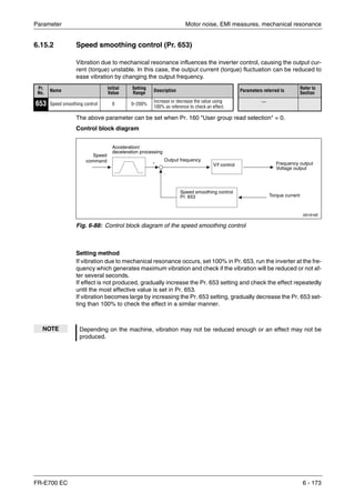
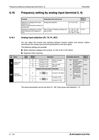
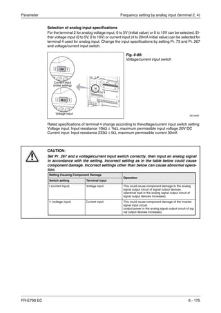
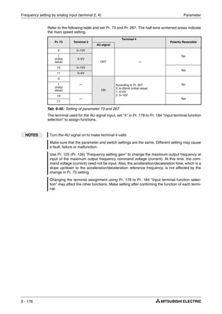
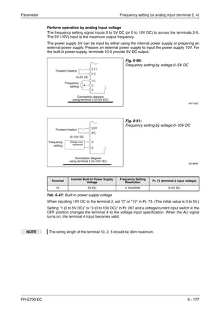
![Frequency setting by analog input (terminal 2, 4) Parameter
6 - 178
Perform operation by analog input current
When the pressure or temperature is controlled constant by a fan, pump, etc., automatic
operation can be performed by inputting the output signal 0/4 to 20mA of the adjuster to across
the terminals 4-5.
Perform forward/reverse rotation by analog input (polarity reversible operation)
Setting "10" or "11" in Pr. 73 and adjusting Pr. 125 (Pr. 126) "Terminal 2 frequency setting gain
frequency" (Terminal 4 frequency setting gain frequency) and C2 (Pr. 902) "Terminal 2
frequency setting bias frequency" to C7 (Pr.905) "Terminal 4 frequency setting gain" makes
reverse operation by terminal 2 (terminal 4) valid.
NOTE The AU signal must be turned on to use the terminal 4. For the terminal used for AU signal
input, set "4" in any of Pr. 178 to Pr. 184 to assign the function.
Fig. 6-92:
Frequency setting by the function "Current
input 0/4–20mA" assigned to terminal 4
I001184E
Example Ĥ When performing reversible operation by terminal 2 (0 to 5V) input.
ቢ Set "11" in Pr. 73 to make reversible operation valid.
Set frequency at maximum analog input in Pr. 125 (Pr. 903).
ባ Set 1/2 of the value set in C4 (Pr. 903) in C3 (Pr. 902).
ቤ Reversible operation is performed when 0 to 2.5V DC is input and forward rotation when
2.5 to 5V DC.
Ħ
P
CAUTION:
When reversible operation is set, be aware of reverse rotation operation when analog
input stops (only the start signal is input).
NOTE When reversible operation is valid, reversible operation (0 to 4mA: reverse operation, 4mA
to 20mA: forward operation) is performed by terminal 4 in the initial setting.
Forward rotation
Frequency
setting
0/4–20mA DC
Connection diagram
using terminal 4 (0/4–20mA DC)
Current
input
equipment
Forward
rotation
Not reversible
Reverse
rotation
Reversible
Terminal 2 input [V]
Set frequency [Hz]](https://image.slidesharecdn.com/fr-e700-140613033232-phpapp01/85/Fr-e700-318-320.jpg)
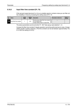
![Frequency setting by analog input (terminal 2, 4) Parameter
6 - 180
6.16.3 Bias and gain of frequency setting voltage (current) [Pr. 125, Pr. 126,
Pr. 241, C2 (Pr. 902) to C7 (Pr. 905)]
You can set the magnitude (slope) of the output frequency as desired in relation to the frequency
setting signal (0 to 5V, 0 to 10V or 0/4 to 20mA DC).
These parameters can be used to configure the inverter precisely for set point signals that either
exceed or do not quite reach 5V or 10V or 20mA. These settings can also be used to configure
inverse control (i.e. high output frequency at minimum set point signal, minimum output
frequency at maximum set point signal).
ቢ The above parameters can be set when Pr. 160 "User group read selection" = 0.
ባ
The parameter number in parentheses is the one for use with the operation panel (PA02)
for the FR-E500 series or parameter unit (FR-PU04/FR-PU07).
ቤ The above parameter allow its setting to be changed during operation in any operation mode
even if "0" (initial value) is set in Pr. 77 "Parameter write selection".
Pr. No. Name
Initial
Value
Setting
Range
Description Parameters referred to
Refer to
Section
125 Terminal 2 frequency setting
gain frequency
50Hz 0–400Hz
Set the frequency of terminal 2
input gain (maximum).
20
73
267
79
Acceleration/
deceleration
reference
frequency
Analog input
selection
Terminal 4 input
selection
Operation mode
selection
6.7.1
6.16.1
6.16.1
6.18.1
126 Terminal 4 frequency setting
gain frequency
50Hz 0–400Hz
Set the frequency of terminal 4
input gain (maximum).
241 Analog input display unit
switchover ቢ ቤ 0
0 Displayed in %
Select the unit of
analog input
display.1
Displayed in
V/mA
C2
(902)
Terminal 2 frequency setting
bias frequency ቢ ባ 0Hz 0–400Hz
Set the frequency on the bias side
of terminal 2 input.
C3
(902)
Terminal 2 frequency setting
bias ቢ ባ 0% 0–300%
Set the converted % of the bias
side voltage (current) of terminal
2 input.
C4
(903)
Terminal 2 frequency setting
gain ቢ ባ 100% 0–300%
Set the converted % of the gain
side voltage of terminal 2 input.)
C5
(904)
Terminal 4 frequency setting
bias frequency ቢ ባ 0Hz 0–400Hz
Set the frequency on the bias side
of terminal 4 input.
C6
(904)
Terminal 4 frequency setting
bias ቢ ባ 20% 0–300%
Set the converted % of the bias
side current (voltage) of terminal
4 input.
C7
(905)
Terminal 4 frequency setting
gain ቢ ባ 100% 0–300%
Set the converted % of the gain
side current (voltage) of terminal
4 input.](https://image.slidesharecdn.com/fr-e700-140613033232-phpapp01/85/Fr-e700-320-320.jpg)
![Parameter Frequency setting by analog input (terminal 2, 4)
FR-E700 EC 6 - 181
Change the frequency at maximum analog input (Pr. 125, Pr. 126)
Set a value to Pr. 125 (Pr. 126) when changing only the frequency setting (gain) of the maximum
analog input power (current). (C2 (Pr. 902) to C7 (Pr. 905) setting need not be changed.)
Analog input bias/gain calibration [C2 (Pr. 902) to C7 (Pr. 905)]
The parameters for input bias and gain can be used to configure the inverter for set point signals
that do not exactly match 5V or 10V or 20mA. You can enter the exact output frequencies to
be associated with the minimum and maximum signal values separately for terminals 2 and 4.
This feature can also be used to configure an inverse control characteristic (i.e. high output
frequency at minimum set point signal, minimum output frequency at maximum set point signal).
Set the bias frequency of the terminal 2 input using C2 (Pr. 902). (Factory-set to the frequency
at 0V.)
Parameter C3 (Pr. 902) is the frequency setting bias for the input signal at terminal 2, i.e. the
minimum value of the analog signal. When signals are smaller than this value the frequency
set point signal will be limited to the value set with C2.
Parameter 125 sets the gain for the terminal 2 output frequency. This is the frequency set point
value that corresponds to the maximum analog signal defined with Pr. 73. (Pr. 125 is set to a
default value of 50Hz at the factory.)
Parameter C4 (Pr. 903) sets the gain for the input signal on terminal 2, i.e. the maximum value
of the analog signal connected to terminal 2. When signals exceed this value the frequency set
point value is limited to the value stored in Pr. 125.
Parameter C5 (Pr. 904) sets the frequency set point bias frequency for terminal 4. This is the
frequency corresponding to the minimum analog signal. (This parameter is set to a default value
of 0Hz at the factory.)
Parameter C6 (Pr. 904) sets the bias of the input signal on terminal 4, i.e. the minimum value
of the analog signal connected to terminal 4. When the signal on this terminal is lower than this
value the frequency set point value is limited to the value set with C5. (This parameter is set to
a default value of 20% at the factory, which corresponds to approx. 4mA.)
Parameter 126 sets the gain for the terminal 4 output frequency. This is the frequency set point
value that corresponds to the maximum analog signal defined with Pr. 73. (Pr. 126 is set to a
default value of 50Hz at the factory.)
Parameter C7 (Pr. 905) sets the gain of the input signal on terminal 4, i.e. the maximum value
of the analog signal connected to terminal 4. When the signal on this terminal is higher than
this value the frequency set point value is limited to the value set with Pr. 126.](https://image.slidesharecdn.com/fr-e700-140613033232-phpapp01/85/Fr-e700-321-320.jpg)
![Frequency setting by analog input (terminal 2, 4) Parameter
6 - 182
There are three methods to adjust the frequency setting voltage (current) bias/gain:
● Method to adjust any point by application of voltage (current) to across the terminals 2-5
(4-5). (Refer to page 6-184.)
● Method to adjust any point without application of a voltage (current) to across terminals 2-5
(4-5). (Refer to page 6-185.)
● Adjusting only the frequency without adjusting the voltage (current).
(Refer to page 6-186.)
I001191E
Fig. 6-93: Signal adjustment of terminal 2
I001191E
Fig. 6-94: Signal adjustment of terminal 4
NOTE When voltage/current input signal for terminal 4 was switched using Pr. 267 and voltage/cur-
rent input switch, perform calibration without fail.
Frequency setting signal
Outputfrequency[Hz]
0
0
0
C3 (Pr. 902)
100%
5V
10V
C4 (Pr. 903)
Gain Pr. 125
Initial value
Bias
50Hz
C2
(Pr. 902)
Frequency setting signal
Outputfrequency[Hz]
0
0
C6 (Pr. 904)
100%
20mA
C7 (Pr. 905)
Gain Pr. 126
Initial value
Bias
50Hz
C5
(Pr. 904)](https://image.slidesharecdn.com/fr-e700-140613033232-phpapp01/85/Fr-e700-322-320.jpg)
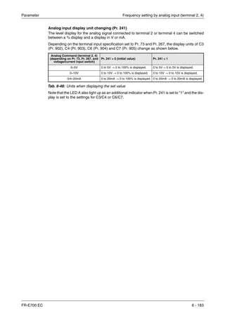
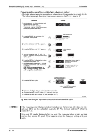
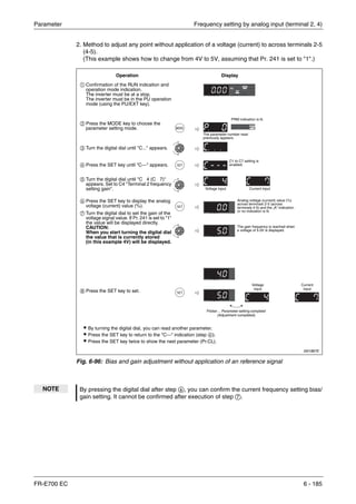
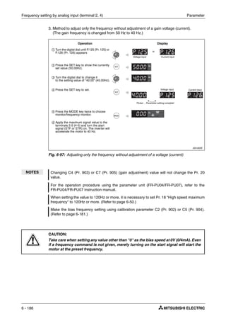
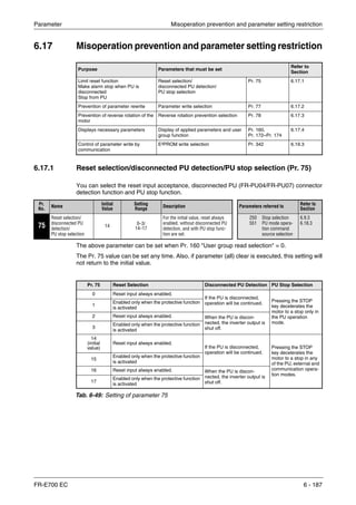
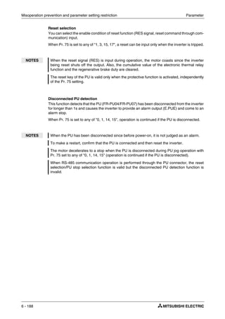
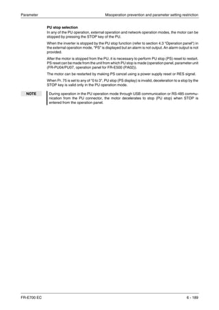
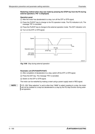
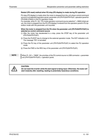
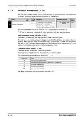
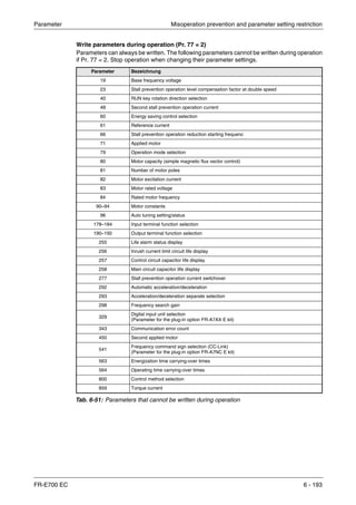
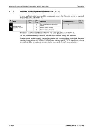
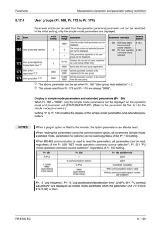
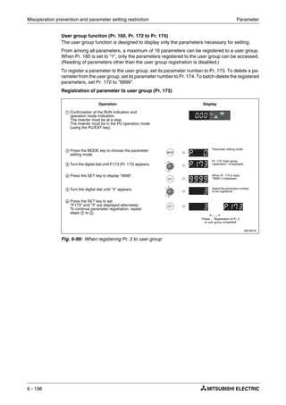
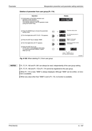
![Selection of operation mode and operation location Parameter
6 - 198
6.18 Selection of operation mode and operation location
6.18.1 Operation mode selection (Pr. 79)
Used to select the operation mode of the inverter.
Mode can be changed as desired between operation using external command signals (external
operation), operation from the operation panel and PU (FR-PU07/FR-PU04) (PU operation),
combined operation of PU operation and external operation (external/PU combined operation),
and network operation (when RS-485 communication or acommunication option is used).
The above parameter can be changed during a stop in any operation mode.
Purpose Parameters that must be set
Refer to
Section
Operation mode selection Operation mode selection Pr. 79 6.18.1
Started in network operation mode Operation mode at power on Pr. 79, Pr. 340 6.18.2
Selection of control source Selection of control source, speed com-
mand source and control location during
communication operation
Pr. 338, Pr. 339,
Pr. 550, Pr. 551
6.18.3
Pr.
No.
Name Initial
Value
Setting
Range
Description Parameters referred to Refer to
Section
79 Operation mode
selection
0
0
External/PU switchover mode
External operation mode at power on
15
4–6
24–27
232–239
75
161
178–184
190–192
340
550
Jog frequency
Multi-speed
operation
Reset selection/
disconnected PU
detection/
PU stop selection
Frequency setting/
key lock operation
selection
Input terminal func-
tion selection
Output terminal
function selection
Communication
start-up mode
selection
NET mode opera-
tion command
source selection
6.6.2
6.6.1
6.17.1
6.22.3
6.10.1
6.10.5
6.18.2
6.18.3
1 Fixed to PU operation mode
2
Fixed to external operation mode
Operation can be performed by switching
between external and NET operation
mode
3
Combined operation mode 1
Running frequency:
Operation panel, and PU (FR-PU04/
FR-PU07) setting or external signal input
[multi-speed setting, across terminals
4-5 (valid when AU signal turns on)]
Start signal:
External signal input (terminal STF, STR)
4
External/PU combined operation mode 2
Running frequency:
External signal input (terminal 2, 4, JOG,
multi-speed setting, etc.)
Start signal:
Enter from the RUN key of the operation
panel and the FWD/REV keys of the PU
(FR-PU04/FR-PU07)
6
Switchover mode
Switchover between PU operation, exter-
nal operation, and NET operation is avail-
able while keeping the same operation
status.
7
External operation mode (PU operation
interlock)
X12 signal ON:
Operation mode can be shifted to PU
operation mode (output stop during
external operation)
X12 signal OFF:
Operation mode can not be switched to
PU operation mode.](https://image.slidesharecdn.com/fr-e700-140613033232-phpapp01/85/Fr-e700-338-320.jpg)
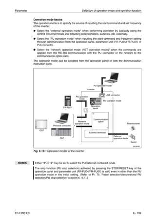
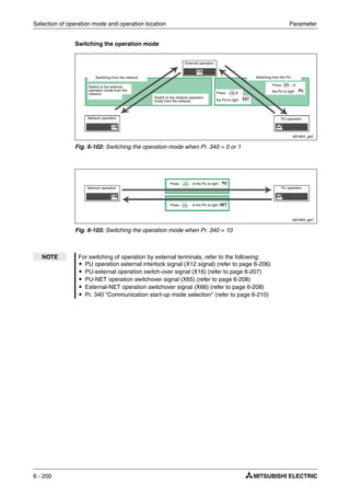
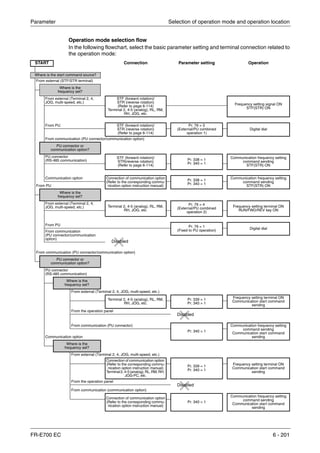
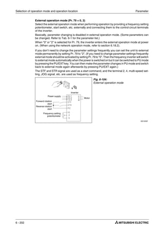
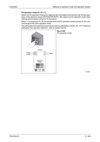
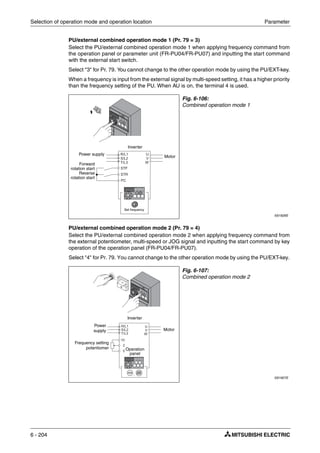
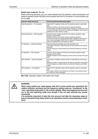
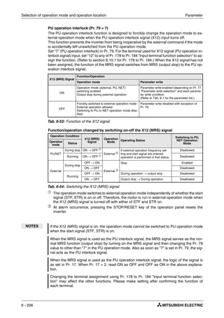
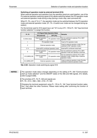
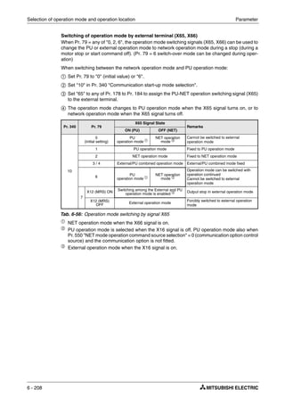
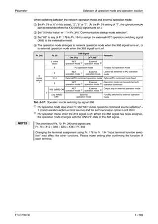
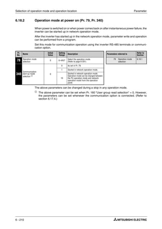
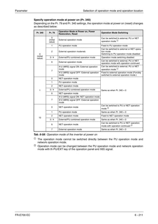
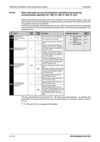
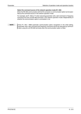
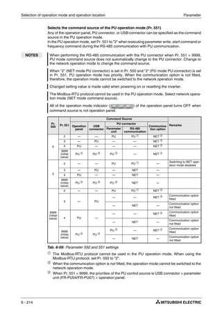
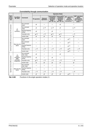
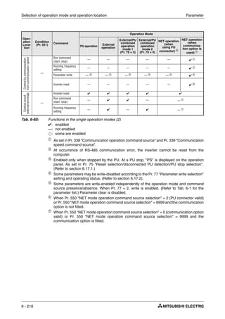
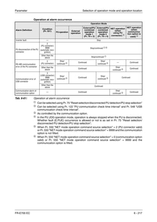
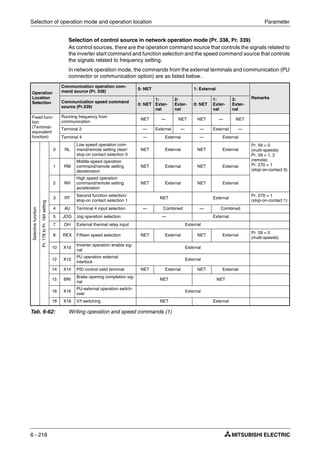
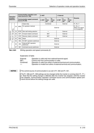
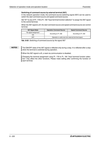
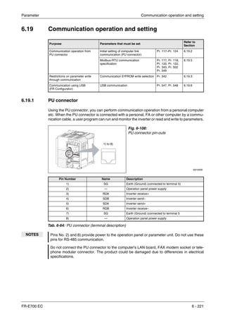
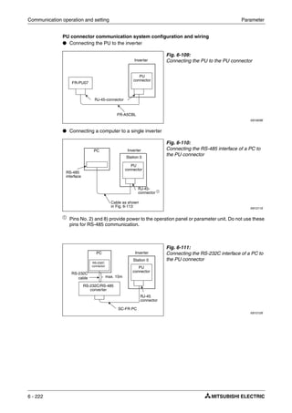
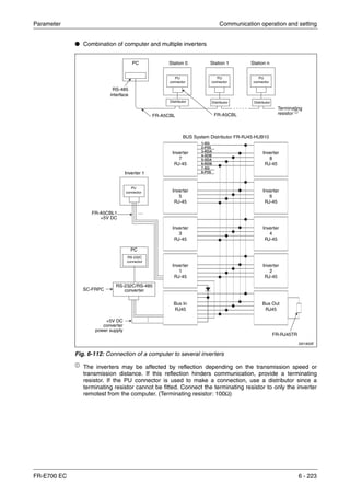
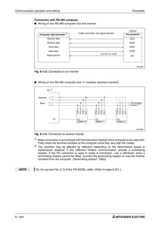
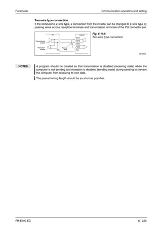
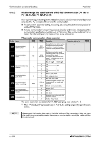
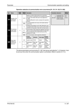
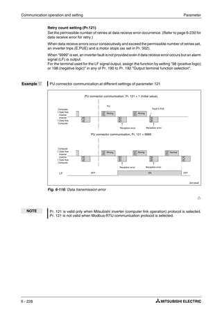
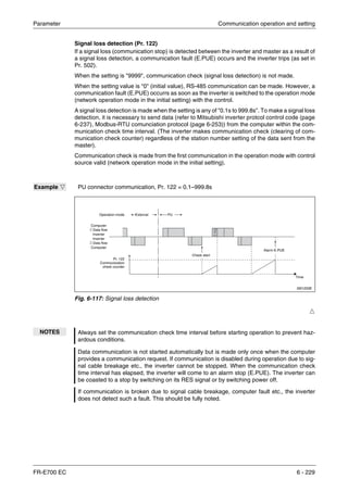
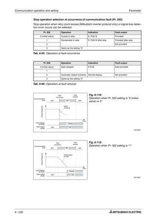
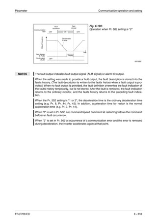
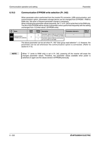
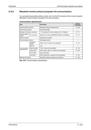
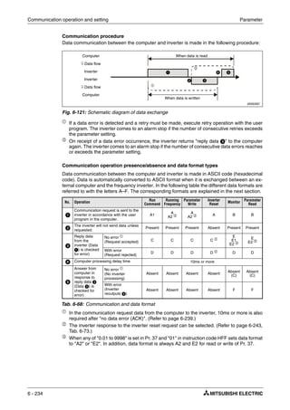
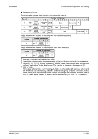
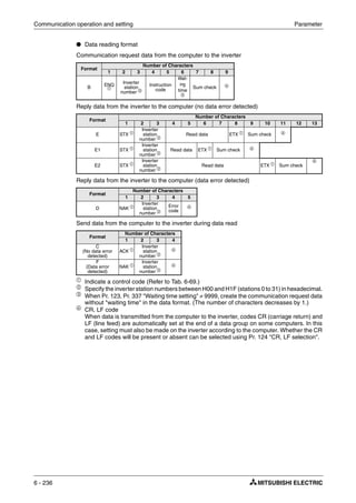
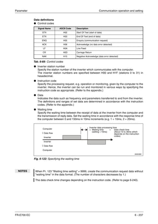
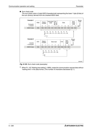
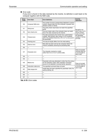
![Communication operation and setting Parameter
6 - 240
● Response time
Formula for data sending time:
ቢ
The communication specifications are listed in the table below:
The data check time related to different functions is shown in the table below:
I001327E
Fig. 6-124: Response time
Data
sending time [s] =
1
×
Number of data
characters
(refer to page 6-234)
×
Communications specifications
(total number of bits) ቢ
Communication speed
(Baudrate)
Name Number of Bits
Stop bit length 1 bit
2 bits
Data length 7 bit
8 bits
Parity check Yes 1 bit
No 0 bits
Tab. 6-71: Communication specifications
NOTES In addition to the above, 1 start bit is necessary.
Minimum number of total bits: 9 bits. Maximum number of total bits: 12 bits.
Function Data Check Time
Various monitors, run command, frequency setting
(RAM)
< 12ms
Parameter read/write, frequency setting (E²PROM) < 30ms
Parameter clear/all clear < 5s
Reset command — (no answer)
Tab. 6-72: Data check time
Computer
⇓ Data flow
Inverter
Inverter
⇓ Data flow
Computer
Data sending time (Refer to the following formula)
Inverter data processing time = Waiting time + Data check time
(setting × 10ms) (Depends on the
instruction code
(see Tab. 6-72))
Time
Data sending time (Refer to the following formula)
10ms or more necessary](https://image.slidesharecdn.com/fr-e700-140613033232-phpapp01/85/Fr-e700-380-320.jpg)
![Parameter Communication operation and setting
FR-E700 EC 6 - 241
Instructions for the program
When data from the computer has any error, the inverter does not accept that data. Hence, in
the user program, always insert a retry program for data error.
All data communication, e.g. run command or monitoring, are started when the computer gives
a communication request. The inverter does not return any data without the computer's request.
Hence, design the program so that the computer gives a data read request for monitoring, etc.
as required.
Program example
To change the operation mode to computer link operation
Programming example of Microsoft®
Visual C++®
(Ver.6.0)
Fig. 6-125:Programming example
#include <stdio.h>
#include <windows.h>
void main(void){
HANDLE hCom; //Communication handle
DCB hDcb; //Structure for communication setting
COMMTIMEOUTS hTim; //Structure for time out setting
char szTx[0x10]; //Send buffer
char szRx[0x10]; //Receive buffer
char szCommand[0x10]; //Command
int nTx,nRx; //For buffer size storing
int nSum; //For sum code calculation
BOOL bRet;
int nRet;
int i;
//**** Opens COM1 Port****
hCom = CreateFile ("COM1", (GENERIC_READ | GENERIC_WRITE), 0, NULL, OPEN_EXISTING, FILE_ATTRIBUTE_NORMAL, NULL);
if (hCom != NULL) {
//**** Makes a communication setting of COM1 port****
GetCommState(hCom,&hDcb); //Retrieves current communication information
hDcb.DCBlength = sizeof(DCB); //Structure size setting
hDcb.BaudRate = 19200; //Communication speed=19200bps
hDcb.ByteSize = 8; //Data length=8bit
hDcb.Parity = 2; //Even parity
hDcb.StopBits = 2; //Stop bit=2bit
bRet = SetCommState(hCom,&hDcb); //Sets the changed communication data
if (bRet == TRUE) {
//**** Makes a time out setting of COM1 port****
Get CommTimeouts(hCom,&hTim); /Obtains the current time out value
hTim.WriteTotalTimeoutConstant = 1000; //Write time out 1s
hTim.ReadTotalTimeoutConstant = 1000; //Read time out 1s
SetCommTimeouts(hCom,&hTim); //Changed time out value setting
//**** Sets the command to switch the operation mode of the station 1 inverter to the network operation mode ****
sprintf(szCommand,"01FB10000"); //Send data (NET operation write)
nTx = strlen(szCommand); //Send data size
//**** Generates sum code****
nSum = 0; //Initialization of sum data
for (i = 0;i < nTx;i++) {
nSum += szCommand[i]; //Calculates sum code
nSum &= (0xff); //Masks data
}
//**** Generates send data****
memset(szTx,0,sizeof(szTx)); //Initialization of send buffer
memset(szRx,0,sizeof(szRx)); //Initialization of receive buffer
sprintf(szTx,"5%s%02X",szCommand,nSum); //ENQ code+send data+sum code
nTx = 1 + nTx + 2; //Number of ENQ code+number of send data+number of sum code
nRet = WriteFile(hCom,szTx,nTx,&nTx,NULL);
//**** Sending ****
if(nRet != 0) {
nRet = ReadFile(hCom,szRx,sizeof(szRx),&nRx,NULL);
//**** Receiving ****
if(nRet != 0) {
//**** Displays the receive data ****
for(i = 0;i < nRx;i++) {
printf("%02X ",(BYTE)szRx[i]); //Consol output of receive data
//Displays ASCII coder in hexadecimal. Displays 30 when "0"
}
printf("nr");
}
}
}
CloseHandle(hCom); //Close communication port
}
}](https://image.slidesharecdn.com/fr-e700-140613033232-phpapp01/85/Fr-e700-381-320.jpg)
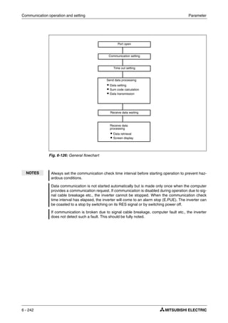
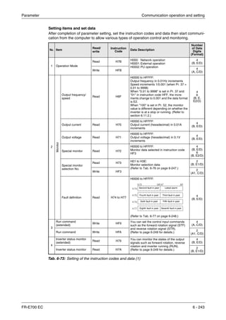
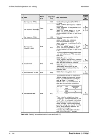
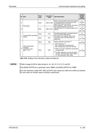
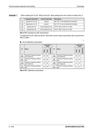
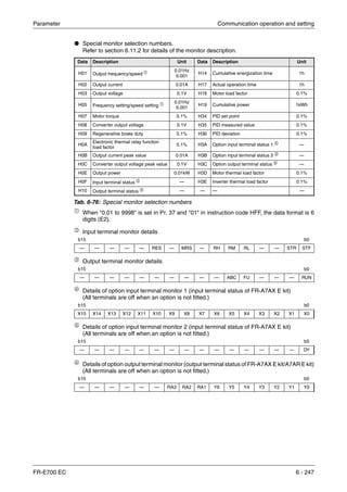
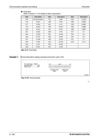
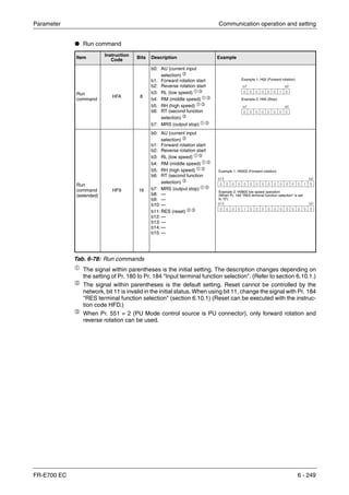
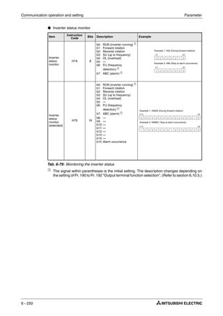
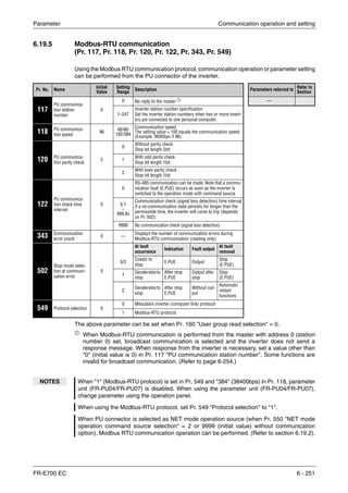
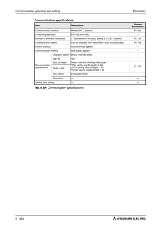
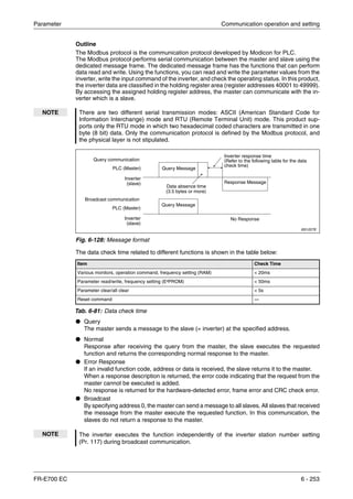
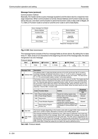
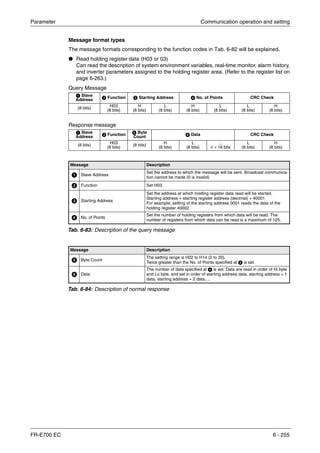
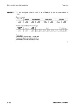
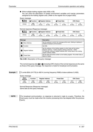
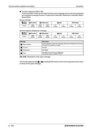
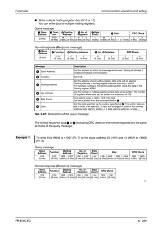
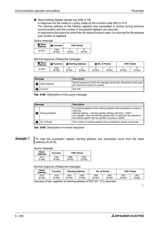
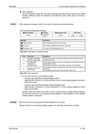
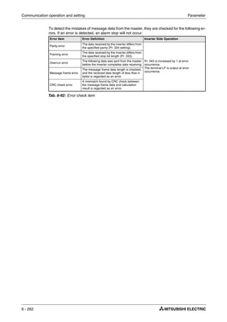
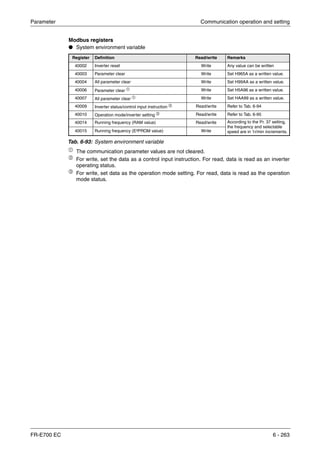
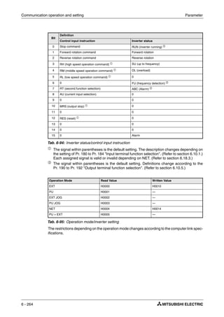
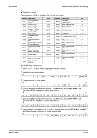
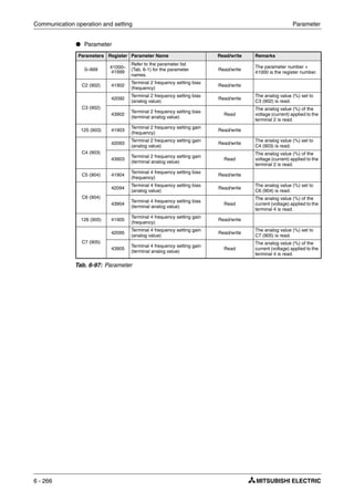
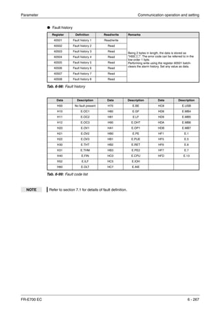
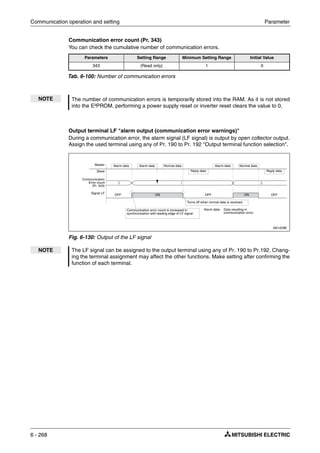
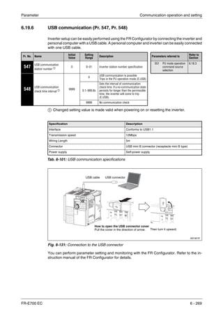
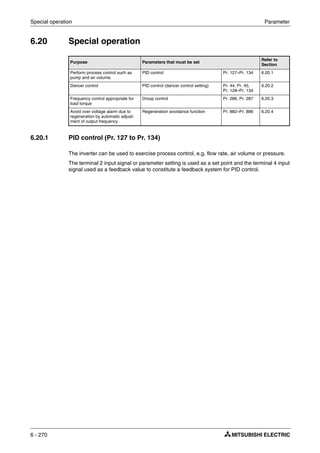
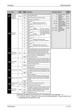
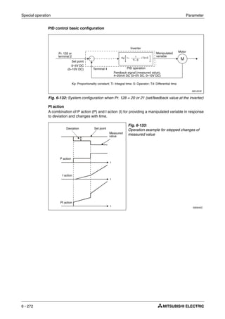
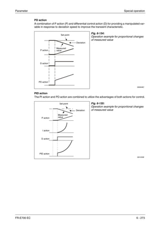
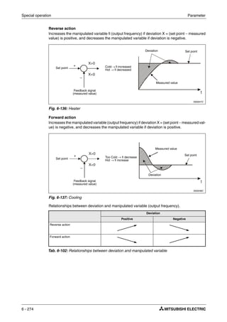
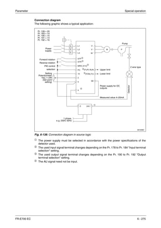
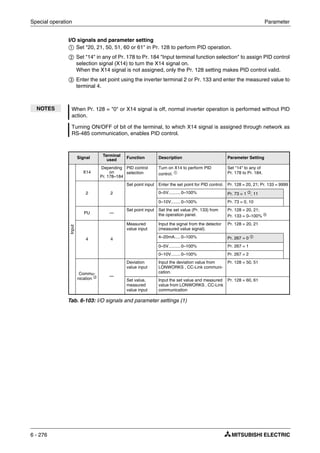
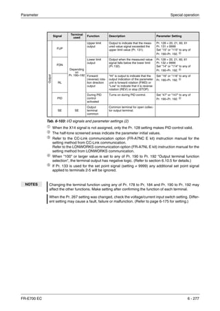
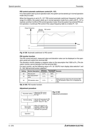
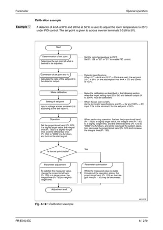
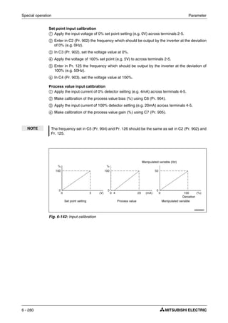
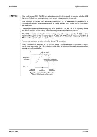
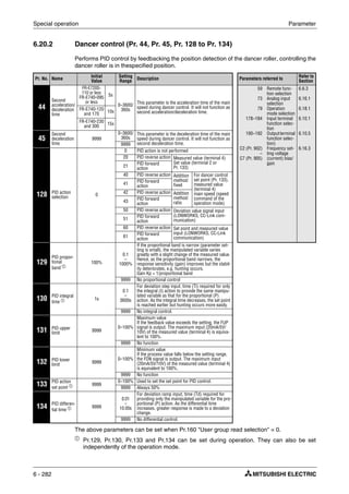
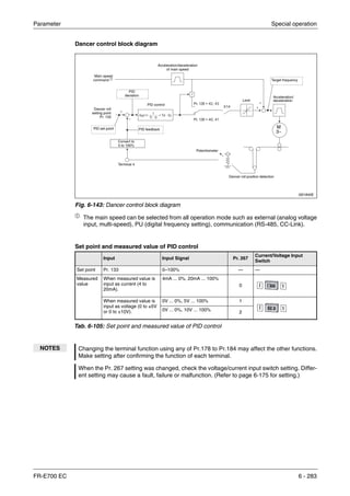
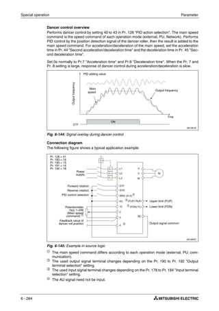
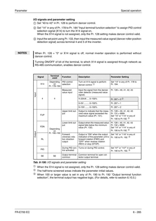
![Parameter Special operation
FR-E700 EC 6 - 287
Parameter details
When ratio (Pr. 128 = 42, 43) is selected for addition method, PID control × (ratio of main speed)
is added to the main speed. The ratio is determined by the Pr. 125 "Terminal 2 frequency setting
gain frequency" and C2 (Pr. 902) "Terminal 2 frequency setting bias frequency". The frequency
setting signal is set to 0 to 50Hz in the range between 0 to 100% in the initial setting. The ratio
is (× 100%) when the main speed is 50Hz and (× 50%) when 25Hz.
Turning X14 signal on/off during operation by assigning X14 signal results in the following op-
eration.
When X14 signal is on: Uses output frequency unchanged as the main speed command and
continues operation by dancer control.
When X14 signal is off: Ends dancer control and continues operation at the set frequency
made valid.
Action of Pr. 129 "PID proportional band", Pr. 130 "PID integral time", Pr. 131 "PID upper limit",
Pr. 132 "PID lower limit", Pr. 134 "PID differential time is the same as PID control. For the re-
lationship of controlled variable (%) of PID control and frequency, 0% is equivalent to the set fre-
quency of Pr. 902 and 100% to Pr. 903.
For the Pr. 133 "PID action set point" setting, set frequency of Pr. 902 is equivalent to 0% and
Pr. 903 to 100%. When 9999 is set in Pr. 133, 50% is the set point.
I001894E
Fig. 6-146: Signal calibration at terminal 2
NOTES Even when C4 (Pr. 903) is set to other than 100%, the frequency setting signal is considered
as 100%.
Even when C3 (Pr. 903) is set to other than 0%, the frequency setting signal is considered
as 0%.
When C2 (Pr .902) is set to other than 0Hz, the frequency setting signal is 0% when C2
(Pr. 902) is less than the set frequency.
Pr. 128 PID Action
Addition
Method
Set Point Measured Value Main Speed Command
40 Reverse action
Fixed
Pr. 133 Terminal 4
Speed command for each
operation mode
41 Forward action
42 Reverse action
Ratio
43 Forward action
Tab. 6-107: PID control in dependence of parameter 128
NOTE Pr. 127 "PID control automatic switchover frequency" is invalid.
Frequency setting signals
Outputfrequency[Hz]
0 100%
Initial value
Bias
50Hz
C2
(Pr. 902)
Gain Pr. 125](https://image.slidesharecdn.com/fr-e700-140613033232-phpapp01/85/Fr-e700-427-320.jpg)
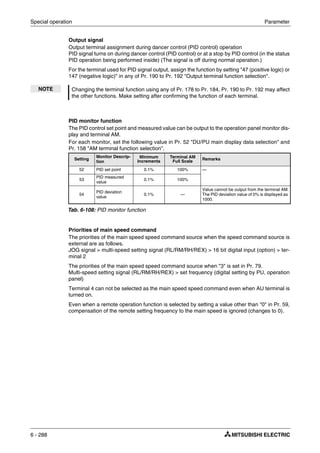
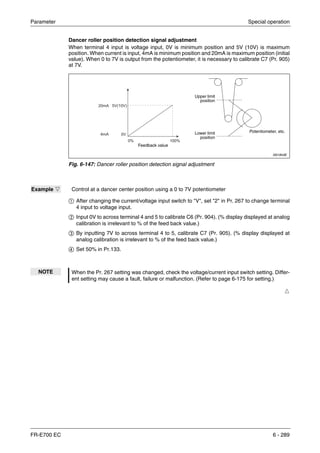
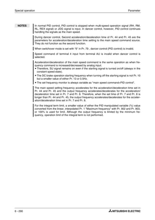
![Parameter Special operation
FR-E700 EC 6 - 291
6.20.3 Droop control (Pr. 286 to Pr. 287)
This function is designed to balance the load in proportion to the load torque to provide the speed
drooping characteristic under advanced magnetic flux vector control. This function is effective
for balancing the load when using multiple inverters.
The output frequency is changed according to the magnitude of torque current under advanced
magnetic flux vector control. The drooping amount at the rated torque is set by the droop gain
as a percentage using the rated frequency as a reference.
The maximum droop compensation frequencyis 120Hz.
Pr. No. Name
Initial
Value
Setting
Range
Description Parameters referred to
Refer to
Section
286 Droop gain 0%
0
Droop control is invalid
(Normal operation)
1 Maximum frequency
PID control
6.4.1
6.20.1
0.1–100%
Droop control is valid
Drooping amount at the rated
torque as a percentage with
respect to the rated motor fre-
quency.
287 Droop filter time constant 0.3s 0–1s
Time constant of the filter
applied on the torque current.
I001627E
Fig. 6-148: Droop control
NOTES Set the droop gain to about the rated slip of the motor.
Droop control is invalid during PID control operation.
The maximum value of frequency after droop compensation is either 120Hz or Pr. 1 "Maxi-
mum frequency", whichever is smaller.
AD MFVCAD MFVCAD MFVC
Ratedfrequency
0 100%−100%
Frequency
command
Droop compensation
frequency
Droop
gain
Torque
Droop compensation frequency
Torque current after filtering
Rated value of base frequency
--------------------------------------------------------------------------------- Rated motor frequency Droop gain×
100
------------------------------------------------------------------------------------------------×=
Rated slip
Synchronous speed at base frequency Rated speed–
Synchronous speed at base frequency
---------------------------------------------------------------------------------------------------------------------------------------------- 100 [%]×=](https://image.slidesharecdn.com/fr-e700-140613033232-phpapp01/85/Fr-e700-431-320.jpg)
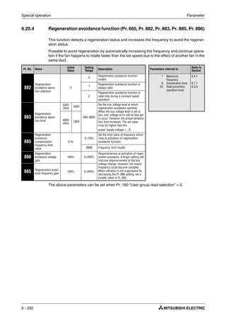
![Parameter Special operation
FR-E700 EC 6 - 293
What is regeneration avoidance function? (Pr. 882, Pr. 883)
When the regeneration status is serious, the DC bus voltage rises and an over voltage alarm
(E.OV२) may occur. When this bus voltage rise is detected and the bus voltage level reaches
or exceeds Pr. 883, increasing the frequency avoids the regeneration status.
The regeneration avoidance function is always on when "1" is set in Pr. 882 and activated only
during a constant speed when "2" is set in Pr. 882.
I001257E
Fig. 6-149: Regeneration avoidance function
NOTES The inclination of the frequency increased or decreased by the regeneration avoidance func-
tion changes depending on the regeneration status.
The DC bus voltage of the inverter is normally about √2 times greater than the input voltage
(when the input voltage is 220 V, the bus voltage is about 311 V DC and when the input volt-
age is 440V AC, the bus voltage is about 622V DC). However, it varies with the input power
supply waveform.
The Pr. 883 setting should be kept higher than the DC bus voltage level. Otherwise, the
regeneration avoidance function is always on.
While over voltage stall (oL) stops the output frequency during deceleration, the regenera-
tion avoidance function is always on and increases the frequency according to the regenera-
tion amount.
Busvoltage
[VDC]
Output
frequency[Hz]
Regeneration avoidance operation
example for acceleration
Regeneration avoidance operation
example for constant speed
Regeneration avoidance operation
example for deceleration
Pr. 883Pr. 883 Pr. 883
During regeneration avoidance
function operation
During regeneration avoidance
function operation During regeneration avoidance
function operation
Time
Time
Time
Busvoltage
[VDC]
Output
frequency[Hz]
Busvoltage
[VDC]
Output
frequency[Hz]](https://image.slidesharecdn.com/fr-e700-140613033232-phpapp01/85/Fr-e700-433-320.jpg)
![Special operation Parameter
6 - 294
Limit regeneration avoidance operation frequency (Pr. 885)
You can limit the output frequency compensated for (increased) by the regeneration avoidance
function.
The frequency is limited to the output frequency (frequency prior to regeneration avoidance op-
eration) + Pr. 885 "Regeneration avoidance compensation frequency limit value" during accel-
eration or constant speed. If the regeneration avoidance frequency exceeds the limit value dur-
ing deceleration, the limit value is held until the output frequency falls to 1/2 of Pr. 885.
When the regeneration avoidance frequency has reached Pr. 1 "Maximum frequency", it is lim-
ited to the maximum frequency.
When Pr. 885 is set to "9999", the frequency setting is invalid.
Regeneration avoidance function adjustment (Pr. 665, Pr. 886)
If the frequency becomes instable during regeneration avoidance operation, decrease the set-
ting of Pr. 886 "Regeneration avoidance voltage gain". Reversely, if sudden regeneration caus-
es an overvoltage alarm, increase the setting.
When vibration is not suppressed by decreasing the Pr. 886 setting, set a smaller value in
Pr. 665 "Regeneration avoidance frequency gain".
Fig. 6-150:
Limit the output frequency
I001260E
NOTES When regeneration avoidance operation is performed, "oL" (over voltage stall) is displayed
and the OL signal is output.
When regeneration avoidance operation is performed, stall prevention is also activated at
the same time.
The regeneration avoidance function cannot shorten the actual deceleration time taken to
stop the motor. The actual deceleration time depends on the regeneration energy consump-
tion capability. When shortening the deceleration time, consider using the regeneration unit
(FR-BU2, FR-CV, FR-HC) and brake resistor (MRS, FR-ABR etc.) to consume regeneration
energy at constant speed.
When using the regeneration unit (FR-BU2, FR-CV, FR-HC) and brake resistor (FR-ABR
etc.), set Pr. 882 to "0 (initial value)" (regeneration avoidance function invalid). When using
the regeneration unit, etc. to consume regeneration energy at deceleration, set Pr. 882 to "2"
(regeneration avoidance function valid only at a constant speed).
When regeneration avoidance operation is performed, the OL signal output item of Pr. 156
also becomes the target of oL (over voltage stall). Pr. 157 "OL signal output timer" also
becomes the target of (over voltage stall).
Output
frequency[Hz]
Output frequency
Time
Pr. 885/2
Restriction level
Pr. 885](https://image.slidesharecdn.com/fr-e700-140613033232-phpapp01/85/Fr-e700-434-320.jpg)
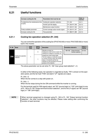
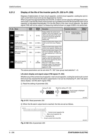
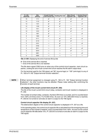
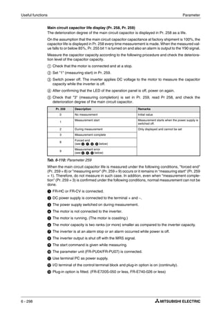
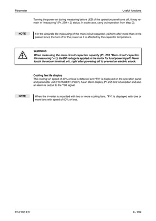
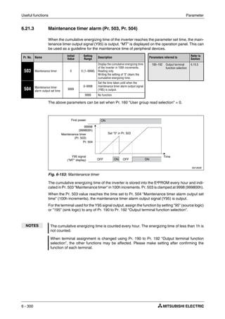
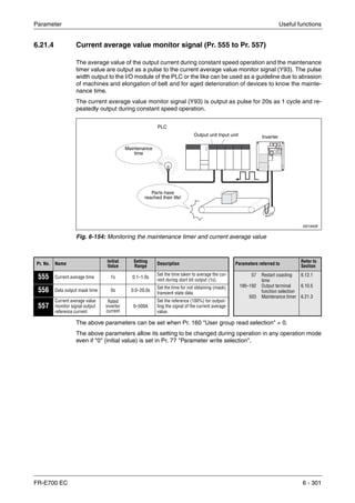
![Useful functions Parameter
6 - 302
The pulse output of the current average value monitor signal (Y93) is shown below.
For the terminal used for the Y93 signal output, assign the function by setting "93" (positive logic)
or "193" (negative logic) to Pr. 190 "RUN terminal function selection". The function can not be
assigned to Pr. 192 "ABC terminal function selection".
Setting of Pr. 556 "Data output mask time"
The output current is unstable (transient state) right after the operation is changed from the ac-
celeration/deceleration state to the constant speed operation. Set the time for not obtaining
(mask) transient state data in Pr. 556.
I001265E
Fig. 6-155: Output of the pulse signal Y93
From acceleration to constant speed operationOutput frequency
Y93
Data output mask time
When the speed has changed to constant from
acceleration/deceleration, Y93 signal is not output
for Pr. 556 time.
Start pulse
Output as Hi pulse shape for 1s (fixed)
Time and output current set in Pr. 555 are averaged
Output current average value pulse
The averaged current value is output as low pulse shape for 0.5
to 9s (10 to 180%) during start bit output
. Signal output time
Output current average value [A]
Pr. 557 [A]
-------------------------------------------------------------------------------------- 5s×=
Maintenance timer pulse
The maintenance timer value (Pr.503) is output as Hi
output pulse shape for 2 to 9s (16000h to 72000h).
Signal output time
Pr. 503 1000h×
40000h
------------------------------------------ 5s×=
End pulse
output as low pulse shape
for 1 to 16.5s
1 cycle (20s) Next cycle
Time](https://image.slidesharecdn.com/fr-e700-140613033232-phpapp01/85/Fr-e700-442-320.jpg)
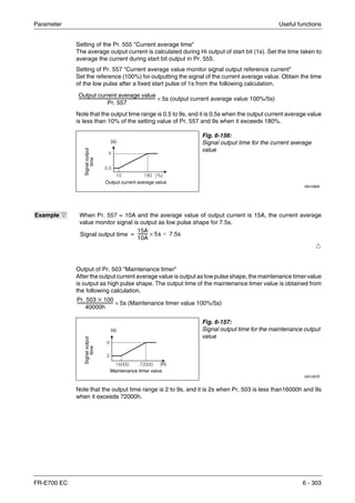
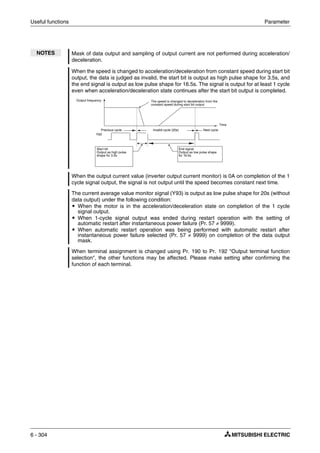
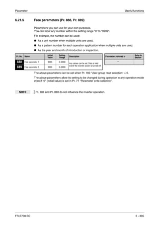
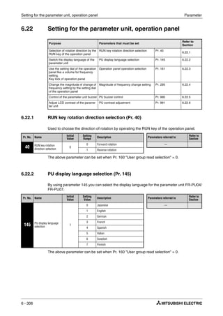
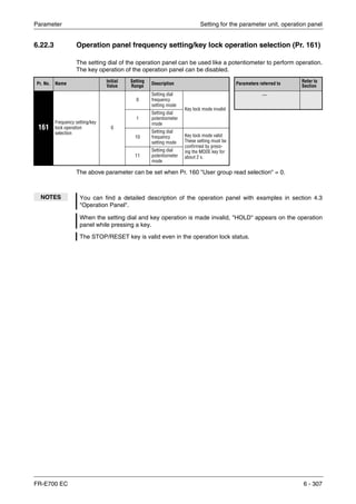
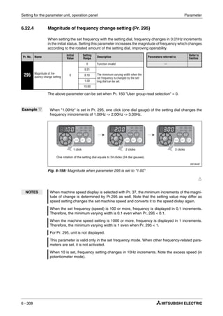
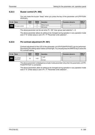

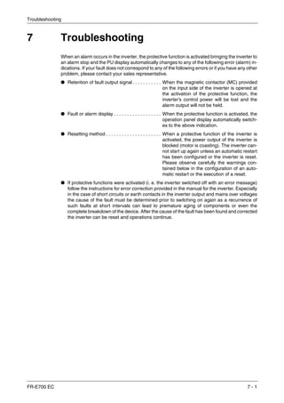
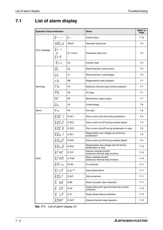
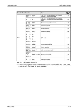
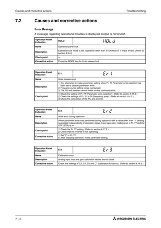
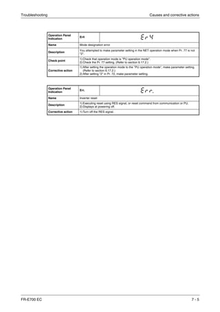
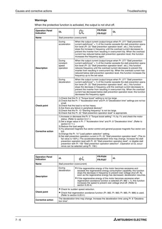
![Troubleshooting Causes and corrective actions
FR-E700 EC 7 - 7
Operation Panel
Indication
PS
FR-PU04
FR-PU07
PS
Name PU Stop
Description
Stop with the STOP/RESET key of the PU is set in Pr. 75 "Reset selection/disconnected
PU detection/PU stop selection". (For Pr. 75, refer to section 6.17.1.)
Check point Check for a stop made by pressing the STOP/RESET key of the operation panel.
Corrective action Turn the start signal off and release with PU/EXT key.
Operation Panel
Indication
RB
FR-PU04
FR-PU07
RB
Name Regenerative brake prealarm
Description
Appears if the regenerative brake duty reaches or exceeds 85% of the Pr. 70 "Special
regenerative brake duty" value. When the setting of Pr. 70 "Special regenerative brake
duty" is the initial value (Pr. 70 = 0), this warning does not occur.
If the regenerative brake duty reaches 100%, a regenerative overvoltage (E. OV२) occurs.
The RBP signal can be simultaneously output with the [RB] display. For the terminal used
for the RBP signal output, assign the function by setting "7 (positive logic) or 107 (negative
logic)" in any of Pr. 190 to Pr. 192 "Output terminal function selection". (Refer to
section 6.10.5.)
Check point
ț Check that the brake resistor duty is not high.
ț Check that the Pr. 30 "Regenerative function selection" and Pr. 70 "Special regenerative
brake duty" values are correct.
Corrective action
ț Increase the deceleration time (Pr. 8).
ț Check the Pr. 30 "Regenerative function selection" and Pr. 70 "Special regenerative
brake duty" values.
Operation Panel
Indication
TH
FR-PU04
FR-PU07
TH
Name Electronic thermal relay function prealarm
Description
Appears if the cumulative value of the Pr. 9 "Electronic thermal O/L relay" reaches or
exceeds 85% of the preset level. If it reaches 100% of the Pr. 9 "Electronic thermal O/L
relay" setting, a motor overload trip (E. THM) occurs. The THP signal can be simultane-
ously output with the [TH] display. For the terminal used for THP signal output, assign the
function by setting "8 (positive logic) or 108 (negative logic)" in any of Pr. 190 to Pr. 192
"Output terminal function selection"). (Refer to section 6.10.5.)
Check point
1)Check for large load or sudden acceleration.
2) Is the Pr. 9 "Electronic thermal O/L relay" setting is appropriate? (Refer to section 6.8.1.)
Corrective action
1) Reduce the load weight or the number of operation times.
2) Set an appropriate value in Pr. 9 "Electronic thermal O/L relay". (Refer to section 6.8.1.)
Operation Panel
Indication
MT
FR-PU04
FR-PU07
—
Name Maintenance signal output
Description
Indicates that the cumulative energization time of the inverter has reached a given time.
When the setting of Pr. 504 "Maintenance timer alarm output" set time is the initial value
(Pr. 504 = 9999), this warning does not occur.
Check point
The Pr. 503 "Maintenance timer" setting is larger than the Pr. 504 "Maintenance timer
alarm output set time" setting. (Refer to section 6.21.3.)
Corrective action Setting "0" in Pr. 503 "Maintenance timer" erases the signal.](https://image.slidesharecdn.com/fr-e700-140613033232-phpapp01/85/Fr-e700-457-320.jpg)
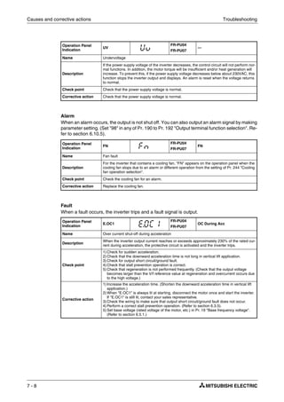
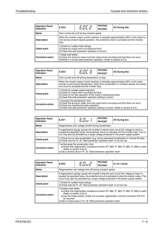
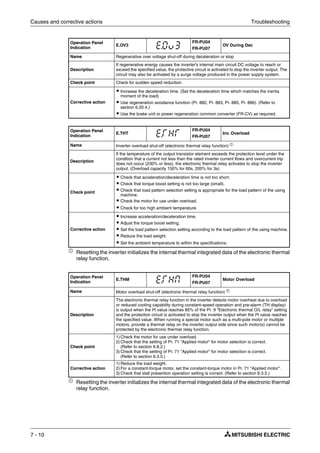
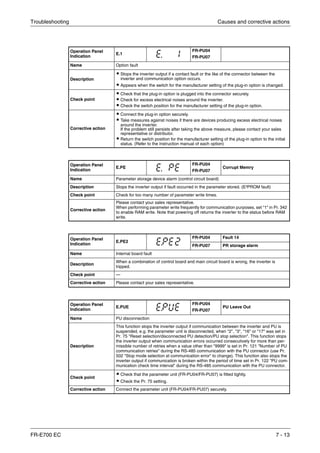
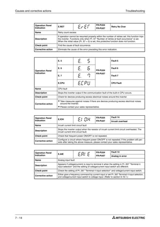
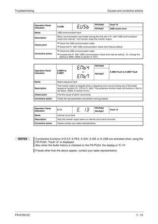
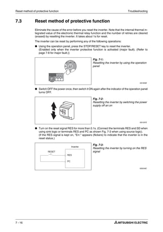
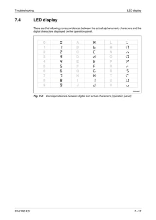
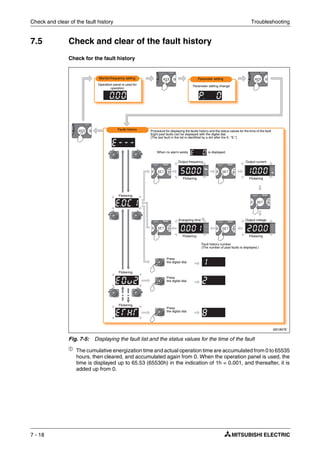
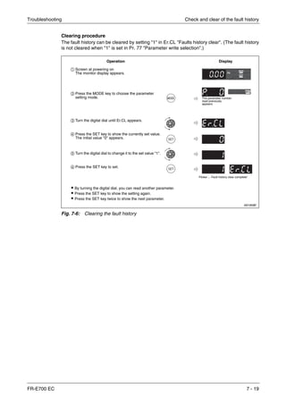
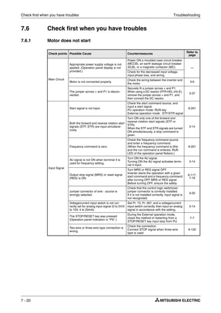
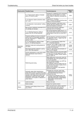
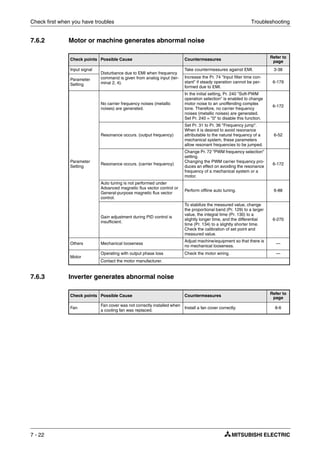
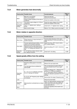
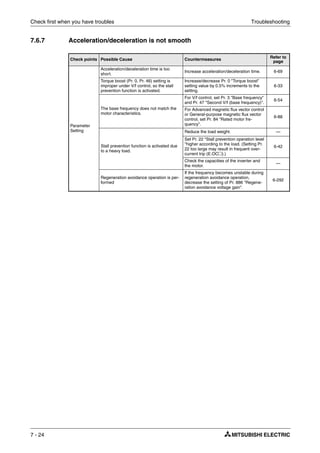
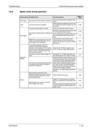
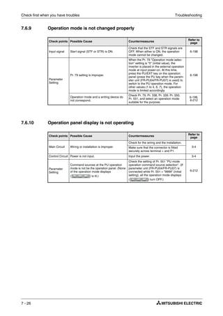
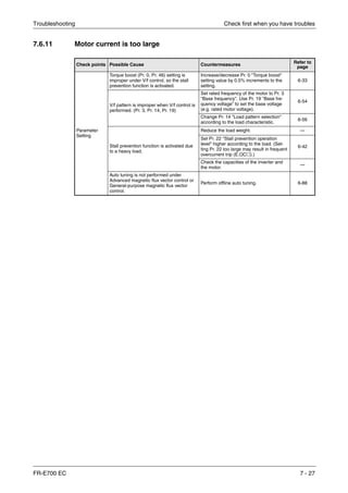
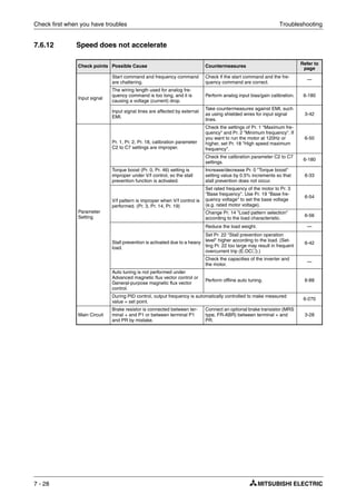
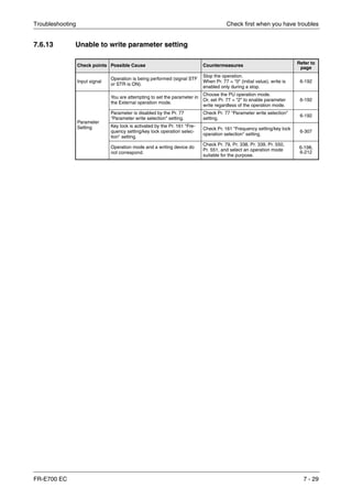
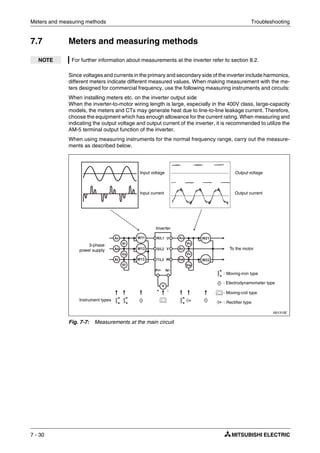
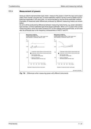
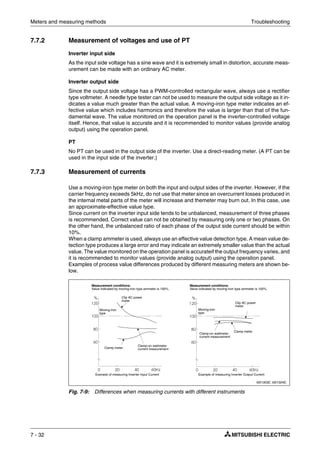
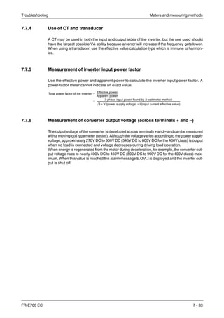

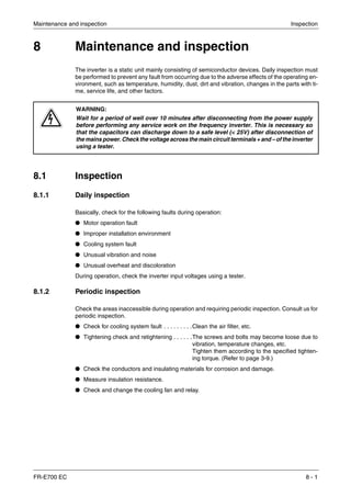
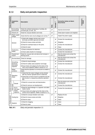
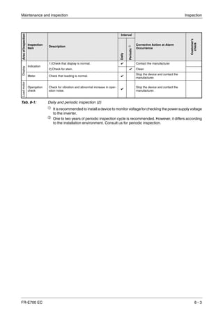
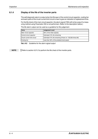
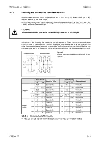
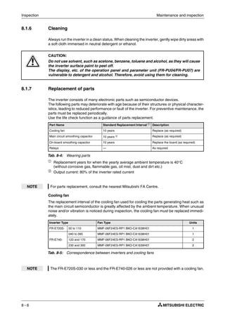
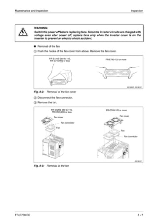
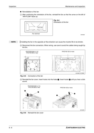
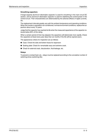
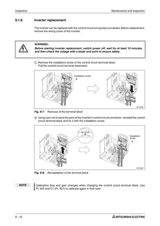
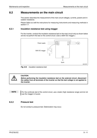
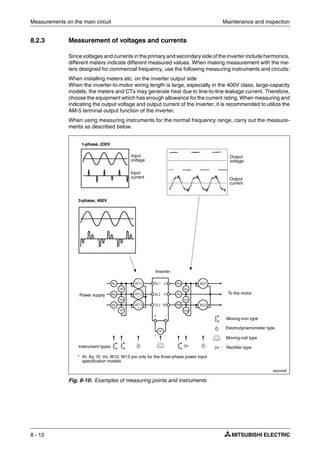
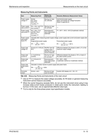
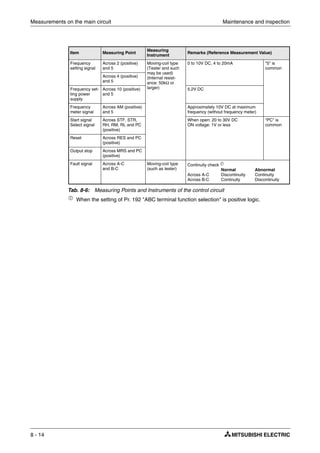
![Appendix Specifications
FR-E700 EC A - 1
A Appendix
A.1 Specifications
A.1.1 1-phase, 200V class
ቢ
The applied motor capacity indicated is the maximum capacity applicable for use of the
Mitsubishi 4-pole standard motor.
ባ The rated output capacity indicated assumes that the output voltage is 230V.
ቤ
Setting 2kHz or more in Pr. 72 "PWM frequency selection" to perform low acoustic noise
operation with the ambient temperature exceeding 40°C, the rated output current is the value
in parentheses.
ብ
The % value of the overload current rating indicated is the ratio of the overload current to
the inverter’s rated output current. For repeated duty, allow time for the inverter and motor
to return to or below the temperatures under 100% load. If the automatic restart after
instantaneous power failure function (Pr. 57) or power failure stop function (Pr. 261) is set
and power supply voltage is low while load becomes bigger, the bus voltage decreases to
power failure detection level and load of 100% or more may not be available.
ቦ
The maximum output voltage does not exceed the power supply voltage. The maximum
output voltage can be changed within the setting range. However, the pulse voltage value
of the inverter output side voltage remains unchanged at about that of the power supply.
ቧ The power supply capacity varies with the value of the power supply side inverter impedance
(including those of the input reactor and cables).
Model FR-E720S-२२२-EC 008 015 030 050 080 110
Rated motor capacity [kW] ቢ 0.1 0.2 0.4 0.75 1.5 2.2
Output
Output capacity [kVA] ባ 0.3 0.6 1.2 2.0 3.2 4.4
Rated current [A] ቤ 0.8
(0.8)
1.5
(1.4)
3.0
(2.5)
5.0
(4.1)
8.0
(7.0)
11.0
(10.0)
Overload current rating ብ 200% of rated motor capacity for 3s; 150% for 60s
Voltage ቦ 3-phase AC, 0V to power supply voltage
Powersupply
Power supply voltage 1-phase, 200–240V AC, -15%/+10%
Voltage range 170–264V AC at 50/60 Hz
Power supply frequency 50/60Hz ± 5%
Rated input capacity [kVA] ቧ 0.5 0.9 1.5 2.5 4.0 5.2
Protective structure IP20
Cooling system Self cooling Forced air cooling
Weight [kg] 0.6 0.6 0.9 1.4 1.5 2.0
Tab. A-1: Specifications
2](https://image.slidesharecdn.com/fr-e700-140613033232-phpapp01/85/Fr-e700-499-320.jpg)
![Specifications Appendix
A - 2
A.1.2 3-phase, 400V class
ቢ
The applied motor capacity indicated is the maximum capacity applicable for use of the
Mitsubishi 4-pole standard motor.
ባ
The rated output capacity indicated assumes that the output voltage is 440V.
ቤ
Setting 2kHz or more in Pr. 72 "PWM frequency selection" to perform low acoustic noise
operation with the ambient temperature exceeding 40°C, the rated output current is the value
in parentheses.
ብ
The % value of the overload current rating indicated is the ratio of the overload current to
the inverter’s rated output current. For repeated duty, allow time for the inverter and motor
to return to or below the temperatures under 100% load.
ቦ
The maximum output voltage does not exceed the power supply voltage. The maximum
output voltage can be changed within the setting range. However, the pulse voltage value
of the inverter output side voltage remains unchanged at about that of the power supply.
ቧ
The power supply capacity varies with the value of the power supply side inverter impedance
(including those of the input reactor and cables).
Model FR-E740-२२२-EC 016 026 040 060 095 120 170 230 300
Rated motor capacity [kW] ቢ 0.4 0.75 1.5 2.2 3.7 5.5 7.5 11 15
Output
Output capacity [kVA] ባ 1.2 2.0 3.0 4.6 7.2 9.1 13.0 17.5 23.0
Rated current [A] ቤ 1.6
(1.4)
2.6
(2.2)
4.0
(3.8)
6.0
(5.4)
9.5
(8.7)
12 17 23 30
Overload current rating ብ 200% of rated motor capacity for 3 s; 150% for 60 s
Voltage ቦ 3-phase AC, 0V to power supply voltage
Powersupply
Power supply voltage 3-phase, 380–480V AC, −15%/+10%
Voltage range 325–528V AC at 50/60Hz
Power supply frequency 50/60 Hz ± 5%
Rated input capacity [kVA] ቧ 1.5 2.5 4.5 5.5 9.5 12 17 20 28
Protective structure IP20
Cooling system Self cooling Forced air cooling
Weight [kg] 1.4 1.4 1.9 1.9 1.9 3.2 3.2 5.9 5.9
Tab. A-2: Specifications
2](https://image.slidesharecdn.com/fr-e700-140613033232-phpapp01/85/Fr-e700-500-320.jpg)
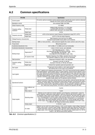
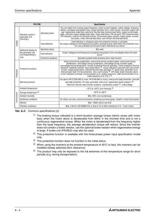
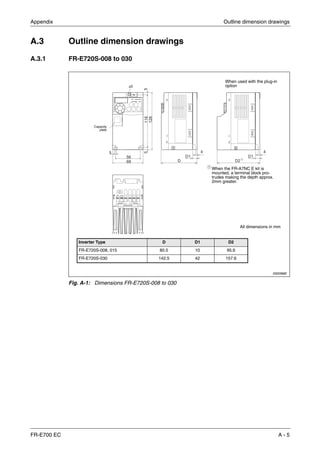
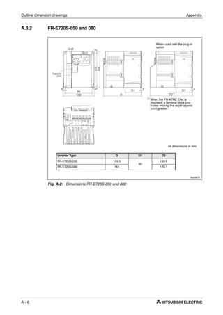
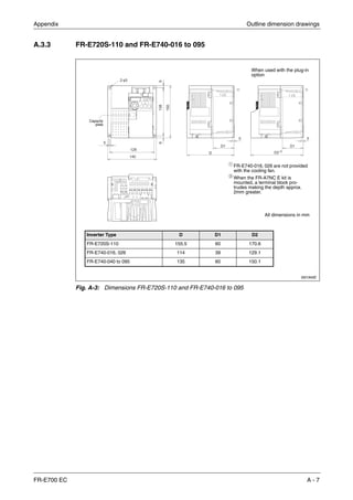
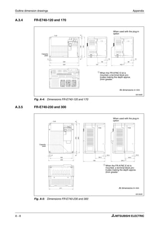
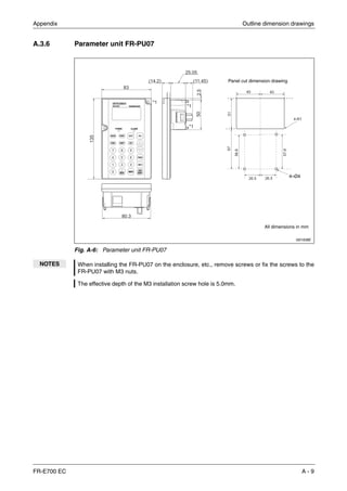
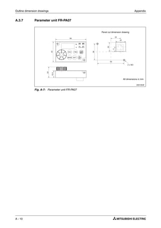
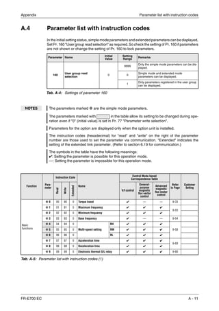
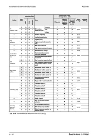
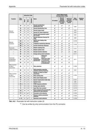
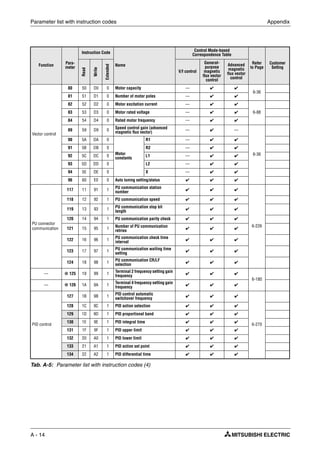
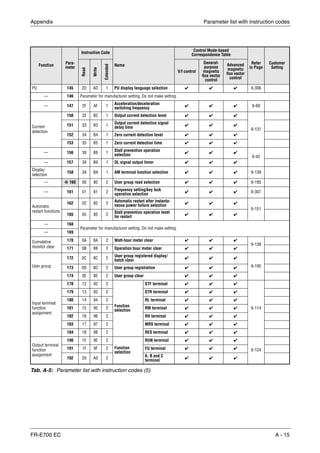
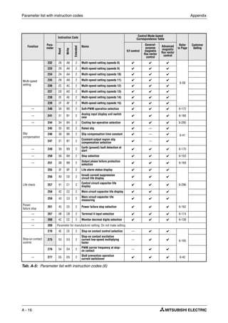
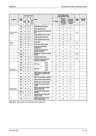
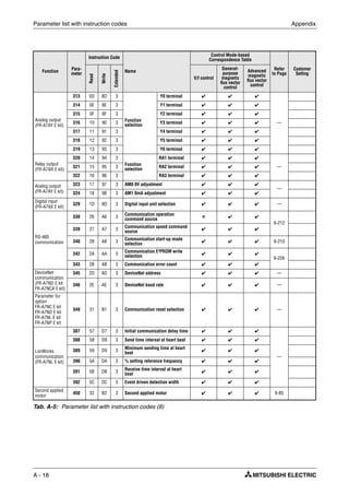
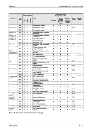
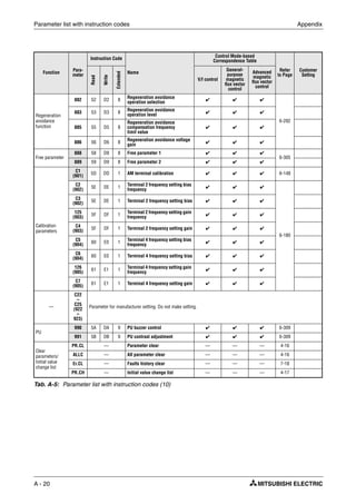
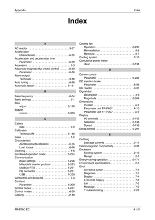


The document provides instructions for the FR-E700 series of frequency inverters from Mitsubishi Electric. It contains safety warnings and instructions for installation, wiring, operation and maintenance of the inverters. The document outlines how to properly handle the inverters to prevent electric shocks and ensure safe use. It also provides technical specifications and connection diagrams to illustrate how to install peripheral devices and integrate the inverters into electrical systems.


![Ct2000 es manual_english_version_1[1].0](https://cdn.slidesharecdn.com/ss_thumbnails/ct2000esmanualenglishversion11-140613213448-phpapp01-thumbnail.jpg?width=640&height=640&fit=bounds)


![Ct2000 pro plus_manual_english[1]](https://cdn.slidesharecdn.com/ss_thumbnails/ct2000proplusmanualenglish1-140613213527-phpapp02-thumbnail.jpg?width=640&height=640&fit=bounds)


