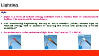
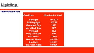
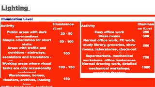
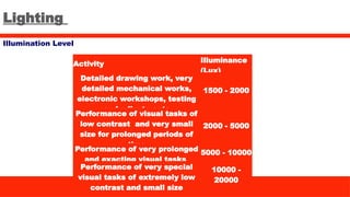
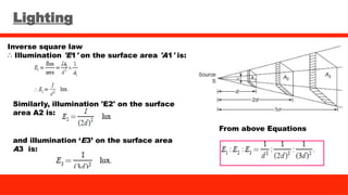
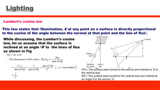
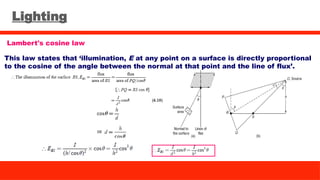
Utilization of Electrical Energy
SUBJECT CODE: EE417
Department of Electrical and Electronics Engineering
National Institute of Technology Puducherry, Karaikal-
609 609
Syllabus
Unit 1: Illumination -lighting calculations - Design of lighting schemes - factory
lighting - flood lighting - electric lamps.
Unit 2: Electric Heating-Electric furnaces and welding - Resistance, inductance and
Arc Furnaces -Construction and fields of application – Induction heating.
Unit 3: Electric drives and control - Group drive - Individual drive - selection of motors
- starting characteristics - Running characteristics.
Unit 4: Traction system – tractive effort calculations - electric braking - recent trend
in electric traction.
Unit 5: Refrigeration and Air-Conditioning -Various types of air conditioning system,
domestic refrigerator and wiring system.
Syllabus
Reference Books
1. Uppal, S.L., 'Electrical Power', Khanna publishers, New Delhi, 1992.
2. Gupta, J.B., 'Utilisation of Electrical Energy and Electric Traction', S.K.Kataria and
sons, 1990.
3. Partab, . H., 'Art and Science of Utilisation of Electrical Energy', Dhanpat Rai and
Sons, New Delhi, 1998.
SECTION BREAK
Insert the title of your subtitle Here
Insert Your Image
Unit 1
Lighting
Light
 Light is a form of radiant energy radiated from a various form of incandescent
bodies. It is expressed in lumen-hours.
 The Illuminating Engineering Society of North America (IESNA) defines light as
“radiant energy that is capable of exciting the retina and producing a visual
sensation.”
 Incandescence is the emission of light from "hot" matter (T 800 K).
≳
Lighting
Light
 Light can be of different colours, which depend on the wave length of the radiation
causing it.
Lighting
Sensitivity of eye
 The eye has greatest sensitivity for wavelengths of about 550 nm
Lighting
Luminous flux
 It is defined as the total quantity of light energy emitted per second from a
luminous body.
 It is represented by symbol F and is measured in lumens.
 The concept of luminous flux helps us to specify the output and efficiency of a
given light source.
Lighting
Luminous Intensity
 Luminous intensity in any particular direction is the luminous flux emitted by the
source per unit solid angle in that direction.
 It is denoted by I and its unit is candela or candle power (CP).
 Luminous intensity of source in a particular direction,
I = φ or F / ω
Lighting
Lumen
 The lumen is the unit of luminous flux and is defined as the luminous flux emitted
per second in one unit of solid angle by a source having an intensity of one candle
power in all direction.
 Lumens = candle power × solid angle = cp × 𝜔
Candle power
 The light radiating capacity of a source is called its candle power.
 The number of lumens given out by a source per unit solid angle in a given
direction is called its candle power.
 It is denoted by CP
Lighting
Illumination
 When light falls on a surface, it becomes visible, the phenomenon is called as
illumination.
 It is defined as luminous flux falling on a surface per unit area.
 It is denoted by E and measured in lumen per square meter or meter- candle.
 E = Ф / A lux
Lighting
Requirement of Good Lighting Scheme
 Illumination Level
 Glare
 Shadows
 Color Rendering
 Lamp Fittings
 Maintenance
Lighting
Illumination Level
 Illumination level is the amount of light measured in a plane surface.
 Illumination level depends on size of the object and its distance from the observer.
 If the object is moving one, then the greater level of illumination is necessary than
the stationary object.
Lighting
Illumination Level
Condition Illumination (lux)
Sunlight 107527
Full Daylight 10752
Overcast Day 1075
Very Dark Day 107
Twilight 10.8
Deep Twilight 1.08
Full Moon 0.108
Quarter Moon 0.0108
Starlight 0.0011
Overcast Night 0.0001
Lighting
Illumination Level
Activity Illuminance
(Lux)
Public areas with dark
surroundings
20 - 50
Simple orientation for short
visits
50 - 100
Areas with traffic and
corridors - stairways,
escalators and travelators -
lifts - storage spaces
100
Working areas where visual
tasks are only occasionally
performed
100 - 150
Warehouses, homes,
theaters, archives, loading
bays
150
Activity Illuminan
ce (Lux)
Easy office work 250
Class rooms 300
Normal office work, PC work,
study library, groceries, show
rooms, laboratories, check-out
areas, kitchens, auditoriums
500
Supermarkets, mechanical
workshops, office landscapes
750
Normal drawing work, detailed
mechanical workshops,
operation theaters
1000
Lighting
Illumination Level
Activity Illuminance
(Lux)
Detailed drawing work, very
detailed mechanical works,
electronic workshops, testing
and adjustments
1500 - 2000
Performance of visual tasks of
low contrast and very small
size for prolonged periods of
time
2000 - 5000
Performance of very prolonged
and exacting visual tasks
5000 - 10000
Performance of very special
visual tasks of extremely low
contrast and small size
10000 -
20000
Lighting
Glare
 Glare is a visual sensation caused by excessive and uncontrolled brightness.
 Glare causes unnecessary eye fatigue.
 It can be prevented by using diffusing glass screens, suitable reflectors and proper
mounting heights.
Lighting
Shadows
 Shadow is a dark area or shape produced by a body coming between rays of light
and a surface.
 The formation of long and hard shadows must be avoided. The hard and long
shadows often cause accidents. Such long shadows can be avoided by :
Using proper mounting heights of lamp.
Using more number of lamps and providing indirect lighting
Employing wide surface source of light
Lighting
Color Rendering
 Color rendering describes how well the light renders colors in objects.
 Color Rendering Index (CRI) measures the ability of a light source to reveal colors
of objects in contrast to a natural light source.
 CRI is a scale from 0 to 100 percent.
Lighting
Lamp Fittings
 A lamp fitting is an electronic device of a luminaire that holds the lamps, serves as
a protective enclosure, or housing, delivers electric power to the lamps, and
incorporates devices for control of emitted light.
Lighting
Maintanence
 A large part of reducing energy use is proper lighting maintenance.
Cleaning dust off fixtures, lamps, and lenses every 6 to 24 months.
Replace lenses if they appear yellow.
Clean or repaint small rooms every year and larger rooms every 2-3 years
because the dirt collected on these surfaces could reduce the amount of light
they reflect.
Consider group light replacement.
Lighting
Plane angle
 An angle formed by two
intersecting straight lines.
 Angle is measured in 2 dimension.
 Plane angle is measured in radian.
 Plane angle,
Solid angle
 An angle formed by two intersecting
planes.
 Angle is measured in 3 dimension.
 Solid angle is measured in steradian.
 Solid angle, dA
dA / r2
Lighting
Utilization factor
 Utilization factor =Lumens received on the working plane/Lumens emitted by the
lamp
 Utilization factor depends on the type of light, light fitting, Colour surface of walls
and ceiling, mounting height of lamps and area to be illuminated.
 Its value lies between 0.4 and 0.6 for direct fittings it varies from 0.1 to 0.35 for
indirect fittings.
Depreciation or Maintenance factor
 D.F = Illumination under normal working conditions / Illumination when everything
is clean.
 Good = 0.70, Medium = 0.65 and Poor = 0.55
Lighting
Waste light factor
 When a surface is illuminated by a number of lamps, there is certain amount of
wastage due to overlapping of light waves.
 Waste light factor =Total lumens emitted by source / Total lumens available after
waste of light.
 Its value will be between 1.2 to 1.5.
Reflection factor
 Reflection factor = Luminous flux leaving the surface / Luminous flux incident.
 It’s value will be always less than 1.
Lighting
Absorption factor
 Absorption factor=Net lumens available on the working plane after absorption /
Total lumens emitted by the lamp.
 When the atmosphere is full of snow or smoke fumes, it absorbs some light.
 It’s value varies from 0.5 to 1.
Luminous efficiency or specific out put
 Luminous efficiency = Number of lumens emitted / Electric power consumed by the
source.
 It’s unit is lumen/watt (lm/W).
Lighting
Spacing to mounting height ratio (SHR)
 Spacing between luminaires divided by their height above the horizontal reference
plane.
Room index
 L is the length of the room, W is its width and H is the mounting height above the
work plane.
Lighting
Mean horizontal candle power (MHCP)
 MHCP is defined as the mean of the candle power of source in all directions
in horizontal plane.
Mean spherical candle power (MSCP)
 MSCP is defined as the mean of the candle power of source in all directions
in all planes.
Mean hemispherical candle power (MHSCP)
 MHSCP is defined as the mean of the candle power of source in all directions
above or below the horizontal plane.
Lighting
Reduction factor
Reduction factor of the source of light is defined as the ratio of its mean
spherical candle power to its mean horizontal candle power.
DRILL PROBLEMS
A 200-V lamp takes a current of 1.2 A, it produces a total flux of 2,860
lumens. Calculate:
a) the MSCP of the lamp and
b) the efficiency of the lamp.
Solution:
DRILL PROBLEMS
A room with an area of 6 × 9 m is illustrated by ten 80-W lamps. The luminous
efficiency of the lamp is 80 lumens/W and the coefficient of utilization is 0.65.
Find the average illumination.
Solution:
DRILL PROBLEMS
The flux emitted by 100-W lamp is 1,400 lumens placed in a frosted globe of 40 cm
diameter and gives uniform brightness of 250 milli-lumens/m2
in all directions.
Calculate the candle power of the globe and the percentage of light absorbed by the
globe.
Solution:
Flux emitted by the globe = brightness × globe area
= 1,256.63 lumens
Flux absorbed by the globe = flux emitted by source – flux emitted by globe
= 1,400 – 1,256.63 = 143.36 lumens.
Lighting
LAWS OF ILLUMINATION
Mainly there are two laws of illumination.
 Inverse square law.
 Lambert's cosine law.
Inverse square law
This law states that ‘the illumination of a surface is inversely proportional
to the square of distance between the surface and a point source’.
Lighting
Inverse square law
Proof
Let, ‘S’ be a point source of luminous intensity
‘I’ candela, the luminous flux emitting from
source crossing the three parallel plates
having areas A1 A2, and A3 square meters,
which are separated by a distances of d, 2d,
and 3d from the point source respectively as
shown in Fig.
Luminous flux reaching the area A1
= luminous intensity × solid angle
Lighting
Inverse square law
∴ Illumination 'E1' on the surface area 'A1' is:
Similarly, illumination 'E2' on the surface
area A2 is:
and illumination ‘E3’ on the surface area
A3 is:
From above Equations
Lighting
Lambert's cosine law
This law states that ‘illumination, E at any point on a surface is directly proportional
to the cosine of the angle between the normal at that point and the line of flux’.
While discussing, the Lambert's cosine
law, let us assume that the surface is
inclined at an angle ‘θ’ to the lines of flux
as shown in Fig
PQ = The surface area normal to the source and inclined at ‘θ’ to
the vertical axis.
RS = The surface area normal to the vertical axis and inclined at
an angle θ to the source ‘O’.
Lighting
Lambert's cosine law
This law states that ‘illumination, E at any point on a surface is directly proportional
to the cosine of the angle between the normal at that point and the line of flux’.
Lighting
Calculation of number of light points for interior illumination
 The number of lamps required in a particular place can be designed by following
three methods
Watt per square meter:
 This is a rough method. Watts per square meter are calculated on the basis of
efficiency of lamp (lm/watt).
Inverse square law:
 This method is used in street light calculations. In this method law of illumination
is used. For this candle power of the lamps should be known.
Lumen per square meter method:
 This method is used for design of general lighting. In this method, lamp efficiency,
Depreciation factor, utilization factor etc. are used.
Lighting
Lumen method steps
1. Find required lux level
2. Select luminaire
3. Determine room index
4. Determine Number of Fixtures
N =number of lamps required, E=illumination level required (lux), A = area at
working plane height (m2
), F = average luminous flux from each lamp (lm),
UF=Utilization factor and MF=Maintenance factor
Lighting
Lumen method steps
5. Determine Minimum spacing between luminaire
 Minimum spacing = SHR * H
H= Mounting height
SHR= Space to height ratio.
6. Determine Number of required rows of luminaire along width of the room
 Number of required rows= Width of the room/ Minimum spacing
7. Determine Number of luminaire in each row
 Number of luminaire in each row= Total luminaire / Number of rows
Lighting
Lumen method steps
8. Axial spacing along luminaire
 Axial spacing= Length of the room/ Number of luminaire in each row
9. Transverse spacing between luminaire
 Transverse spacing = Width of the room/ Number of luminaire in each row
Lighting
Flood Lighting
 Flood light means flooding of large surfaces with light from powerful projectors.
 Aesthetic Flood Lighting- For increasing the beauty of ancient buildings and
monuments during night
Lighting
Flood Lighting
 Industrial and commercial flood lighting- Illumination of airports, dockyards,
railway yards, sports stadiums and so on.
Lighting
Flood Lighting
 Industrial and commercial flood lighting
Lighting
Flood Lighting
 Advertising
Lighting
Flood Lighting
Projectors
 In order to have a good flood lighting, it is necessary to direct the light from a lamp
into a beam. The reflector and the housing used with the lamp is called flood light
projector.
 It should be robust and weather proof.
 To have the maximum amount of light falling on an object, the projector is provided
with silvered glass, stainless steel or chromium plate surface for the projector.
Narrow beam projectors
 Beam spread between 120
to 250
.
 Used for distance beyond 70 m.
Lighting
Flood Lighting
Projectors
Medium angle projectors
 Beam spread between 250
to 400
.
 Used for distance between 30 to 70 m.
Wide angle projectors
 Beam spread between 400
to 900
.
 Used for distance below 30 m.
Lighting
Factory / Industrial Lighting
A good industrial lighting should take into account
 Adequate quantity of illumination
 Good quality of illumination.
Adequate quantity of illumination
 A general lighting system should be designed to provide a uniform
distribution of light over the entire work area. Where work areas are close
to walls, such as work benches, the first row of luminaires should be located
closer to wall or additional lighting should be provided over the particular
work space.
Lighting
Factory Lighting
Adequate quantity of illumination
 To ensure that a given illumination level will be maintained, it is
necessary to design a system to give initially more light than the required
minimum.
 In locations where dirt will collect very rapidly on luminaire surfaces
and where adequate maintenance is not available, the initial value should be
still higher.
 Higher initial values shall be provided for the absorption of the
light while designing lighting requirements.
Lighting
Factory Lighting
Good quality of illumination
 Quality of illumination pertains to the distribution of brightness in the visual
environment.
 Brightness should contribute favorably to visual performance, visual comfort, ease
of seeing, safety and aesthetics for the specific visual task involved.
 Factors which has effect on visibility and the ability to see easily, accurately and
quickly.
Direct Glare
Lighting
Factory Lighting
Good quality of illumination
Luminance and Luminance Ratios
 The ability to see detail depends upon the contrast between the detail
and its background. The greater the contrast, difference in luminance,
the more readily the seeing task is performed.
Reflected Glare
Lighting
Factory Lighting
Good quality of illumination
Distribution, Diffusion and Shadows
 The general lighting system for a factory should be designed for
uniformly distributed illumination.
 Diffuse reflection is the reflection of light from a surface such that an
incident ray is reflected at many angles, rather than at just one angle as
in the case of specular reflection. The visibility of objects, excluding
light-emitting ones, is primarily caused by diffuse reflection of light.
Colour quality of light
 The light source should have the good colour rendering index.
Lighting
Factory Lighting
Selection of light for industries
 For industrial lighting the sources of light generally available at present are
tungsten filament lamps, tubular fluorescent lamps, high pressure mercury vapour
(HPMV) discharge lamps and LEDs.
 The selection of any one of these or a combination of these depends on
• Type of application
• Atmospheric conditions of
industrial interiors and/or
exteriors
• Structural features
• Initial outlay
• Running cost
• Ease of maintenance
Lighting EXAMPLE PROBLEMS
The Illumination at a point on a working plane directly below the lamp is to be 80
lumens/m2
. The lamp gives 180 C.P. uniformly below the horizontal plane. Determine:
(i) The height at which the light is suspended.
(ii) The illumination at a point on the working plane 1.5 m away from the vertical axis
of the lamp.
Lighting EXAMPLE PROBLEMS
Lighting
Types of lamps
 Thermal light sources (Thermal radiation)
Incandescent lamps
Halogen lamps
 Discharge lamps (Gas discharge)
Low-intensity discharge lamps
Fluorescent lamp
Compact fluorescent lamp
High-intensity discharge lamps
Metal halide lamp
Sodium discharge lamp
Mercury discharge lamp
Lighting
Types of lamps
 Semiconductor light sources (Electroluminescence)
Light Emitting Diode (LED) lamp
Organic Light Emitting Diode (OLED) lamp
Lighting
Types of lamps
Incandescent lamps
Features
Tungsten filament yields light
Electric wire delivers power
Glass bulb protects filament
Inert gas fill prolongs life
Working
 When current is passed through the wire, both heat and light are produced.
Lighting
Types of lamps
Incandescent lamps
Working
 When wire is red hot it emits more heat as compared to light.
 At white hot position, the amount of light radiation being much more than heat
energy.
 Material used for filament is tungsten, carbon, osmium or tantalum.
 Glass blub is filled with a chemical inert gas as nitrogen or argon.
Lighting
Types of lamps
Incandescent lamps
Working
 Lamps below 40watts are not filled with gas to avoid waste of heat.
 Type and color used for the glass cover produce a vital effect on the quality of light
emitted.
 Efficiency of coiled lamp is high as compared to single coil lamps.
 If operating voltage increases, the life of the lamp reduces.
Lighting
Types of lamps
Halogen lamps
 Features
Service life and luminous efficiency
better than incandescent lamps
Dimmable
Brilliant light
Excellent colour rendering
Lighting
Types of lamps
Halogen lamps
Working
 In a typical incandescent lamp, tungsten slowly evaporates from the burning
filament. This causes blackening of the lamp, which decreases light output and
reduces life.
 Halogen lamps are largely able to eliminate this problem because the halogen gas
reacts chemically with the evaporated tungsten to prevent it from affixing to the
glass.
 The halogen light bulb or lamp is a type of incandescent lamp which uses a halogen
gas in order to increase both light output and rated life.
 Current flows through a filament and heats it up in exactly the same way as in an
incandescent lamp.
Lighting
Types of lamps
Fluorescent lamp
 Features
High to very high luminous efficiency
Very good colour rendering
Long service life
Dimmable
Lighting
Types of lamps
Fluorescent lamp
Working
 An alternating electrical field between two electrodes in the discharge tube
produces invisible UV radiation.
 The tube’s white fluorescent coating converts this radiation into high-quality,
visible light.
 These lamps need ignitors and current limiting; these functions are combined in an
electronic ballast.
Lighting
Types of lamps
Compact fluorescent lamp
 Features
Compact designs
High luminous efficiency
Excellent colour rendering
Dimmable
Lighting
Types of lamps
Compact fluorescent lamp
Working
 An alternating electrical field between two electrodes in the discharge tube
produces invisible UV radiation.
 The tube’s white fluorescent coating converts this radiation into high-quality,
visible light.
 These lamps need ignitors and current limiting; these functions are combined in an
electronic ballast.
Lighting
Types of lamps
Home work:
Metal halide lamp
Sodium discharge lamp
Mercury discharge lamp
LED and OLED
SECTION BREAK
Insert the title of your subtitle Here
Insert Your Image
Unit 2
Electric Heating
Introduction
 Electric heating is a process in which the electrical energy is converted into heat
energy.
 When current is passed through a conductor, the conductor becomes hot
(resistance heating)
 When a magnetic material is brought in the vicinity of an alternating magnetic
field, heat is produced in the magnetic material (induction heating).
 When an electrically insulating material was subjected to electrical stresses, heat
is produced in the material (dielectric heating).
Electric Heating
Introduction
 Domestic applications
room heaters
immersion heaters for water heating
hot plates for cooking
Electric kettles
electric irons
pop-corn plants
electric ovens for bakeries
electric toasters
melting of metals
heat treatment of metals like
annealing, tempering, soldering and
brazing etc.
moulding of glass
baking of insulators
enameling of copper wires
 Industrial applications
Electric Heating
Advantages of electric heating
 Cleanliness
 Absence of flue gases
 Ease of control
 Low maintenance requirement
 Special heating requirement
 Higher efficiency
Electric Heating
Different Methods of Heat Transfer
Conduction
 In this mode of heat transfer, one molecule of the body gets heated and transfers
some of the heat to the adjacent molecule and so on.
 There is a temperature gradient between the two ends of the body being heated.
Convection
 Convection is the transfer of heat by the movement of a fluid (liquid or gas) between
areas of different temperature.
Radiation
 Heat transfer due to emission of electromagnetic waves is known as thermal
radiation
Electric Heating
Classification of electric heating methods
Power frequency heating
 Resistance heating
Direct resistance heating
Indirect resistance heating
 Arc heating
Direct arc heating
Indirect arc heating
High frequency heating
 Induction heating
Direct core type induction heating
Coreless type induction heating
 Dielectric heating
 Infrared heating
Electric Heating
Resistance Heating
Requirements of a good heating material
 High specific resistance
 High melting point
 Free from oxidation
 Low temperature coefficient
 Some commercial materials-Ni-Cr, Ni-Cr-Fe, Ni-Cu and Fe-Cr-Al
Electric Heating
Resistance Heating
Direct Resistance Heating
 In this method the material (or charge) to be heated is
treated as a resistance and current is passed through it.
 Two electrodes are inserted in the material or charge to
be heated. Electrodes can be connected to either a.c. or
d.c. supply.
 The material or charge may be in the form of powder,
small solid pieces or liquid.
 Two electrodes will be required in the case of d.c. or
single-phase a.c. supply but there would be three
electrodes in the case of 3-phase supply.
Electric Heating
Resistance Heating
Direct Resistance Heating
 When the charge is in the form of small pieces, a
powder of high resistivity material is sprinkled over the
surface of the charge to avoid direct short circuit.
 This method of heating is employed in salt bath
furnace and electrode boiler for heating water.
Electric Heating
Resistance Heating
Indirect Resistance Heating
 In this method of heating, electric current is passed
through a resistance element which is placed in an
electric oven (Heating Chamber).
 The heat so produced is delivered to the charge either by
radiation or convection or by a combination of the two.
 Sometimes, resistance is placed in a cylinder.
 This arrangement provides uniform temperature.
Electric Heating
Arc Heating
 The heating of matter by an electric arc. The matter may be gas, liquid or solid.
 An electric arc is a phenomenon in which an electric current (a flow of electrons)
is caused to flow between two electrodes separated by a gas.
 Direct arc heating-Electric arc is formed between the electrodes and the charge
(Material to be heated).
 Indirect arc heating- Radiation contributes for the heating of material.
 Electrodes used are, Carbo / graphite / self-braking electrodes.
Electric Heating
Arc Heating
Direct Arc Heating
 Since the arc is formed between electrodes and the
charge, heat is produced by flow of current through the
charge which offers very low resistance.
 Three phase supply is generally employed for large
capacity furnaces. These three phase supply is connected
to these electrodes spaced at the corners of an equilateral
triangle; the material forms the star point.
 The arc is controlled by either applying variable voltage or
by adjusting the arc length and the arc resistance.
Electric Heating
Arc Heating
Direct Arc Heating
 The most important feature of the direct arc furnace is
that the stirring action is inherent due to the
electromagnetic force setup by the current. This results in
uniform heating of material.
 The most common application is to produce steel.
Electric Heating
Arc Heating
Indirect Arc Heating
 The arc is struck by short circuiting the electrodes
manually or automatically for a moment and then,
withdrawing them apart. The heat from the arc and the hot
refractory lining is transferred to the top layer of the charge
by radiation.
 The heat from the hot top layer of the charge is further
transferred to other parts of the charge by conduction.
 Since no current passes through the body of the charge,
there is no inherent stirring action due to electro-magnetic
forces set up by the current.
Electric Heating
Arc Heating
Indirect Arc Heating
 Hence, such furnaces have to be rocked (moved)
continuously in order to distribute heat uniformly by
exposing different layers of the charge to the heat of the
arc.
 An electric motor is used to operate suitable grinders and
rollers to impart rocking motion to the furnace.
 Rocking action (Movement) provides not only thorough
mixing of the charge.
Electric Heating
Arc Heating
Indirect Arc Heating
 Since in this furnace, charge is heated by radiation only, its
temperature is lower than that obtainable in a direct arc
furnace.
 Such furnaces are mainly used for melting nonferrous
metals although they can be used in iron foundries where
small quantities of iron are required frequently.
Electric Heating
Induction Heating
 Induction heating is based on the principle of
electromagnetic induction.
 The current flows on the outer surface of metallic
disc.
 The current flow is restricted axially to that
surface of the metal with the turns of the heating
coil.
 The heat energy is transferred to the metal at an
extremely rapid rate, much faster that any
conventional method of heating metal.
Electric Heating
Induction Heating
 The heat is generated within the metal without any
physical contact between the source of electrical
energy.
 If the current continues to flow in the disc, the
surface would attain extremely higher temperature.
 The heat in the disc can be controlled by,
High coil current
Larger number of coil turns
High frequency supply
Closing spacing between the coil and work
Magnetic material disc-High permeabillity
Higher electrical resistivity of the disc
Electric Heating
Induction Heating
Core type induction heating
 The furnace consists of hearth (Base of furnace)
in the form of a trough which contains the
material to be melted in the form an annular
ring.
 This metal ring quite large in diameter is
magnetically inter-linked with an electrical
winding which is energized from an AC source.
 The furnace is therefore a transformer in which
the material to be heated forms a single turn
short circuited secondary and is magnetically
coupled to the primary by an iron core.
Electric Heating
Induction Heating
Core type induction heating
 The magnetic coupling between primary and
secondary is poor. This results in high leakage
current and low PF.
 The melting rapid and clean.
 The inherent stirring action of the melt insures a
uniform temperature in the furnance.
Electric Heating
Induction Heating
Core-less type induction heating
 The furnace consists of a ceramic crucible
(vessel in which metals or other substances are
heated) cylindrical in shape enclosed within a
coil which forms the primary of transformer and
the charge in the crucible, the secondary of
transformer.
 The flux produced by the primary winding sets
up eddy-current in the charge which flow
concentrically with those in the primary winding.
 These current heat up the charge to the melting
point and provide stirring action to the charge.
Electric Heating
Induction Heating
Core-less type induction heating
 The crucible and coil are relatively light in
construction and could be conveniently tilted for
pouring.
 These furnaces are used for steel production.
Electric Heating
Dielectric heating
 It is also called high-frequency capacitive heating
and is used for heating insulators like wood, plastics
and ceramics etc. which cannot be heated easily and
uniformly by other methods.
 This method of heating is based on dielectric loss
and this dielectric loss can be expresses as,
Conducting
Plates
V-applied voltage magnitude
F-Frequency of applied voltage
D-distance between plates
εr-Relative permittivity of the medium
A-Area of the plate
d-Thickness of the material to be heated
Δ-Loss angle
Material to
be heated.
Electric Heating
Dielectric heating
 The supply frequency required for dielectric heating is between 10-50 MHz.
 The applied voltage is upto 20 kV.
 The overall efficiency of dielectric heating is about 50%.
Electric Heating
Dielectric heating
Applications
 For gluing of multilayer plywood boards.
 For baking of sand cores which are used in the moulding process.
 For preheating of plastic compounds before sending them to the moulding section.
 For drying of tobacco after glycerine has been mixed with it.
 For baking of biscuits and cakes etc. in bakeries with the help of automatic
machines.
 For electronic sewing of plastic garments like raincoats etc. with the help of cold
rollers fed with highfrequency supply.
Electric Heating
Dielectric heating
Applications
 For dehydration of food which is then sealed in air-tight containers.
 For removal of moistures from oil emulsions.
 In diathermy for relieving pain in different parts of the human body.
 For quick drying of glue used for book binding purposes.
HW: Infrared heating
Electric Heating
Electric welding
 It is defined as the process of joining two metal pieces, in which the electrical
energy is used to generate heat at the point of welding in order to melt the joint.
 Resistance Welding
Spot Welding
Seam Welding
Projection Welding
Butt Welding
Flash Butt Welding and Percussion Welding
 Arc Welding
Carbon Arc Welding
Shielded Metal Arc Welding
Gas Metal Arc Welding
Submerged Arc Welding
Electric Heating
Electric welding
Resistance Welding
The term ‘resistance welding’ denotes a process in which welding heat is produced
by the resistance offered to the passage of electric current through the two metal
pieces being welded.
Spot Welding
 It consists of two electrodes which are mounted on
two arms.
 The lower arm is fixed whereas the upper one is
movable.
Electric Heating
Electric welding
Spot Welding
 The electrodes are made of low resistance, hard-
copper alloy and are either air cooled or water
cooled.
 Mechanical pressure is applied by the tips of the two
electrodes.
 These electrodes are used not only for providing the
pressure but also to carry the welding current and
concentrate the welding heat on the weld spot
directly below them.
Electric Heating
Electric welding
Spot Welding
 As the movable electrode comes down and presses
the two work pieces together, current is passed
through the assembly.
 The metals under the pressure zone get heated upto
about 950°C and fuse together.
 As they fuse, their resistance is reduced to zero,
hence there is a surge of current. This surge is made
to switch off the welding current automatically.
 Spot welding is used for galvanized, tinned and lead
coated sheets and mild steel sheet work.
Electric Heating
Electric welding
Seam Welding
 Seam welding is the series of continuous spot
welding.
 If number of spots obtained by spot welding are
placed very closely that they can overlap, it gives rise
to seam welding.
 It consists of two wheel type or roller electrodes.
 These electrodes are placed over metal pieces to be
joined.
Electric Heating
Electric welding
Seam Welding
 When these electrodes travel over the metal pieces
which are under pressure, the current passing
through them heats the two metal pieces to the
plastic state and results into continuous spot welds.
 It is usually employed in welding of pressure tanks,
transformers, condensers, evaporators, air craft
tanks, refrigerators, varnish containers and so on.
 The materials which can be welded by this method
are High-carbon steel, stainless steel, Coated steel,
alloys of aluminium, nickel and magnesium.
Electric Heating
Electric welding
Projection Welding
 It consists of two electrodes and are flat metal plates
known as platens.
 The two pieces of metal to be welded are held
together in between the two platens, one is movable
and the other is fixed.
 One of the two metal pieces is run through a machine
that makes the bumps or projections of required
shape and size.
Electric Heating
Electric welding
Projection Welding
 When the current is passed and the electrode
pressure is applies, the projection collapses and the
sheets are welded together.
 Projection welding is used for steel radiator, coupling
elements, brake shoes and so on.
 The materials which can be welded by this method
are low carbon steel, brass, aluminium and copper.
Electric Heating
Electric welding
Butt Welding
 In this case, the two workpieces are brought into
contact end-to-end.
 Then, they are placed in the jaws of the machine
which presses them close together.
 When a suitable pressure is reached, the heavy
current is switched on and the current flowing
through the contact resistance between the ends
brings them to welding heat.
 Butt welding is used for welding of rods, pipes, wires
and so on.
Electric Heating
Electric welding
Butt Welding
 The materials which can be welded by this method
are aluminium alloys, brass, copper nickel alloys,
stainless steel, high-carbon and low-carbon steel and
gold.
Electric Heating
Electric welding
Flash Butt Welding
 In this method of welding, the two pieces to be
welded are brought very nearer to each other under
light mechanical pressure.
 These two pieces are placed in a conducting
movable clamps.
 When high current is passed through the two metal
pieces and they are separated by some distance,
then arc established between them.
 This arc or flashing is allowed till the ends of the
workpieces reach melting temperature.
Electric Heating
Electric welding
Flash Butt Welding
 Then, the supply will be switched off and the pieces
are rapidly brought together under light pressure.
 As the pieces are moved together, the fused metal
and slag come out of the joint making a good solid
joint.
 Flash welding can be used for welding many ferrous
and non-ferrous alloys except for cast iron, lead,
zinc, antimony alloys and bismuth.
Electric Heating
Electric welding
Percussion Welding
 It consists of one fixed holder and the other one is
movable.
 The pieces to be welded are held apart, with the help
of two holders.
 When the movable clamp is released, it moves rapidly
carrying the piece to be welded.
 There is a sudden discharge of electrical energy
which establishes an arc between two surfaces and
heating them to their melting temperature.
Electric Heating
Electric welding
Percussion Welding
 As the pieces come in contact with each other under
heavy pressure, the arc is extinguished due to the
percussion blow of the two parts and the force
between them affects the weld.
 The materials which can be welded by this method
are aluminium alloys, copper alloys, stainless steel
and high-carbon and low-carbon steel.
Electric Heating
Electric Arc Welding
 Electric Arc Welding is the process of joining two
metallic pieces or melting of metal.
 The heat is developed by an arc struck between an
electrode and the metal to be welded or between the
two electrodes.
Carbon Arc Welding
 In this method, the arc is struck between the carbon
electrode and the metal or between two carbon
electrodes.
 In the carbon arc welding, carbon or graphite rods
are used as electrode.
Electric Heating
Electric Arc Welding
Carbon Arc Welding
 The arc produced between electrode and base metal
which heat the metal to the melting temperature.
 The filler metal is required for this welding method.
 If the operation required is fast and / or large amount
of filler material is to be deposited, electrode of 2.5
cm diameter with currents of the order of 500 A to
800 A are employed.
 This method of welding is suitable for non ferrous
metal.
Electric Heating
Electric Arc Welding
Shielded Metal Arc Welding
 This method uses flux coated electrodes.
 They consist of a metal core wire surrounded by a
thick flux coating applied by extrusion, winding or
other processes.
 The heat of the arc is used to bring the work piece
and the electrode to molten state.
HW: Gas Metal Arc Welding and Submerged Arc Welding
SECTION BREAK
Insert the title of your subtitle Here
Insert Your Image
Unit 3
Electric Drives
Introduction
 Motion control is required in large number of industrial and domestic applications
like transportation systems, rolling mills, paper machines, textile mills, machine
tools, fans, pumps, robots, washing machines etc.
 Systems employed for motion control are called drives.
 Drives may employ any of prime movers such as diesel or petrol engines, gas or
steam turbines, steam engines, hydraulic motors and electric motors for supplying
mechanical energy for motion control.
 Drives employing electric motors are known as electrical drives.
 An electric drive can be defined as an electromechanical device for converting
electrical energy into mechanical energy to impart motion to different machines
and mechanisms for various kinds of process control.
Electric Drives
Applications
 Paper mills
 Cement Mills
 Textile mills
 Sugar Mills
 Steel Mills
 Electric Traction Vehicle
 Petrochemical Industries
Electric Drives
Classification of electric drives
According to Mode of Operation
Continuous duty drives
Short time duty drives
Intermittent duty drives
According to Dynamics and Transients
Uncontrolled transient period
Controlled transient period
According to Number of machines
Individual drive
Group drive
Multi-motor drive
According to Means of Control
Manual
Semi automatic
Automatic
Electric Drives
Classification of electric drives
According to Methods of Speed Control
Reversible and non-reversible uncontrolled constant speed.
Reversible and non-reversible step speed control.
Variable position control.
Reversible and non-reversible smooth speed control.
Electric Drives
Classification of electric drives
DC drives
 DC drive comprises of DC motor and load with any speed control mechanism.
AC drives
 AC drive comprises of AC motor and load with any speed control mechanism.
Electric Drives
Classification of electric drives
Individual drive
 In individual drive, a single electric motor is used to drive one individual machine.
Such a drive is very common in most of the industries.
Advantages
 It is more clean and safe.
 Machines can be located at convenient places.
 If there is a fault in one motor, the output and operation of the other motors will
not be effected.
Electric Drives
Classification of electric drives
Individual drive
Advantages
 The continuity in the production of the industry is ensured to a higher degree.
Disadvantages
 Initial cost will be high.
 Power loss is high.
Electric Drives
Classification of electric drives
Group drives
 Electric drive that is used to drive one or more than two machines from line shaft
through belts and pulleys is known as group drive.
 It is also sometimes called the line shaft drive.
 It is simple to replace the engine by means of motor and retaining the rest of
power transmission system when there is a switch over from non-electric drive to
electric drive.
Electric Drives
Classification of electric drives
Group drives
Advantages
 The cost of installation is less. For example, if the power requirement of each
machine is 10 HP and there are five machines in the group, then the cost of five
motors will be more than one 50-HP motor.
 If it is operated at rated load, the efficiency and power factor of large group drive
motor will be high.
Electric Drives
Classification of electric drives
Group drives
Advantages
 The maintenance cost of single large capacity motor is less than number of small
capacity motors.
 It is used for the processes where the stoppage of one operation necessitates the
stoppages of sequence of operations as in case of textile mills.
 It has overload capacity.
Electric Drives
Classification of electric drives
Group drives
Disadvantages
 If there is any fault in the main motor, all the machines connected to the motor will
fail to operate; thereby, paralyzing a part of industry until the fault is removed.
 It is not possible to install any machine at a distant place.
 The possibility of the installation of additional machines in an existing industry is
limited. The level of noise produced at the work site is quite large.
 The speed control of different machines using belts and pulleys is difficult.
Electric Drives
Classification of electric drives
Multi-motor drive
 In multi-motor drives, several separate motors are provided for operating different
parts of the same machine.
 Ex: In traveling cranes, three motors are used for hoisting, long travel, and cross-
travel motions. Multi-motor drive is used in complicated metal cutting machine
tools, rolling mills and so on.
Electric Drives
Nature of the load
 Loads which require constant torque at
all speeds (Curve 1).
 Example
Cranes during hoisting
Hoist winches
Machine tool feed mechanisms
In piston pump which is operating
against the pressure head.
Electric Drives
Nature of the load
 Loads which require increase in torque
directly proportional to the speed (Curve
2).
 Example
Rollers
Smoothing machines
Electric Drives
Nature of the load
 Loads which require increase in torque
with the square of speed (Curve 3).
 Example
Blowers
Fans
Centrifugal pumps
Ship propellers
Electric Drives
Nature of the load
 Loads which require decrease in torque
with the increase in the speed (Curve 4).
 Example
Boring machines
Milling machines
Metal cutting machines
Electric Drives
Choice or selection of electric drives
 Steady state operation requirements
Nature of speed-torque characteristics
Speed regulation
Speed range
Speed fluctuations
Duty cycle
Quadrants of operation
Efficiency
Electric Drives
Choice or selection of electric drives
 Transient operation requirements
Values of acceleration and deceleration
Starting, braking and reversing performance.
 Requirements related to the source
Type of source
Magnitude of voltage
Voltage fluctuations
Power factor
Harmonics
Electric Drives
Choice or selection of electric drives
 Capital and running cost, maintenance needs, life
 Space and weight restrictions
 Environment and location
 Reliability
Electric Drives
Electrical drive
Sources
Power
Modulator
Motor Load
Sensing Unit
Control Unit
Electric Drives
Electrical drive
Electrical Motors
DC Machines
 Shunt, series, compound and separately excited DC motors
AC Machines
 Induction motor and synchronous motor
Special Machines
 Brush less DC motor, stepper motor, switched reluctance motor and PM
synchronous motor
Electric Drives
Electrical drive
Power Modulators
 It converts electrical energy of the source in the form of suitable to the motor.
 Modulates flow of power from the source to the motor in such a manner to meet
the speed-torque characteristics requirement of the load.
 During transient operation such as starting, braking and speed reversal, it restricts
source and motor currents with in permissible limits.
 Selects the mode of operation of the motor (i.e.) Motoring and Braking.
Electric Drives
Electrical drive
Power Modulators
DC choppers (DC to DC converters)
Controlled rectifiers (AC to DC
converters)
Inverters (dc to ac converters)
AC voltage controllers (AC to AC converters)
Cyclo converters (Frequency conversion)
Electric Drives
Electrical drive
Electrical sources
 Very low power drives are generally fed from single phase sources. Rest of the
drives is powered from a 3 phase source.
 Low and medium power motors are fed from a 400 V supply.
 For higher ratings, motors may be rated at 3.3 kV, 6.6 kV and 11 kV.
 Some drives are powered from battery.
Control unit
 It matches the motor and power converter to meet the load requirements.
Electric Drives
Electrical drive
Sensing Unit
 From Motor
Speed Sensing
Position Sensing
Current sensing and Voltage
Sensing from Lines or from motor terminals
 From Load
Torque sensing
Temperature Sensing
Electric Drives
Advantages of electric drives
 They have comparatively long life than
the mechanical drive.
 It is cleaner, as there are no flue
gases, etc.
 It is more economical.
 They have flexible control
characteristics.
 There is no need to store fuel or
transportation.
 It requires less maintenance.
 Do not pollute environment.
 It is the reliable source of drive.
 The electrical energy can be easily
transmitted by using transmission
lines over long distances.
 Available in wide range of torque,
speed, and power.
 High efficiency.
Electric Drives
Advantages of electric drives
 Electric braking system is much
superior and economical.
 Smooth speed control is easy.
 They can be started instantly and can
immediately be fully loaded.
 They can operate in all the quadrants
of speed torque plane.
 Being compactness, they require less
space.
 They can be controlled remotely.
Disadvantages of electric drives
 The non-availability of drive on the
failure of electrical power supply.
 It cannot be employed in distant
places where electric power supply is
not available.
SECTION BREAK
Insert the title of your subtitle Here
Insert Your Image
Unit 4
Electric Traction
Introduction
 A system which causes the propulsion of vehicle in which tractive or driving force
is obtained from various devices such as diesel engine drives, steam engine drives,
electric motors, etc. is called as traction system.
 The traction system can be classified as non-electric and electric traction
systems.
Non-electric traction system
 A traction system that doesn’t use electrical energy for the movement of vehicle at
any stage is referred as non-electric traction system.
 Examples are : steam engine drive used in railways and internal-combustion-
engine drive used for road transport.
Electric Traction
Introduction
Electric traction system
 Electric traction involves the use of electricity at some stage or all the stages of
locomotive movement.
 This system includes straight electrical drive, diesel electric drive and battery
operated electric drive vehicles.
Electric Traction
Advantages
 Clean and pollution free
 Starting torque is high
 Speed control is simple
 Braking is simple and efficient
 By regenerative braking can be pumped back into the supply and saving the
electric energy
 Less maintenance than steam locomotive
 Put into service immediately
Electric Traction
Advantages
 The coefficient of adhesion is high (coefficient of adhesion=the ratio of the
tangential friction force between wheel and rail rollers and normal force).
 Center of gravity is lower than steam locomotive. Hence it runs faster at curved
routes
 Saving high grade of coal and diesel
Disadvantages
 High capital cost in erecting overhead supply
 Power failure for few minutes can cause dislocation of traffic for hours
 Communication lines gets interference
Electric Traction
Requirements of an ideal traction system
 The coefficient of adhesion should be high
 It should be possible to overload the equipment for short period
 The wear caused on the brake shoes, wheel and the track should be minimum
 It should be possible to use regenerative braking
 The locomotive or train should be self contained so that it can run on any route
 It should be pollution free
Electric Traction
Supply Systems of Electric Traction
 Direct current system—600 V, 750 V, 1500 V, 3000 V
 Single-phase ac system—15-25 kV, 16 23, 25 and 50 Hz
 Three-phase ac system—3000-3500 V at 16 2 3 Hz
 Composite system—involving conversion of single-phase ac into 3-phase ac or dc
Electric Traction
Components of AC locomotive
Electric Traction
Components of AC locomotive
Pantograph
 The main function of pantograph is to maintain link between overhead conductor
and power circuit of locomotive at different speeds of the vehicle under all wind
conditions. It collects the current from overhead conductor and supplies to rest
circuit.
Circuit Breaker
 It protects the power circuit in the event of any fault by isolating it from the
supply. It also isolates the circuit during maintenance.
Electric Traction
Components of AC locomotive
Transformer
 It receives the high voltage from overhead conductor via pantograph and circuit
breaker and then step-down the voltage to desired level required by the rest
circuit.
Rectifier
 It converts a low voltage AC supply from the secondary of transformer to a DC
supply.
Electric Traction
Components of AC locomotive
DC Link
 It connects the rectifier and inverter circuits. It consists of filter arrangement
(capacitor and inductor arrangement) that filters the output from rectifier (by
removing the harmonics form it) and then supplies it to the inverter.
Main Inverter
 It converts the DC power to three phase AC power in order to drive three phase AC
motors.
Axle Brush
 It acts as a return path for the supply. Once the power is drawn to the locomotive
from overhead system, the current complete its path through axle brush and one of
running tacks.
Electric Traction
Components of AC locomotive
Auxiliary Inverter
 This inverter supplies the power to other parts in the locomotive unit including
fans, motor blowers, compressors, etc.
Battery
 It supplies the necessary starting current and also power up the essential circuits
such as emergency lighting.
Compressor
 It maintains the cooling/heating requirement in the locomotive unit.
Electric Traction
Components of AC locomotive
Cooling Fans
 These fans maintain the necessary cooling for the power circuits. Modern
locomotive systems use electronically controlled air management systems to keep
the desired temperature.
Electric Traction
Components of AC locomotive
Electric Traction
Components of AC locomotive
Pantograph
 The main function of pantograph is to maintain link between overhead conductor
and power circuit of locomotive at different speeds of the vehicle under all wind
conditions. It collects the current from overhead conductor and supplies to rest
circuit.
Circuit Breaker
 It protects the power circuit in the event of any fault by isolating it from the
supply. It also isolates the circuit during maintenance.
Electric Traction
Components of AC locomotive
Transformer
 It receives the high voltage from overhead conductor via pantograph and circuit
breaker and then step-down the voltage to desired level required by the rest
circuit.
Rectifier
 It converts a low voltage AC supply from the secondary of transformer to a DC
supply.
Electric Traction
Components of AC locomotive
DC Link
 It connects the rectifier and inverter circuits. It consists of filter arrangement
(capacitor and inductor arrangement) that filters the output from rectifier (by
removing the harmonics form it) and then supplies it to the inverter.
Main Inverter
 It converts the DC power to three phase AC power in order to drive three phase AC
motors.
Axle Brush
 It acts as a return path for the supply. Once the power is drawn to the locomotive
from overhead system, the current complete its path through axle brush and one of
running tacks.
Electric Traction
Components of AC locomotive
Auxiliary Inverter
 This inverter supplies the power to other parts in the locomotive unit including
fans, motor blowers, compressors, etc.
Battery
 It supplies the necessary starting current and also power up the essential circuits
such as emergency lighting.
Compressor
 It maintains the cooling/heating requirement in the locomotive unit.
Electric Traction
Components of AC locomotive
Cooling Fans
 These fans maintain the necessary cooling for the power circuits. Modern
locomotive systems use electronically controlled air management systems to keep
the desired temperature.
Electric Traction
Tractive effort
 The effective force necessary to propel the train at the wheel of locomotive is called
tractive effort. It is measured in N.
Tractive effort for propulsion of train
 Total tractive effort require to run a train on the track=Tractive effort required for
linear and angular acceleration ± Tractive effort required to overcome the effort of
gravity + Tractive effort to overcome the train resistance.
Tractive effort for acceleration
 According to laws of dynamics,
Force=mass(kg)*Acceleration (m/s2
)
Electric Traction
Tractive effort
Tractive effort for acceleration
 N
m- Equivalent accelaration weight of train (kg)
a-Acceleration (m/s2
)
Tractive effort required to overcome the effort of gravity
 When a train is on a slope, a force of gravity equal to the component of the
dead weight along the slope acts on the train and tends to cause its motion
down the gradient or slope.
 Force due to gradient= ma N
msinθ mcosθ
m
Electric Traction
Tractive effort
Tractive effort required to overcome the effort of gravity
 Force due to gradient= msinθ*9.81 N
Tractive effort to overcome the train resistance
 Train resistance
The friction at the various parts of the rolling stock
The friction between the track and wheel
Air resistance
Electric Traction
Tractive effort
Tractive effort to overcome the train resistance
 The general equation for train resistance is given as,
K1, K2 and K3 are constants which depends on the type of train and track.
R is resistance in N
V-Speed in km/h
 Tractive effort required to overcome the train resistance= Specific Train
Resistance * Mass
SECTION BREAK
Insert the title of your subtitle Here
Insert Your Image
Unit 5
Refrigeration and air conditioning
Introduction
 Refrigeration and air conditioning is used to cool products or a building
environment. The refrigeration or air conditioning system (R) transfers heat from a
cooler low-energy reservoir to a warmer high-energy reservoir.
Heat Absorbed
Heat Rejected
Low Temperature Reservoir
High Temperature Reservoir
R Work input
 There are two basic refrigeration systems.
Vapour compression system
Vapour absorption system
Refrigeration and air conditioning
Refrigerant
 A chemical used in cooling systems such as refrigerators and air conditioners.
 It can readily absorb heat at one temperature, and then compressed by a heat
pump to a higher temperature and pressure where it changes phase and
discharges the absorbed heat.
 R-22 (Chlorodifluoromethane), R-410A (mixture of difluoromethane and
pentafluoroethane), R-32 (Difluoromethane), R-134A (1,1,1,2-Tetrafluoroethane /
hydrofluorocarbon and haloalkane refrigerant), R-290 (Propane), R-600A
(Isobutane).
 The most environment-friendly refrigerants are “R-290” and “R-600A”
Refrigeration and air conditioning
Vapour compression system
Evaporator
 The low pressure, low temperature
refrigerant enters the evaporator, which
is in contact with the cold reservoir.
 Because a low pressure is maintained,
the refrigerant is able to boil at a low
temperature. So, the liquid absorbs heat
from the cold reservoir and evaporates.
 The refrigerant leaves the evaporator as
a low temperature, low pressure gas and
is taken into the compressor.
Refrigeration and air conditioning
Vapour compression system
Compressor
 In this stage, the refrigerant enters the
compressor as a gas under low pressure
and having a low temperature.
 Then, the refrigerants compressed
adiabatically, so the fluid leaves the
compressor under high pressure and with
a high temperature and high velocity.
 Centrifugal Compressors, Reciprocating
Compressors, Screw Compressors, Scroll
Compressors and Hermetic Compressors
Refrigeration and air conditioning
Vapour compression system
Condenser
 The refrigerant with high pressure, high
temperature gas releases heat energy
and condenses inside the "condenser"
portion of the system.
 The condenser is in contact with the hot
reservoir of the refrigeration system.
 The refrigerant leaves as a high pressure,
high temperature liquid.
Refrigeration and air conditioning
Vapour compression system
Strainer / drier
 Strainer prevents the plugging flow
control device by dirt, scale and
moisture.
Refrigeration and air conditioning
Vapour absorption system
Working
 When heat is supplied by a flame to
the generator, the refrigerant vapour
gets distilled from the aqua ammonia
solution.
 This results in build up of pressure in
the generator, forcing the vapour out
of the condenser.
 The vapour at high pressure is
condensed by the cooling water.
Refrigeration and air conditioning
Vapour absorption system
Working
 The liquid refrigent then moves
through the expansion valve and then
to the evaporator, where heat is
absorbed and gets vaporised.
 The refrigerant vapour then moves
through the suction line and back to
the generator, acting also as an
absorber (Vaporised ammonia is
cooled and hence absorbed as aqua
ammonia).
Refrigeration and air conditioning
Vapour absorption system
Working
 When the aqua ammonia solution is
heated and the vapour formed is
distilled.
 The cycle continues again.
Refrigeration and air conditioning
Household Refrigerator
Working
 In the domestic refrigerators, vapour
compression systems of refrigeration is
used.
 A capillary tube or restrictor system is
used in the domestic refrigerators, as it
is simple.
 It replaces the expansion valve of the
conventional vapour compression
system.
Refrigeration and air conditioning
Household Refrigerator
Working
 The refrigerant is pushed through the
restrictor, due to the pressure difference
between the condenser and evaporator.
 The pressure drop in the restrictor
depends on the velocity, volume,
viscosity and density of the refrigerant.
 The capillary tubing and the condenser
are both at the back side of the domestic
refrigerator.
Refrigeration and air conditioning
Household Refrigerator
Working
 The compressor and motor are sealed in
a single unit called the sealed unit which
is provided at the bottom of the
refrigerator.
 To prevent the chocking of the capillary
tubing by moisture, a silicagel dehydrator
is used.
Refrigeration and air conditioning
Refrigerator Wiring Diagram
Working
 A set of normally closed (NC) contacts
is in series with the motor start
winding.
 The electromagnetic winding is in
series with the auxiliary winding of
the motor.
 When the contacts close, the motor
starts and the auxiliary winding is
energised.
Refrigeration and air conditioning
Refrigerator Wiring Diagram
Working
 Sufficient voltage is induced in the
auxiliary winding when it reaches the
rated speed.
 This voltage causes the current to flow
through the relay coil.
 This causes the relay to open.
Refrigeration and air conditioning
Refrigerator Wiring Diagram
Working
 Thermostat is a thermal switch. As
soon as the temperature reaches
threshold value of the fridge, the
thermostat automatically cuts off the
supply to the machine. After some
time, when the temperature rises in
the refrigerator, it again receives the
supply to the machine automatically.
Refrigeration and air conditioning
Split AC
Thank you

Electrical and electronics Unit 1_gk.pptx

  • 1.
    Utilization of ElectricalEnergy SUBJECT CODE: EE417 Department of Electrical and Electronics Engineering National Institute of Technology Puducherry, Karaikal- 609 609
  • 2.
    Syllabus Unit 1: Illumination-lighting calculations - Design of lighting schemes - factory lighting - flood lighting - electric lamps. Unit 2: Electric Heating-Electric furnaces and welding - Resistance, inductance and Arc Furnaces -Construction and fields of application – Induction heating. Unit 3: Electric drives and control - Group drive - Individual drive - selection of motors - starting characteristics - Running characteristics. Unit 4: Traction system – tractive effort calculations - electric braking - recent trend in electric traction. Unit 5: Refrigeration and Air-Conditioning -Various types of air conditioning system, domestic refrigerator and wiring system.
  • 3.
    Syllabus Reference Books 1. Uppal,S.L., 'Electrical Power', Khanna publishers, New Delhi, 1992. 2. Gupta, J.B., 'Utilisation of Electrical Energy and Electric Traction', S.K.Kataria and sons, 1990. 3. Partab, . H., 'Art and Science of Utilisation of Electrical Energy', Dhanpat Rai and Sons, New Delhi, 1998.
  • 4.
    SECTION BREAK Insert thetitle of your subtitle Here Insert Your Image Unit 1
  • 5.
    Lighting Light  Light isa form of radiant energy radiated from a various form of incandescent bodies. It is expressed in lumen-hours.  The Illuminating Engineering Society of North America (IESNA) defines light as “radiant energy that is capable of exciting the retina and producing a visual sensation.”  Incandescence is the emission of light from "hot" matter (T 800 K). ≳
  • 6.
    Lighting Light  Light canbe of different colours, which depend on the wave length of the radiation causing it.
  • 7.
    Lighting Sensitivity of eye The eye has greatest sensitivity for wavelengths of about 550 nm
  • 8.
    Lighting Luminous flux  Itis defined as the total quantity of light energy emitted per second from a luminous body.  It is represented by symbol F and is measured in lumens.  The concept of luminous flux helps us to specify the output and efficiency of a given light source.
  • 9.
    Lighting Luminous Intensity  Luminousintensity in any particular direction is the luminous flux emitted by the source per unit solid angle in that direction.  It is denoted by I and its unit is candela or candle power (CP).  Luminous intensity of source in a particular direction, I = φ or F / ω
  • 10.
    Lighting Lumen  The lumenis the unit of luminous flux and is defined as the luminous flux emitted per second in one unit of solid angle by a source having an intensity of one candle power in all direction.  Lumens = candle power × solid angle = cp × 𝜔 Candle power  The light radiating capacity of a source is called its candle power.  The number of lumens given out by a source per unit solid angle in a given direction is called its candle power.  It is denoted by CP
  • 11.
    Lighting Illumination  When lightfalls on a surface, it becomes visible, the phenomenon is called as illumination.  It is defined as luminous flux falling on a surface per unit area.  It is denoted by E and measured in lumen per square meter or meter- candle.  E = Ф / A lux
  • 12.
    Lighting Requirement of GoodLighting Scheme  Illumination Level  Glare  Shadows  Color Rendering  Lamp Fittings  Maintenance
  • 13.
    Lighting Illumination Level  Illuminationlevel is the amount of light measured in a plane surface.  Illumination level depends on size of the object and its distance from the observer.  If the object is moving one, then the greater level of illumination is necessary than the stationary object.
  • 14.
    Lighting Illumination Level Condition Illumination(lux) Sunlight 107527 Full Daylight 10752 Overcast Day 1075 Very Dark Day 107 Twilight 10.8 Deep Twilight 1.08 Full Moon 0.108 Quarter Moon 0.0108 Starlight 0.0011 Overcast Night 0.0001
  • 15.
    Lighting Illumination Level Activity Illuminance (Lux) Publicareas with dark surroundings 20 - 50 Simple orientation for short visits 50 - 100 Areas with traffic and corridors - stairways, escalators and travelators - lifts - storage spaces 100 Working areas where visual tasks are only occasionally performed 100 - 150 Warehouses, homes, theaters, archives, loading bays 150 Activity Illuminan ce (Lux) Easy office work 250 Class rooms 300 Normal office work, PC work, study library, groceries, show rooms, laboratories, check-out areas, kitchens, auditoriums 500 Supermarkets, mechanical workshops, office landscapes 750 Normal drawing work, detailed mechanical workshops, operation theaters 1000
  • 16.
    Lighting Illumination Level Activity Illuminance (Lux) Detaileddrawing work, very detailed mechanical works, electronic workshops, testing and adjustments 1500 - 2000 Performance of visual tasks of low contrast and very small size for prolonged periods of time 2000 - 5000 Performance of very prolonged and exacting visual tasks 5000 - 10000 Performance of very special visual tasks of extremely low contrast and small size 10000 - 20000
  • 17.
    Lighting Glare  Glare isa visual sensation caused by excessive and uncontrolled brightness.  Glare causes unnecessary eye fatigue.  It can be prevented by using diffusing glass screens, suitable reflectors and proper mounting heights.
  • 18.
    Lighting Shadows  Shadow isa dark area or shape produced by a body coming between rays of light and a surface.  The formation of long and hard shadows must be avoided. The hard and long shadows often cause accidents. Such long shadows can be avoided by : Using proper mounting heights of lamp. Using more number of lamps and providing indirect lighting Employing wide surface source of light
  • 19.
    Lighting Color Rendering  Colorrendering describes how well the light renders colors in objects.  Color Rendering Index (CRI) measures the ability of a light source to reveal colors of objects in contrast to a natural light source.  CRI is a scale from 0 to 100 percent.
  • 20.
    Lighting Lamp Fittings  Alamp fitting is an electronic device of a luminaire that holds the lamps, serves as a protective enclosure, or housing, delivers electric power to the lamps, and incorporates devices for control of emitted light.
  • 21.
    Lighting Maintanence  A largepart of reducing energy use is proper lighting maintenance. Cleaning dust off fixtures, lamps, and lenses every 6 to 24 months. Replace lenses if they appear yellow. Clean or repaint small rooms every year and larger rooms every 2-3 years because the dirt collected on these surfaces could reduce the amount of light they reflect. Consider group light replacement.
  • 22.
    Lighting Plane angle  Anangle formed by two intersecting straight lines.  Angle is measured in 2 dimension.  Plane angle is measured in radian.  Plane angle, Solid angle  An angle formed by two intersecting planes.  Angle is measured in 3 dimension.  Solid angle is measured in steradian.  Solid angle, dA dA / r2
  • 23.
    Lighting Utilization factor  Utilizationfactor =Lumens received on the working plane/Lumens emitted by the lamp  Utilization factor depends on the type of light, light fitting, Colour surface of walls and ceiling, mounting height of lamps and area to be illuminated.  Its value lies between 0.4 and 0.6 for direct fittings it varies from 0.1 to 0.35 for indirect fittings. Depreciation or Maintenance factor  D.F = Illumination under normal working conditions / Illumination when everything is clean.  Good = 0.70, Medium = 0.65 and Poor = 0.55
  • 24.
    Lighting Waste light factor When a surface is illuminated by a number of lamps, there is certain amount of wastage due to overlapping of light waves.  Waste light factor =Total lumens emitted by source / Total lumens available after waste of light.  Its value will be between 1.2 to 1.5. Reflection factor  Reflection factor = Luminous flux leaving the surface / Luminous flux incident.  It’s value will be always less than 1.
  • 25.
    Lighting Absorption factor  Absorptionfactor=Net lumens available on the working plane after absorption / Total lumens emitted by the lamp.  When the atmosphere is full of snow or smoke fumes, it absorbs some light.  It’s value varies from 0.5 to 1. Luminous efficiency or specific out put  Luminous efficiency = Number of lumens emitted / Electric power consumed by the source.  It’s unit is lumen/watt (lm/W).
  • 26.
    Lighting Spacing to mountingheight ratio (SHR)  Spacing between luminaires divided by their height above the horizontal reference plane. Room index  L is the length of the room, W is its width and H is the mounting height above the work plane.
  • 27.
    Lighting Mean horizontal candlepower (MHCP)  MHCP is defined as the mean of the candle power of source in all directions in horizontal plane. Mean spherical candle power (MSCP)  MSCP is defined as the mean of the candle power of source in all directions in all planes. Mean hemispherical candle power (MHSCP)  MHSCP is defined as the mean of the candle power of source in all directions above or below the horizontal plane.
  • 28.
    Lighting Reduction factor Reduction factorof the source of light is defined as the ratio of its mean spherical candle power to its mean horizontal candle power.
  • 29.
    DRILL PROBLEMS A 200-Vlamp takes a current of 1.2 A, it produces a total flux of 2,860 lumens. Calculate: a) the MSCP of the lamp and b) the efficiency of the lamp. Solution:
  • 30.
    DRILL PROBLEMS A roomwith an area of 6 × 9 m is illustrated by ten 80-W lamps. The luminous efficiency of the lamp is 80 lumens/W and the coefficient of utilization is 0.65. Find the average illumination. Solution:
  • 31.
    DRILL PROBLEMS The fluxemitted by 100-W lamp is 1,400 lumens placed in a frosted globe of 40 cm diameter and gives uniform brightness of 250 milli-lumens/m2 in all directions. Calculate the candle power of the globe and the percentage of light absorbed by the globe. Solution: Flux emitted by the globe = brightness × globe area = 1,256.63 lumens Flux absorbed by the globe = flux emitted by source – flux emitted by globe = 1,400 – 1,256.63 = 143.36 lumens.
  • 32.
    Lighting LAWS OF ILLUMINATION Mainlythere are two laws of illumination.  Inverse square law.  Lambert's cosine law. Inverse square law This law states that ‘the illumination of a surface is inversely proportional to the square of distance between the surface and a point source’.
  • 33.
    Lighting Inverse square law Proof Let,‘S’ be a point source of luminous intensity ‘I’ candela, the luminous flux emitting from source crossing the three parallel plates having areas A1 A2, and A3 square meters, which are separated by a distances of d, 2d, and 3d from the point source respectively as shown in Fig. Luminous flux reaching the area A1 = luminous intensity × solid angle
  • 34.
    Lighting Inverse square law ∴Illumination 'E1' on the surface area 'A1' is: Similarly, illumination 'E2' on the surface area A2 is: and illumination ‘E3’ on the surface area A3 is: From above Equations
  • 35.
    Lighting Lambert's cosine law Thislaw states that ‘illumination, E at any point on a surface is directly proportional to the cosine of the angle between the normal at that point and the line of flux’. While discussing, the Lambert's cosine law, let us assume that the surface is inclined at an angle ‘θ’ to the lines of flux as shown in Fig PQ = The surface area normal to the source and inclined at ‘θ’ to the vertical axis. RS = The surface area normal to the vertical axis and inclined at an angle θ to the source ‘O’.
  • 36.
    Lighting Lambert's cosine law Thislaw states that ‘illumination, E at any point on a surface is directly proportional to the cosine of the angle between the normal at that point and the line of flux’.
  • 37.
    Lighting Calculation of numberof light points for interior illumination  The number of lamps required in a particular place can be designed by following three methods Watt per square meter:  This is a rough method. Watts per square meter are calculated on the basis of efficiency of lamp (lm/watt). Inverse square law:  This method is used in street light calculations. In this method law of illumination is used. For this candle power of the lamps should be known. Lumen per square meter method:  This method is used for design of general lighting. In this method, lamp efficiency, Depreciation factor, utilization factor etc. are used.
  • 38.
    Lighting Lumen method steps 1.Find required lux level 2. Select luminaire 3. Determine room index 4. Determine Number of Fixtures N =number of lamps required, E=illumination level required (lux), A = area at working plane height (m2 ), F = average luminous flux from each lamp (lm), UF=Utilization factor and MF=Maintenance factor
  • 39.
    Lighting Lumen method steps 5.Determine Minimum spacing between luminaire  Minimum spacing = SHR * H H= Mounting height SHR= Space to height ratio. 6. Determine Number of required rows of luminaire along width of the room  Number of required rows= Width of the room/ Minimum spacing 7. Determine Number of luminaire in each row  Number of luminaire in each row= Total luminaire / Number of rows
  • 40.
    Lighting Lumen method steps 8.Axial spacing along luminaire  Axial spacing= Length of the room/ Number of luminaire in each row 9. Transverse spacing between luminaire  Transverse spacing = Width of the room/ Number of luminaire in each row
  • 41.
    Lighting Flood Lighting  Floodlight means flooding of large surfaces with light from powerful projectors.  Aesthetic Flood Lighting- For increasing the beauty of ancient buildings and monuments during night
  • 42.
    Lighting Flood Lighting  Industrialand commercial flood lighting- Illumination of airports, dockyards, railway yards, sports stadiums and so on.
  • 43.
    Lighting Flood Lighting  Industrialand commercial flood lighting
  • 44.
  • 45.
    Lighting Flood Lighting Projectors  Inorder to have a good flood lighting, it is necessary to direct the light from a lamp into a beam. The reflector and the housing used with the lamp is called flood light projector.  It should be robust and weather proof.  To have the maximum amount of light falling on an object, the projector is provided with silvered glass, stainless steel or chromium plate surface for the projector. Narrow beam projectors  Beam spread between 120 to 250 .  Used for distance beyond 70 m.
  • 46.
    Lighting Flood Lighting Projectors Medium angleprojectors  Beam spread between 250 to 400 .  Used for distance between 30 to 70 m. Wide angle projectors  Beam spread between 400 to 900 .  Used for distance below 30 m.
  • 47.
    Lighting Factory / IndustrialLighting A good industrial lighting should take into account  Adequate quantity of illumination  Good quality of illumination. Adequate quantity of illumination  A general lighting system should be designed to provide a uniform distribution of light over the entire work area. Where work areas are close to walls, such as work benches, the first row of luminaires should be located closer to wall or additional lighting should be provided over the particular work space.
  • 48.
    Lighting Factory Lighting Adequate quantityof illumination  To ensure that a given illumination level will be maintained, it is necessary to design a system to give initially more light than the required minimum.  In locations where dirt will collect very rapidly on luminaire surfaces and where adequate maintenance is not available, the initial value should be still higher.  Higher initial values shall be provided for the absorption of the light while designing lighting requirements.
  • 49.
    Lighting Factory Lighting Good qualityof illumination  Quality of illumination pertains to the distribution of brightness in the visual environment.  Brightness should contribute favorably to visual performance, visual comfort, ease of seeing, safety and aesthetics for the specific visual task involved.  Factors which has effect on visibility and the ability to see easily, accurately and quickly. Direct Glare
  • 50.
    Lighting Factory Lighting Good qualityof illumination Luminance and Luminance Ratios  The ability to see detail depends upon the contrast between the detail and its background. The greater the contrast, difference in luminance, the more readily the seeing task is performed. Reflected Glare
  • 51.
    Lighting Factory Lighting Good qualityof illumination Distribution, Diffusion and Shadows  The general lighting system for a factory should be designed for uniformly distributed illumination.  Diffuse reflection is the reflection of light from a surface such that an incident ray is reflected at many angles, rather than at just one angle as in the case of specular reflection. The visibility of objects, excluding light-emitting ones, is primarily caused by diffuse reflection of light. Colour quality of light  The light source should have the good colour rendering index.
  • 52.
    Lighting Factory Lighting Selection oflight for industries  For industrial lighting the sources of light generally available at present are tungsten filament lamps, tubular fluorescent lamps, high pressure mercury vapour (HPMV) discharge lamps and LEDs.  The selection of any one of these or a combination of these depends on • Type of application • Atmospheric conditions of industrial interiors and/or exteriors • Structural features • Initial outlay • Running cost • Ease of maintenance
  • 53.
    Lighting EXAMPLE PROBLEMS TheIllumination at a point on a working plane directly below the lamp is to be 80 lumens/m2 . The lamp gives 180 C.P. uniformly below the horizontal plane. Determine: (i) The height at which the light is suspended. (ii) The illumination at a point on the working plane 1.5 m away from the vertical axis of the lamp.
  • 54.
    Lighting EXAMPLE PROBLEMS TheIllumination at a point on a working plane directly below the lamp is to be 80 lumens/m2 . The lamp gives 180 C.P. uniformly below the horizontal plane. Determine: (i) The height at which the light is suspended. (ii) The illumination at a point on the working plane 1.5 m away from the vertical axis of the lamp.
  • 55.
  • 56.
  • 57.
  • 58.
    Lighting Types of lamps Thermal light sources (Thermal radiation) Incandescent lamps Halogen lamps  Discharge lamps (Gas discharge) Low-intensity discharge lamps Fluorescent lamp Compact fluorescent lamp High-intensity discharge lamps Metal halide lamp Sodium discharge lamp Mercury discharge lamp
  • 59.
    Lighting Types of lamps Semiconductor light sources (Electroluminescence) Light Emitting Diode (LED) lamp Organic Light Emitting Diode (OLED) lamp
  • 60.
    Lighting Types of lamps Incandescentlamps Features Tungsten filament yields light Electric wire delivers power Glass bulb protects filament Inert gas fill prolongs life Working  When current is passed through the wire, both heat and light are produced.
  • 61.
    Lighting Types of lamps Incandescentlamps Working  When wire is red hot it emits more heat as compared to light.  At white hot position, the amount of light radiation being much more than heat energy.  Material used for filament is tungsten, carbon, osmium or tantalum.  Glass blub is filled with a chemical inert gas as nitrogen or argon.
  • 62.
    Lighting Types of lamps Incandescentlamps Working  Lamps below 40watts are not filled with gas to avoid waste of heat.  Type and color used for the glass cover produce a vital effect on the quality of light emitted.  Efficiency of coiled lamp is high as compared to single coil lamps.  If operating voltage increases, the life of the lamp reduces.
  • 63.
    Lighting Types of lamps Halogenlamps  Features Service life and luminous efficiency better than incandescent lamps Dimmable Brilliant light Excellent colour rendering
  • 64.
    Lighting Types of lamps Halogenlamps Working  In a typical incandescent lamp, tungsten slowly evaporates from the burning filament. This causes blackening of the lamp, which decreases light output and reduces life.  Halogen lamps are largely able to eliminate this problem because the halogen gas reacts chemically with the evaporated tungsten to prevent it from affixing to the glass.  The halogen light bulb or lamp is a type of incandescent lamp which uses a halogen gas in order to increase both light output and rated life.  Current flows through a filament and heats it up in exactly the same way as in an incandescent lamp.
  • 65.
    Lighting Types of lamps Fluorescentlamp  Features High to very high luminous efficiency Very good colour rendering Long service life Dimmable
  • 66.
    Lighting Types of lamps Fluorescentlamp Working  An alternating electrical field between two electrodes in the discharge tube produces invisible UV radiation.  The tube’s white fluorescent coating converts this radiation into high-quality, visible light.  These lamps need ignitors and current limiting; these functions are combined in an electronic ballast.
  • 67.
    Lighting Types of lamps Compactfluorescent lamp  Features Compact designs High luminous efficiency Excellent colour rendering Dimmable
  • 68.
    Lighting Types of lamps Compactfluorescent lamp Working  An alternating electrical field between two electrodes in the discharge tube produces invisible UV radiation.  The tube’s white fluorescent coating converts this radiation into high-quality, visible light.  These lamps need ignitors and current limiting; these functions are combined in an electronic ballast.
  • 69.
    Lighting Types of lamps Homework: Metal halide lamp Sodium discharge lamp Mercury discharge lamp LED and OLED
  • 70.
    SECTION BREAK Insert thetitle of your subtitle Here Insert Your Image Unit 2
  • 71.
    Electric Heating Introduction  Electricheating is a process in which the electrical energy is converted into heat energy.  When current is passed through a conductor, the conductor becomes hot (resistance heating)  When a magnetic material is brought in the vicinity of an alternating magnetic field, heat is produced in the magnetic material (induction heating).  When an electrically insulating material was subjected to electrical stresses, heat is produced in the material (dielectric heating).
  • 72.
    Electric Heating Introduction  Domesticapplications room heaters immersion heaters for water heating hot plates for cooking Electric kettles electric irons pop-corn plants electric ovens for bakeries electric toasters melting of metals heat treatment of metals like annealing, tempering, soldering and brazing etc. moulding of glass baking of insulators enameling of copper wires  Industrial applications
  • 73.
    Electric Heating Advantages ofelectric heating  Cleanliness  Absence of flue gases  Ease of control  Low maintenance requirement  Special heating requirement  Higher efficiency
  • 74.
    Electric Heating Different Methodsof Heat Transfer Conduction  In this mode of heat transfer, one molecule of the body gets heated and transfers some of the heat to the adjacent molecule and so on.  There is a temperature gradient between the two ends of the body being heated. Convection  Convection is the transfer of heat by the movement of a fluid (liquid or gas) between areas of different temperature. Radiation  Heat transfer due to emission of electromagnetic waves is known as thermal radiation
  • 75.
    Electric Heating Classification ofelectric heating methods Power frequency heating  Resistance heating Direct resistance heating Indirect resistance heating  Arc heating Direct arc heating Indirect arc heating High frequency heating  Induction heating Direct core type induction heating Coreless type induction heating  Dielectric heating  Infrared heating
  • 76.
    Electric Heating Resistance Heating Requirementsof a good heating material  High specific resistance  High melting point  Free from oxidation  Low temperature coefficient  Some commercial materials-Ni-Cr, Ni-Cr-Fe, Ni-Cu and Fe-Cr-Al
  • 77.
    Electric Heating Resistance Heating DirectResistance Heating  In this method the material (or charge) to be heated is treated as a resistance and current is passed through it.  Two electrodes are inserted in the material or charge to be heated. Electrodes can be connected to either a.c. or d.c. supply.  The material or charge may be in the form of powder, small solid pieces or liquid.  Two electrodes will be required in the case of d.c. or single-phase a.c. supply but there would be three electrodes in the case of 3-phase supply.
  • 78.
    Electric Heating Resistance Heating DirectResistance Heating  When the charge is in the form of small pieces, a powder of high resistivity material is sprinkled over the surface of the charge to avoid direct short circuit.  This method of heating is employed in salt bath furnace and electrode boiler for heating water.
  • 79.
    Electric Heating Resistance Heating IndirectResistance Heating  In this method of heating, electric current is passed through a resistance element which is placed in an electric oven (Heating Chamber).  The heat so produced is delivered to the charge either by radiation or convection or by a combination of the two.  Sometimes, resistance is placed in a cylinder.  This arrangement provides uniform temperature.
  • 80.
    Electric Heating Arc Heating The heating of matter by an electric arc. The matter may be gas, liquid or solid.  An electric arc is a phenomenon in which an electric current (a flow of electrons) is caused to flow between two electrodes separated by a gas.  Direct arc heating-Electric arc is formed between the electrodes and the charge (Material to be heated).  Indirect arc heating- Radiation contributes for the heating of material.  Electrodes used are, Carbo / graphite / self-braking electrodes.
  • 81.
    Electric Heating Arc Heating DirectArc Heating  Since the arc is formed between electrodes and the charge, heat is produced by flow of current through the charge which offers very low resistance.  Three phase supply is generally employed for large capacity furnaces. These three phase supply is connected to these electrodes spaced at the corners of an equilateral triangle; the material forms the star point.  The arc is controlled by either applying variable voltage or by adjusting the arc length and the arc resistance.
  • 82.
    Electric Heating Arc Heating DirectArc Heating  The most important feature of the direct arc furnace is that the stirring action is inherent due to the electromagnetic force setup by the current. This results in uniform heating of material.  The most common application is to produce steel.
  • 83.
    Electric Heating Arc Heating IndirectArc Heating  The arc is struck by short circuiting the electrodes manually or automatically for a moment and then, withdrawing them apart. The heat from the arc and the hot refractory lining is transferred to the top layer of the charge by radiation.  The heat from the hot top layer of the charge is further transferred to other parts of the charge by conduction.  Since no current passes through the body of the charge, there is no inherent stirring action due to electro-magnetic forces set up by the current.
  • 84.
    Electric Heating Arc Heating IndirectArc Heating  Hence, such furnaces have to be rocked (moved) continuously in order to distribute heat uniformly by exposing different layers of the charge to the heat of the arc.  An electric motor is used to operate suitable grinders and rollers to impart rocking motion to the furnace.  Rocking action (Movement) provides not only thorough mixing of the charge.
  • 85.
    Electric Heating Arc Heating IndirectArc Heating  Since in this furnace, charge is heated by radiation only, its temperature is lower than that obtainable in a direct arc furnace.  Such furnaces are mainly used for melting nonferrous metals although they can be used in iron foundries where small quantities of iron are required frequently.
  • 86.
    Electric Heating Induction Heating Induction heating is based on the principle of electromagnetic induction.  The current flows on the outer surface of metallic disc.  The current flow is restricted axially to that surface of the metal with the turns of the heating coil.  The heat energy is transferred to the metal at an extremely rapid rate, much faster that any conventional method of heating metal.
  • 87.
    Electric Heating Induction Heating The heat is generated within the metal without any physical contact between the source of electrical energy.  If the current continues to flow in the disc, the surface would attain extremely higher temperature.  The heat in the disc can be controlled by, High coil current Larger number of coil turns High frequency supply Closing spacing between the coil and work Magnetic material disc-High permeabillity Higher electrical resistivity of the disc
  • 88.
    Electric Heating Induction Heating Coretype induction heating  The furnace consists of hearth (Base of furnace) in the form of a trough which contains the material to be melted in the form an annular ring.  This metal ring quite large in diameter is magnetically inter-linked with an electrical winding which is energized from an AC source.  The furnace is therefore a transformer in which the material to be heated forms a single turn short circuited secondary and is magnetically coupled to the primary by an iron core.
  • 89.
    Electric Heating Induction Heating Coretype induction heating  The magnetic coupling between primary and secondary is poor. This results in high leakage current and low PF.  The melting rapid and clean.  The inherent stirring action of the melt insures a uniform temperature in the furnance.
  • 90.
    Electric Heating Induction Heating Core-lesstype induction heating  The furnace consists of a ceramic crucible (vessel in which metals or other substances are heated) cylindrical in shape enclosed within a coil which forms the primary of transformer and the charge in the crucible, the secondary of transformer.  The flux produced by the primary winding sets up eddy-current in the charge which flow concentrically with those in the primary winding.  These current heat up the charge to the melting point and provide stirring action to the charge.
  • 91.
    Electric Heating Induction Heating Core-lesstype induction heating  The crucible and coil are relatively light in construction and could be conveniently tilted for pouring.  These furnaces are used for steel production.
  • 92.
    Electric Heating Dielectric heating It is also called high-frequency capacitive heating and is used for heating insulators like wood, plastics and ceramics etc. which cannot be heated easily and uniformly by other methods.  This method of heating is based on dielectric loss and this dielectric loss can be expresses as, Conducting Plates V-applied voltage magnitude F-Frequency of applied voltage D-distance between plates εr-Relative permittivity of the medium A-Area of the plate d-Thickness of the material to be heated Δ-Loss angle Material to be heated.
  • 93.
    Electric Heating Dielectric heating The supply frequency required for dielectric heating is between 10-50 MHz.  The applied voltage is upto 20 kV.  The overall efficiency of dielectric heating is about 50%.
  • 94.
    Electric Heating Dielectric heating Applications For gluing of multilayer plywood boards.  For baking of sand cores which are used in the moulding process.  For preheating of plastic compounds before sending them to the moulding section.  For drying of tobacco after glycerine has been mixed with it.  For baking of biscuits and cakes etc. in bakeries with the help of automatic machines.  For electronic sewing of plastic garments like raincoats etc. with the help of cold rollers fed with highfrequency supply.
  • 95.
    Electric Heating Dielectric heating Applications For dehydration of food which is then sealed in air-tight containers.  For removal of moistures from oil emulsions.  In diathermy for relieving pain in different parts of the human body.  For quick drying of glue used for book binding purposes. HW: Infrared heating
  • 96.
    Electric Heating Electric welding It is defined as the process of joining two metal pieces, in which the electrical energy is used to generate heat at the point of welding in order to melt the joint.  Resistance Welding Spot Welding Seam Welding Projection Welding Butt Welding Flash Butt Welding and Percussion Welding  Arc Welding Carbon Arc Welding Shielded Metal Arc Welding Gas Metal Arc Welding Submerged Arc Welding
  • 97.
    Electric Heating Electric welding ResistanceWelding The term ‘resistance welding’ denotes a process in which welding heat is produced by the resistance offered to the passage of electric current through the two metal pieces being welded. Spot Welding  It consists of two electrodes which are mounted on two arms.  The lower arm is fixed whereas the upper one is movable.
  • 98.
    Electric Heating Electric welding SpotWelding  The electrodes are made of low resistance, hard- copper alloy and are either air cooled or water cooled.  Mechanical pressure is applied by the tips of the two electrodes.  These electrodes are used not only for providing the pressure but also to carry the welding current and concentrate the welding heat on the weld spot directly below them.
  • 99.
    Electric Heating Electric welding SpotWelding  As the movable electrode comes down and presses the two work pieces together, current is passed through the assembly.  The metals under the pressure zone get heated upto about 950°C and fuse together.  As they fuse, their resistance is reduced to zero, hence there is a surge of current. This surge is made to switch off the welding current automatically.  Spot welding is used for galvanized, tinned and lead coated sheets and mild steel sheet work.
  • 100.
    Electric Heating Electric welding SeamWelding  Seam welding is the series of continuous spot welding.  If number of spots obtained by spot welding are placed very closely that they can overlap, it gives rise to seam welding.  It consists of two wheel type or roller electrodes.  These electrodes are placed over metal pieces to be joined.
  • 101.
    Electric Heating Electric welding SeamWelding  When these electrodes travel over the metal pieces which are under pressure, the current passing through them heats the two metal pieces to the plastic state and results into continuous spot welds.  It is usually employed in welding of pressure tanks, transformers, condensers, evaporators, air craft tanks, refrigerators, varnish containers and so on.  The materials which can be welded by this method are High-carbon steel, stainless steel, Coated steel, alloys of aluminium, nickel and magnesium.
  • 102.
    Electric Heating Electric welding ProjectionWelding  It consists of two electrodes and are flat metal plates known as platens.  The two pieces of metal to be welded are held together in between the two platens, one is movable and the other is fixed.  One of the two metal pieces is run through a machine that makes the bumps or projections of required shape and size.
  • 103.
    Electric Heating Electric welding ProjectionWelding  When the current is passed and the electrode pressure is applies, the projection collapses and the sheets are welded together.  Projection welding is used for steel radiator, coupling elements, brake shoes and so on.  The materials which can be welded by this method are low carbon steel, brass, aluminium and copper.
  • 104.
    Electric Heating Electric welding ButtWelding  In this case, the two workpieces are brought into contact end-to-end.  Then, they are placed in the jaws of the machine which presses them close together.  When a suitable pressure is reached, the heavy current is switched on and the current flowing through the contact resistance between the ends brings them to welding heat.  Butt welding is used for welding of rods, pipes, wires and so on.
  • 105.
    Electric Heating Electric welding ButtWelding  The materials which can be welded by this method are aluminium alloys, brass, copper nickel alloys, stainless steel, high-carbon and low-carbon steel and gold.
  • 106.
    Electric Heating Electric welding FlashButt Welding  In this method of welding, the two pieces to be welded are brought very nearer to each other under light mechanical pressure.  These two pieces are placed in a conducting movable clamps.  When high current is passed through the two metal pieces and they are separated by some distance, then arc established between them.  This arc or flashing is allowed till the ends of the workpieces reach melting temperature.
  • 107.
    Electric Heating Electric welding FlashButt Welding  Then, the supply will be switched off and the pieces are rapidly brought together under light pressure.  As the pieces are moved together, the fused metal and slag come out of the joint making a good solid joint.  Flash welding can be used for welding many ferrous and non-ferrous alloys except for cast iron, lead, zinc, antimony alloys and bismuth.
  • 108.
    Electric Heating Electric welding PercussionWelding  It consists of one fixed holder and the other one is movable.  The pieces to be welded are held apart, with the help of two holders.  When the movable clamp is released, it moves rapidly carrying the piece to be welded.  There is a sudden discharge of electrical energy which establishes an arc between two surfaces and heating them to their melting temperature.
  • 109.
    Electric Heating Electric welding PercussionWelding  As the pieces come in contact with each other under heavy pressure, the arc is extinguished due to the percussion blow of the two parts and the force between them affects the weld.  The materials which can be welded by this method are aluminium alloys, copper alloys, stainless steel and high-carbon and low-carbon steel.
  • 110.
    Electric Heating Electric ArcWelding  Electric Arc Welding is the process of joining two metallic pieces or melting of metal.  The heat is developed by an arc struck between an electrode and the metal to be welded or between the two electrodes. Carbon Arc Welding  In this method, the arc is struck between the carbon electrode and the metal or between two carbon electrodes.  In the carbon arc welding, carbon or graphite rods are used as electrode.
  • 111.
    Electric Heating Electric ArcWelding Carbon Arc Welding  The arc produced between electrode and base metal which heat the metal to the melting temperature.  The filler metal is required for this welding method.  If the operation required is fast and / or large amount of filler material is to be deposited, electrode of 2.5 cm diameter with currents of the order of 500 A to 800 A are employed.  This method of welding is suitable for non ferrous metal.
  • 112.
    Electric Heating Electric ArcWelding Shielded Metal Arc Welding  This method uses flux coated electrodes.  They consist of a metal core wire surrounded by a thick flux coating applied by extrusion, winding or other processes.  The heat of the arc is used to bring the work piece and the electrode to molten state. HW: Gas Metal Arc Welding and Submerged Arc Welding
  • 113.
    SECTION BREAK Insert thetitle of your subtitle Here Insert Your Image Unit 3
  • 114.
    Electric Drives Introduction  Motioncontrol is required in large number of industrial and domestic applications like transportation systems, rolling mills, paper machines, textile mills, machine tools, fans, pumps, robots, washing machines etc.  Systems employed for motion control are called drives.  Drives may employ any of prime movers such as diesel or petrol engines, gas or steam turbines, steam engines, hydraulic motors and electric motors for supplying mechanical energy for motion control.  Drives employing electric motors are known as electrical drives.  An electric drive can be defined as an electromechanical device for converting electrical energy into mechanical energy to impart motion to different machines and mechanisms for various kinds of process control.
  • 115.
    Electric Drives Applications  Papermills  Cement Mills  Textile mills  Sugar Mills  Steel Mills  Electric Traction Vehicle  Petrochemical Industries
  • 116.
    Electric Drives Classification ofelectric drives According to Mode of Operation Continuous duty drives Short time duty drives Intermittent duty drives According to Dynamics and Transients Uncontrolled transient period Controlled transient period According to Number of machines Individual drive Group drive Multi-motor drive According to Means of Control Manual Semi automatic Automatic
  • 117.
    Electric Drives Classification ofelectric drives According to Methods of Speed Control Reversible and non-reversible uncontrolled constant speed. Reversible and non-reversible step speed control. Variable position control. Reversible and non-reversible smooth speed control.
  • 118.
    Electric Drives Classification ofelectric drives DC drives  DC drive comprises of DC motor and load with any speed control mechanism. AC drives  AC drive comprises of AC motor and load with any speed control mechanism.
  • 119.
    Electric Drives Classification ofelectric drives Individual drive  In individual drive, a single electric motor is used to drive one individual machine. Such a drive is very common in most of the industries. Advantages  It is more clean and safe.  Machines can be located at convenient places.  If there is a fault in one motor, the output and operation of the other motors will not be effected.
  • 120.
    Electric Drives Classification ofelectric drives Individual drive Advantages  The continuity in the production of the industry is ensured to a higher degree. Disadvantages  Initial cost will be high.  Power loss is high.
  • 121.
    Electric Drives Classification ofelectric drives Group drives  Electric drive that is used to drive one or more than two machines from line shaft through belts and pulleys is known as group drive.  It is also sometimes called the line shaft drive.  It is simple to replace the engine by means of motor and retaining the rest of power transmission system when there is a switch over from non-electric drive to electric drive.
  • 122.
    Electric Drives Classification ofelectric drives Group drives Advantages  The cost of installation is less. For example, if the power requirement of each machine is 10 HP and there are five machines in the group, then the cost of five motors will be more than one 50-HP motor.  If it is operated at rated load, the efficiency and power factor of large group drive motor will be high.
  • 123.
    Electric Drives Classification ofelectric drives Group drives Advantages  The maintenance cost of single large capacity motor is less than number of small capacity motors.  It is used for the processes where the stoppage of one operation necessitates the stoppages of sequence of operations as in case of textile mills.  It has overload capacity.
  • 124.
    Electric Drives Classification ofelectric drives Group drives Disadvantages  If there is any fault in the main motor, all the machines connected to the motor will fail to operate; thereby, paralyzing a part of industry until the fault is removed.  It is not possible to install any machine at a distant place.  The possibility of the installation of additional machines in an existing industry is limited. The level of noise produced at the work site is quite large.  The speed control of different machines using belts and pulleys is difficult.
  • 125.
    Electric Drives Classification ofelectric drives Multi-motor drive  In multi-motor drives, several separate motors are provided for operating different parts of the same machine.  Ex: In traveling cranes, three motors are used for hoisting, long travel, and cross- travel motions. Multi-motor drive is used in complicated metal cutting machine tools, rolling mills and so on.
  • 126.
    Electric Drives Nature ofthe load  Loads which require constant torque at all speeds (Curve 1).  Example Cranes during hoisting Hoist winches Machine tool feed mechanisms In piston pump which is operating against the pressure head.
  • 127.
    Electric Drives Nature ofthe load  Loads which require increase in torque directly proportional to the speed (Curve 2).  Example Rollers Smoothing machines
  • 128.
    Electric Drives Nature ofthe load  Loads which require increase in torque with the square of speed (Curve 3).  Example Blowers Fans Centrifugal pumps Ship propellers
  • 129.
    Electric Drives Nature ofthe load  Loads which require decrease in torque with the increase in the speed (Curve 4).  Example Boring machines Milling machines Metal cutting machines
  • 130.
    Electric Drives Choice orselection of electric drives  Steady state operation requirements Nature of speed-torque characteristics Speed regulation Speed range Speed fluctuations Duty cycle Quadrants of operation Efficiency
  • 131.
    Electric Drives Choice orselection of electric drives  Transient operation requirements Values of acceleration and deceleration Starting, braking and reversing performance.  Requirements related to the source Type of source Magnitude of voltage Voltage fluctuations Power factor Harmonics
  • 132.
    Electric Drives Choice orselection of electric drives  Capital and running cost, maintenance needs, life  Space and weight restrictions  Environment and location  Reliability
  • 133.
  • 134.
    Electric Drives Electrical drive ElectricalMotors DC Machines  Shunt, series, compound and separately excited DC motors AC Machines  Induction motor and synchronous motor Special Machines  Brush less DC motor, stepper motor, switched reluctance motor and PM synchronous motor
  • 135.
    Electric Drives Electrical drive PowerModulators  It converts electrical energy of the source in the form of suitable to the motor.  Modulates flow of power from the source to the motor in such a manner to meet the speed-torque characteristics requirement of the load.  During transient operation such as starting, braking and speed reversal, it restricts source and motor currents with in permissible limits.  Selects the mode of operation of the motor (i.e.) Motoring and Braking.
  • 136.
    Electric Drives Electrical drive PowerModulators DC choppers (DC to DC converters) Controlled rectifiers (AC to DC converters) Inverters (dc to ac converters) AC voltage controllers (AC to AC converters) Cyclo converters (Frequency conversion)
  • 137.
    Electric Drives Electrical drive Electricalsources  Very low power drives are generally fed from single phase sources. Rest of the drives is powered from a 3 phase source.  Low and medium power motors are fed from a 400 V supply.  For higher ratings, motors may be rated at 3.3 kV, 6.6 kV and 11 kV.  Some drives are powered from battery. Control unit  It matches the motor and power converter to meet the load requirements.
  • 138.
    Electric Drives Electrical drive SensingUnit  From Motor Speed Sensing Position Sensing Current sensing and Voltage Sensing from Lines or from motor terminals  From Load Torque sensing Temperature Sensing
  • 139.
    Electric Drives Advantages ofelectric drives  They have comparatively long life than the mechanical drive.  It is cleaner, as there are no flue gases, etc.  It is more economical.  They have flexible control characteristics.  There is no need to store fuel or transportation.  It requires less maintenance.  Do not pollute environment.  It is the reliable source of drive.  The electrical energy can be easily transmitted by using transmission lines over long distances.  Available in wide range of torque, speed, and power.  High efficiency.
  • 140.
    Electric Drives Advantages ofelectric drives  Electric braking system is much superior and economical.  Smooth speed control is easy.  They can be started instantly and can immediately be fully loaded.  They can operate in all the quadrants of speed torque plane.  Being compactness, they require less space.  They can be controlled remotely. Disadvantages of electric drives  The non-availability of drive on the failure of electrical power supply.  It cannot be employed in distant places where electric power supply is not available.
  • 141.
    SECTION BREAK Insert thetitle of your subtitle Here Insert Your Image Unit 4
  • 142.
    Electric Traction Introduction  Asystem which causes the propulsion of vehicle in which tractive or driving force is obtained from various devices such as diesel engine drives, steam engine drives, electric motors, etc. is called as traction system.  The traction system can be classified as non-electric and electric traction systems. Non-electric traction system  A traction system that doesn’t use electrical energy for the movement of vehicle at any stage is referred as non-electric traction system.  Examples are : steam engine drive used in railways and internal-combustion- engine drive used for road transport.
  • 143.
    Electric Traction Introduction Electric tractionsystem  Electric traction involves the use of electricity at some stage or all the stages of locomotive movement.  This system includes straight electrical drive, diesel electric drive and battery operated electric drive vehicles.
  • 144.
    Electric Traction Advantages  Cleanand pollution free  Starting torque is high  Speed control is simple  Braking is simple and efficient  By regenerative braking can be pumped back into the supply and saving the electric energy  Less maintenance than steam locomotive  Put into service immediately
  • 145.
    Electric Traction Advantages  Thecoefficient of adhesion is high (coefficient of adhesion=the ratio of the tangential friction force between wheel and rail rollers and normal force).  Center of gravity is lower than steam locomotive. Hence it runs faster at curved routes  Saving high grade of coal and diesel Disadvantages  High capital cost in erecting overhead supply  Power failure for few minutes can cause dislocation of traffic for hours  Communication lines gets interference
  • 146.
    Electric Traction Requirements ofan ideal traction system  The coefficient of adhesion should be high  It should be possible to overload the equipment for short period  The wear caused on the brake shoes, wheel and the track should be minimum  It should be possible to use regenerative braking  The locomotive or train should be self contained so that it can run on any route  It should be pollution free
  • 147.
    Electric Traction Supply Systemsof Electric Traction  Direct current system—600 V, 750 V, 1500 V, 3000 V  Single-phase ac system—15-25 kV, 16 23, 25 and 50 Hz  Three-phase ac system—3000-3500 V at 16 2 3 Hz  Composite system—involving conversion of single-phase ac into 3-phase ac or dc
  • 148.
  • 149.
    Electric Traction Components ofAC locomotive Pantograph  The main function of pantograph is to maintain link between overhead conductor and power circuit of locomotive at different speeds of the vehicle under all wind conditions. It collects the current from overhead conductor and supplies to rest circuit. Circuit Breaker  It protects the power circuit in the event of any fault by isolating it from the supply. It also isolates the circuit during maintenance.
  • 150.
    Electric Traction Components ofAC locomotive Transformer  It receives the high voltage from overhead conductor via pantograph and circuit breaker and then step-down the voltage to desired level required by the rest circuit. Rectifier  It converts a low voltage AC supply from the secondary of transformer to a DC supply.
  • 151.
    Electric Traction Components ofAC locomotive DC Link  It connects the rectifier and inverter circuits. It consists of filter arrangement (capacitor and inductor arrangement) that filters the output from rectifier (by removing the harmonics form it) and then supplies it to the inverter. Main Inverter  It converts the DC power to three phase AC power in order to drive three phase AC motors. Axle Brush  It acts as a return path for the supply. Once the power is drawn to the locomotive from overhead system, the current complete its path through axle brush and one of running tacks.
  • 152.
    Electric Traction Components ofAC locomotive Auxiliary Inverter  This inverter supplies the power to other parts in the locomotive unit including fans, motor blowers, compressors, etc. Battery  It supplies the necessary starting current and also power up the essential circuits such as emergency lighting. Compressor  It maintains the cooling/heating requirement in the locomotive unit.
  • 153.
    Electric Traction Components ofAC locomotive Cooling Fans  These fans maintain the necessary cooling for the power circuits. Modern locomotive systems use electronically controlled air management systems to keep the desired temperature.
  • 154.
  • 155.
    Electric Traction Components ofAC locomotive Pantograph  The main function of pantograph is to maintain link between overhead conductor and power circuit of locomotive at different speeds of the vehicle under all wind conditions. It collects the current from overhead conductor and supplies to rest circuit. Circuit Breaker  It protects the power circuit in the event of any fault by isolating it from the supply. It also isolates the circuit during maintenance.
  • 156.
    Electric Traction Components ofAC locomotive Transformer  It receives the high voltage from overhead conductor via pantograph and circuit breaker and then step-down the voltage to desired level required by the rest circuit. Rectifier  It converts a low voltage AC supply from the secondary of transformer to a DC supply.
  • 157.
    Electric Traction Components ofAC locomotive DC Link  It connects the rectifier and inverter circuits. It consists of filter arrangement (capacitor and inductor arrangement) that filters the output from rectifier (by removing the harmonics form it) and then supplies it to the inverter. Main Inverter  It converts the DC power to three phase AC power in order to drive three phase AC motors. Axle Brush  It acts as a return path for the supply. Once the power is drawn to the locomotive from overhead system, the current complete its path through axle brush and one of running tacks.
  • 158.
    Electric Traction Components ofAC locomotive Auxiliary Inverter  This inverter supplies the power to other parts in the locomotive unit including fans, motor blowers, compressors, etc. Battery  It supplies the necessary starting current and also power up the essential circuits such as emergency lighting. Compressor  It maintains the cooling/heating requirement in the locomotive unit.
  • 159.
    Electric Traction Components ofAC locomotive Cooling Fans  These fans maintain the necessary cooling for the power circuits. Modern locomotive systems use electronically controlled air management systems to keep the desired temperature.
  • 160.
    Electric Traction Tractive effort The effective force necessary to propel the train at the wheel of locomotive is called tractive effort. It is measured in N. Tractive effort for propulsion of train  Total tractive effort require to run a train on the track=Tractive effort required for linear and angular acceleration ± Tractive effort required to overcome the effort of gravity + Tractive effort to overcome the train resistance. Tractive effort for acceleration  According to laws of dynamics, Force=mass(kg)*Acceleration (m/s2 )
  • 161.
    Electric Traction Tractive effort Tractiveeffort for acceleration  N m- Equivalent accelaration weight of train (kg) a-Acceleration (m/s2 ) Tractive effort required to overcome the effort of gravity  When a train is on a slope, a force of gravity equal to the component of the dead weight along the slope acts on the train and tends to cause its motion down the gradient or slope.  Force due to gradient= ma N msinθ mcosθ m
  • 162.
    Electric Traction Tractive effort Tractiveeffort required to overcome the effort of gravity  Force due to gradient= msinθ*9.81 N Tractive effort to overcome the train resistance  Train resistance The friction at the various parts of the rolling stock The friction between the track and wheel Air resistance
  • 163.
    Electric Traction Tractive effort Tractiveeffort to overcome the train resistance  The general equation for train resistance is given as, K1, K2 and K3 are constants which depends on the type of train and track. R is resistance in N V-Speed in km/h  Tractive effort required to overcome the train resistance= Specific Train Resistance * Mass
  • 164.
    SECTION BREAK Insert thetitle of your subtitle Here Insert Your Image Unit 5
  • 165.
    Refrigeration and airconditioning Introduction  Refrigeration and air conditioning is used to cool products or a building environment. The refrigeration or air conditioning system (R) transfers heat from a cooler low-energy reservoir to a warmer high-energy reservoir. Heat Absorbed Heat Rejected Low Temperature Reservoir High Temperature Reservoir R Work input  There are two basic refrigeration systems. Vapour compression system Vapour absorption system
  • 166.
    Refrigeration and airconditioning Refrigerant  A chemical used in cooling systems such as refrigerators and air conditioners.  It can readily absorb heat at one temperature, and then compressed by a heat pump to a higher temperature and pressure where it changes phase and discharges the absorbed heat.  R-22 (Chlorodifluoromethane), R-410A (mixture of difluoromethane and pentafluoroethane), R-32 (Difluoromethane), R-134A (1,1,1,2-Tetrafluoroethane / hydrofluorocarbon and haloalkane refrigerant), R-290 (Propane), R-600A (Isobutane).  The most environment-friendly refrigerants are “R-290” and “R-600A”
  • 167.
    Refrigeration and airconditioning Vapour compression system Evaporator  The low pressure, low temperature refrigerant enters the evaporator, which is in contact with the cold reservoir.  Because a low pressure is maintained, the refrigerant is able to boil at a low temperature. So, the liquid absorbs heat from the cold reservoir and evaporates.  The refrigerant leaves the evaporator as a low temperature, low pressure gas and is taken into the compressor.
  • 168.
    Refrigeration and airconditioning Vapour compression system Compressor  In this stage, the refrigerant enters the compressor as a gas under low pressure and having a low temperature.  Then, the refrigerants compressed adiabatically, so the fluid leaves the compressor under high pressure and with a high temperature and high velocity.  Centrifugal Compressors, Reciprocating Compressors, Screw Compressors, Scroll Compressors and Hermetic Compressors
  • 169.
    Refrigeration and airconditioning Vapour compression system Condenser  The refrigerant with high pressure, high temperature gas releases heat energy and condenses inside the "condenser" portion of the system.  The condenser is in contact with the hot reservoir of the refrigeration system.  The refrigerant leaves as a high pressure, high temperature liquid.
  • 170.
    Refrigeration and airconditioning Vapour compression system Strainer / drier  Strainer prevents the plugging flow control device by dirt, scale and moisture.
  • 171.
    Refrigeration and airconditioning Vapour absorption system Working  When heat is supplied by a flame to the generator, the refrigerant vapour gets distilled from the aqua ammonia solution.  This results in build up of pressure in the generator, forcing the vapour out of the condenser.  The vapour at high pressure is condensed by the cooling water.
  • 172.
    Refrigeration and airconditioning Vapour absorption system Working  The liquid refrigent then moves through the expansion valve and then to the evaporator, where heat is absorbed and gets vaporised.  The refrigerant vapour then moves through the suction line and back to the generator, acting also as an absorber (Vaporised ammonia is cooled and hence absorbed as aqua ammonia).
  • 173.
    Refrigeration and airconditioning Vapour absorption system Working  When the aqua ammonia solution is heated and the vapour formed is distilled.  The cycle continues again.
  • 174.
    Refrigeration and airconditioning Household Refrigerator Working  In the domestic refrigerators, vapour compression systems of refrigeration is used.  A capillary tube or restrictor system is used in the domestic refrigerators, as it is simple.  It replaces the expansion valve of the conventional vapour compression system.
  • 175.
    Refrigeration and airconditioning Household Refrigerator Working  The refrigerant is pushed through the restrictor, due to the pressure difference between the condenser and evaporator.  The pressure drop in the restrictor depends on the velocity, volume, viscosity and density of the refrigerant.  The capillary tubing and the condenser are both at the back side of the domestic refrigerator.
  • 176.
    Refrigeration and airconditioning Household Refrigerator Working  The compressor and motor are sealed in a single unit called the sealed unit which is provided at the bottom of the refrigerator.  To prevent the chocking of the capillary tubing by moisture, a silicagel dehydrator is used.
  • 177.
    Refrigeration and airconditioning Refrigerator Wiring Diagram Working  A set of normally closed (NC) contacts is in series with the motor start winding.  The electromagnetic winding is in series with the auxiliary winding of the motor.  When the contacts close, the motor starts and the auxiliary winding is energised.
  • 178.
    Refrigeration and airconditioning Refrigerator Wiring Diagram Working  Sufficient voltage is induced in the auxiliary winding when it reaches the rated speed.  This voltage causes the current to flow through the relay coil.  This causes the relay to open.
  • 179.
    Refrigeration and airconditioning Refrigerator Wiring Diagram Working  Thermostat is a thermal switch. As soon as the temperature reaches threshold value of the fridge, the thermostat automatically cuts off the supply to the machine. After some time, when the temperature rises in the refrigerator, it again receives the supply to the machine automatically.
  • 180.
    Refrigeration and airconditioning Split AC
  • 181.