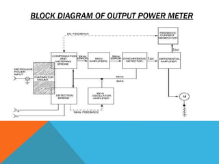
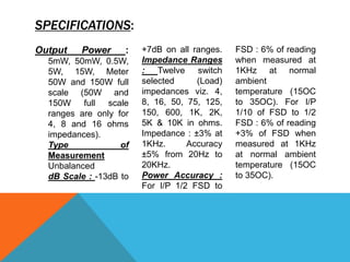
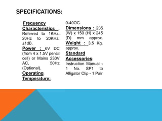
INTRODUCTION:
It measures directly the power
delivered by an audio frequency
circuit such as an amplifier to a
terminating load of known
impedances.
It is absorption type of audio
output power meter indicating the
power indicating the power
dissipation in the load in watt or
dB . The power meter has a wide
dynamic range i.e. from .1 mw to
50 watt, the dB indication is from -
13dB to +47 dB . It has fifteen
impedance ranges-
4,8,15,25,50,75,10,150,400,600,8
00,1k,2k,5k,10k ohms.
The instrument is simple in
design and the performance is
excellent. I consists of fifteen
switch selected resistors
corresponding to and very close
in tollerence to the impedance
ranges, which are connected
fifteen corresponding taps on a
current transformer of CRGO
laminations.
BLOCK DIAGRAM OF OUTPUT POWER METER
CIRCUIT DESCRIPTION
The power meter indirectly measures microwave frequency
power by using two bridge circuits—the detection bridge and
the compensation and metering bridge. The detection bridge
incorporates a 10-kilohertz (kHz) oscillator in which the
amplitude is determined by the amount of heating of the
thermistors(thermally variable resistor) in that bridge caused
by microwave power. The compensation and metering bridge
contains thermistors that are affected by the same microwave
power heating as those of the detection bridge.
CIRCUIT DESCRIPTION
An unbalance in the metering bridge produces a 10-kHz error
signal. This error signal, plus the 10-kHz bias that is taken
directly from the 10-kHz OSCILLATOR-AMPLIFIER, is mixed
in the SYNCHRONOUS DETECTOR. The synchronous
detector produces a dc current that is proportional to the 10-
kHz error signal. The error signal is fed back to the
compensation and metering bridge, where it substitutes for
the 10-kHz power in heating the thermistor and drives the
bridge toward a state of balance. The dc output of the
synchronous detector also operates the meter circuit for a
visual indication of power.
SPECIFICATIONS:
Output Power :
5mW, 50mW, 0.5W,
5W, 15W, Meter
50W and 150W full
scale (50W and
150W full scale
ranges are only for
4, 8 and 16 ohms
impedances).
Type of
Measurement
Unbalanced
dB Scale : -13dB to
+7dB on all ranges.
Impedance Ranges
: Twelve switch
selected (Load)
impedances viz. 4,
8, 16, 50, 75, 125,
150, 600, 1K, 2K,
5K & 10K in ohms.
Impedance : ±3% at
1KHz. Accuracy
±5% from 20Hz to
20KHz.
Power Accuracy :
For I/P 1/2 FSD to
FSD : 6% of reading
when measured at
1KHz at normal
ambient
temperature (15OC
to 35OC). For I/P
1/10 of FSD to 1/2
FSD : 6% of reading
+3% of FSD when
measured at 1KHz
at normal ambient
temperature (15OC
to 35OC).
SPECIFICATIONS:
Frequency
Characteristics :
Referred to 1KHz,
20Hz to 20KHz,
±1dB.
Power : 6V DC
(from 4 x 1.5V pencil
cell) or Mains 230V
AC, 50Hz
(Optional).
Operating
Temperature:
0-40OC.
Dimensions : 235
(W) x 150 (H) x 245
(D) mm approx.
Weight : 3.5 Kg.
approx.
Standard
Accessories:
Instruction Manual -
1 No. SP1 to
Alligator Clip - 1 Pair
APPLICATIONS:
Output power meters, although fairly new in the industry, have a
widespread application.
They are capable of measuring the power output of a generator
source such as an amplifier or oscillator by providing a large
selection of terminating impedances for such source and measuring
the voltage which is developed across such termination. With the
indicating meter calibrated to read in milli watts, it is possible to use
this instrument as a very rapid means of determining the power
delivered by any given generator source to any desired load, of
determining the impedance value of an unknown load, of determining
the proper impedance value of the load for maximum transfer of
energy, of determining the impedance versus frequency
characteristics of the generator source and/or with the connecting
transmission line, of determining the impedance versus frequency
characteristics of the existing load and of determining the proper
impedance value for a mismatched load when such circumstances
are desirable.
Output power meter

Output power meter

  • 2.
    INTRODUCTION: It measures directlythe power delivered by an audio frequency circuit such as an amplifier to a terminating load of known impedances. It is absorption type of audio output power meter indicating the power indicating the power dissipation in the load in watt or dB . The power meter has a wide dynamic range i.e. from .1 mw to 50 watt, the dB indication is from - 13dB to +47 dB . It has fifteen impedance ranges- 4,8,15,25,50,75,10,150,400,600,8 00,1k,2k,5k,10k ohms. The instrument is simple in design and the performance is excellent. I consists of fifteen switch selected resistors corresponding to and very close in tollerence to the impedance ranges, which are connected fifteen corresponding taps on a current transformer of CRGO laminations.
  • 3.
    BLOCK DIAGRAM OFOUTPUT POWER METER
  • 4.
    CIRCUIT DESCRIPTION The powermeter indirectly measures microwave frequency power by using two bridge circuits—the detection bridge and the compensation and metering bridge. The detection bridge incorporates a 10-kilohertz (kHz) oscillator in which the amplitude is determined by the amount of heating of the thermistors(thermally variable resistor) in that bridge caused by microwave power. The compensation and metering bridge contains thermistors that are affected by the same microwave power heating as those of the detection bridge.
  • 5.
    CIRCUIT DESCRIPTION An unbalancein the metering bridge produces a 10-kHz error signal. This error signal, plus the 10-kHz bias that is taken directly from the 10-kHz OSCILLATOR-AMPLIFIER, is mixed in the SYNCHRONOUS DETECTOR. The synchronous detector produces a dc current that is proportional to the 10- kHz error signal. The error signal is fed back to the compensation and metering bridge, where it substitutes for the 10-kHz power in heating the thermistor and drives the bridge toward a state of balance. The dc output of the synchronous detector also operates the meter circuit for a visual indication of power.
  • 6.
    SPECIFICATIONS: Output Power : 5mW,50mW, 0.5W, 5W, 15W, Meter 50W and 150W full scale (50W and 150W full scale ranges are only for 4, 8 and 16 ohms impedances). Type of Measurement Unbalanced dB Scale : -13dB to +7dB on all ranges. Impedance Ranges : Twelve switch selected (Load) impedances viz. 4, 8, 16, 50, 75, 125, 150, 600, 1K, 2K, 5K & 10K in ohms. Impedance : ±3% at 1KHz. Accuracy ±5% from 20Hz to 20KHz. Power Accuracy : For I/P 1/2 FSD to FSD : 6% of reading when measured at 1KHz at normal ambient temperature (15OC to 35OC). For I/P 1/10 of FSD to 1/2 FSD : 6% of reading +3% of FSD when measured at 1KHz at normal ambient temperature (15OC to 35OC).
  • 7.
    SPECIFICATIONS: Frequency Characteristics : Referred to1KHz, 20Hz to 20KHz, ±1dB. Power : 6V DC (from 4 x 1.5V pencil cell) or Mains 230V AC, 50Hz (Optional). Operating Temperature: 0-40OC. Dimensions : 235 (W) x 150 (H) x 245 (D) mm approx. Weight : 3.5 Kg. approx. Standard Accessories: Instruction Manual - 1 No. SP1 to Alligator Clip - 1 Pair
  • 8.
    APPLICATIONS: Output power meters,although fairly new in the industry, have a widespread application. They are capable of measuring the power output of a generator source such as an amplifier or oscillator by providing a large selection of terminating impedances for such source and measuring the voltage which is developed across such termination. With the indicating meter calibrated to read in milli watts, it is possible to use this instrument as a very rapid means of determining the power delivered by any given generator source to any desired load, of determining the impedance value of an unknown load, of determining the proper impedance value of the load for maximum transfer of energy, of determining the impedance versus frequency characteristics of the generator source and/or with the connecting transmission line, of determining the impedance versus frequency characteristics of the existing load and of determining the proper impedance value for a mismatched load when such circumstances are desirable.