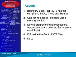
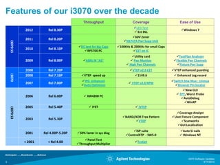
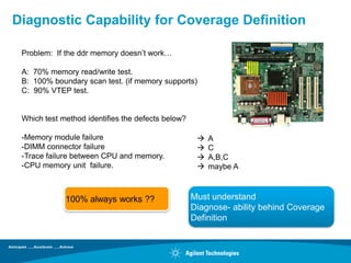
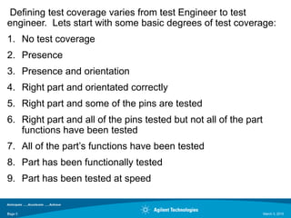
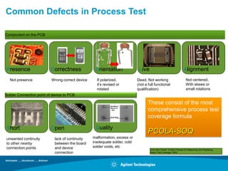
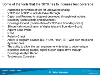
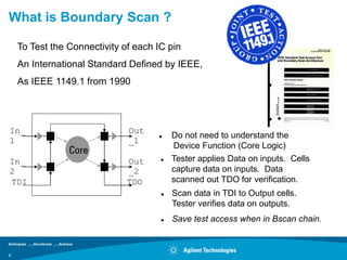
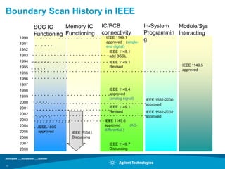
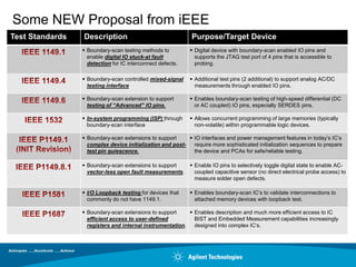
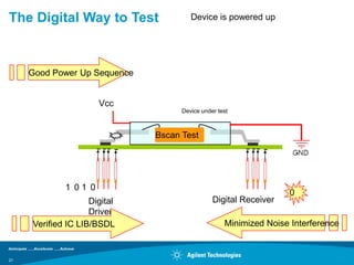
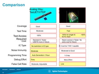
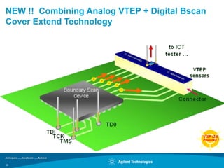
SlideShare a Scribd company logo
3070 User Group   IMPROVING TEST
       Meeting 2012   COVERAGE

                      Agilent Measurement System
                      Division
                      John Pendlebury
                      Applications Engineer

                      September 14, 2012


1
Agenda
    1. Boundary Scan Test (3070 has full
       compliant, BSDL, Tricks and Treats)
    2. CET for no access (example video
       memory device)
    3. Device programming (u Processors,
       Automotive board devices, Serial prom,
       nand flash)
    4. ISP inside the Control XTP Card
    5. DLLs


2
Features of our i3070 over the decade
                                              Throughput                      Coverage                     Ease of Use
                                                                             LED Test
               2012        Rel 8.30P                                                                       Windows 7
                                                                              Ext DLL
                                                                            60V Zener
               2011        Rel 8.20P
                                                                        N5747A Pwr Supp Unit
    i3070 S5


                                           DC test for big Caps    100KHz & 200KHz for small Caps
               2010        Rel 8.10P
                                              RP5700 PC                     CET on IC
                                                                            Utility card               TestPlan Analyzer
               2009        Rel 8.00P          ASRU N "AS"                  Pwr Monitor               Flexible Pwr Channels
                                                                          High Pwr Channels            Fixture Pwr Supp
               2008        Rel 7.20P                                        VTEP v2.0 CET            VTEP enhanced guarding
    i3070


               2008        Rel 7.10P         VTEP speed up                    1149.6                  Enhanced Log record
                                             IPG enhanced                                            Switch btw Mux : Unmux
               2007        Rel 7.00P                                        VTEP v2.0 NPM
                                             Auto Optimizer                                            Browser Pin locator
                                                                                                             New GUI
                                                                                                         FPY, Worst Probe
               2006        Rel 6.00P           XW4200 PC
                                                                                                            AutoDebug
                                                                                                              WinXP
               2005        Rel 5.40P               iYET                        iVTEP
    i3070 S3


                                                                                                        Coverage Analyst
                                                                       NAND/XOR Tree Pattern         User Fixture Component
               2003        Rel 5.30P
                                                                             VTEP                          Scanworks
                                                                                                         GUI Localization
                                                                             ISP suite                    Auto Si nails
               2001     Rel 4.00P-5.20P   50% faster in sys diag
                                                                         ControlXTP - SW5.0                Windows NT
                                               Panel Test
               < 2001     < Rel 4.00                                           Testjet
                                          Throughput Multiplier


                                                                                                                i3070 Software Updates
3                                                                                                                            9/14/2012
Diagnostic Capability for Coverage Definition

 Problem: If the ddr memory doesn‟t work…

 A: 70% memory read/write test.
 B: 100% boundary scan test. (if memory supports)
 C: 90% VTEP test.


 Which test method identifies the defects below?

 -Memory module failure                                A
 -DIMM connector failure                               C
 -Trace failure between CPU and memory.                A,B,C
 -CPU memory unit failure.                             maybe A


             100% always works ??                  Must understand
                                                   Diagnose- ability behind Coverage
                                                   Definition
Defining test coverage varies from test Engineer to test
engineer. Lets start with some basic degrees of test coverage:
1. No test coverage
2. Presence
3. Presence and orientation
4. Right part and orientated correctly
5. Right part and some of the pins are tested
6. Right part and all of the pins tested but not all of the part
   functions have been tested
7. All of the part‟s functions have been tested
8. Part has been functionally tested
9. Part has been tested at speed


Page 5
5                                                                  March 3, 2010
Common Defects in Process Test

Component on the PCB


                                                    +-               -+


Presence                  Correctness             Orientation               Live                                  Alignment

  Not presence            Wrong correct device     If polarized,           Dead, Not working                        Not centered,
                                                   it‟s revised or         (not a full functional                   With skews or
                                                   rotated                 qualification)                           small rotations
Solder Connection point of device to PCB

                                                                                  These consist of the most
                                                                                  comprehensive process test
                                                                                  coverage formula

Short                     Open                    Quality
                                                                                  PCOLA-SOQ
unwanted continuity         lack of continuity   malformation, excess or
to other nearby             between the board    inadequate solder, cold
connection points           and device           solder voids, etc
                                                                                   From Ken Parker “A New Process for Measuring and Displaying
                            connection                                             Board Test Coverage”.2002
Some of the tools that the 3070 has to increase test coverage
•        Automatic generation of test for unpowered analog.
•        VTEP and IVTEP to include Drive Through
•        Digital and Powered Analog test developed through test models
•        Boundary-Scan (simple and advanced)
•        Coverage Extend (combination of VTEP and Boundary-Scan)
•        Silicon Nails (combination of digital test and Boundary-Scan).
•        Agilent Bead Probe
•        NPM
•        Polarity Check
•        Ability to program devices (EEPROM, Flash, ISP) with both static and
         dynamic data.
•        The ability to allow the test engineer to write tests to cover unique
         situations (analog cluster, digital cluster, digital drive through)
•        Coverage Analyst Report
•        Test Access Consultant


                                                                     Measurement Systems Division

Page 7
7                                                                                January 24, 2007
What is Boundary Scan ?

    To Test the Connectivity of each IC pin
    An International Standard Defined by IEEE,
    As IEEE 1149.1 from 1990


In_                           Out
                                         Do not need to understand the
1                             _1
                Core                      Device Function (Core Logic)
In_                           Out        Tester applies Data on inputs. Cells
2                             _2          capture data on inputs. Data
TDI                           TDO         scanned out TDO for verification.
                                         Scan data in TDI to Output cells.
                                          Tester verifies data on outputs.
                                         Save test access when in Bscan chain.


8
Why IEEE 1149.1 ?

                                 What is the challenge ?
    IEEE, approved 1149.1       What is the solution?
    In 1990


                            ?

                                   We Talk About IEEE 1149.1
What is IEEE1149.1?
                                   In 2012
 Where is IEEE1149.1 used ?

9
The Industry Challenges for Process Test

*                                      *


Intel Testing Forum 2008 at Taipei :

Challenges: Smaller Size, HDI, High Speed Signal Trace
     Results:                                             *
     No Space for Test Access
     Traditional Test Pad create distortion in high speed signal

                                        *:   Picture from Intel Testing Forum 2008 Taipei
                                                                                            *
10
Boundary Scan History in IEEE
             SOC IC      Memory IC   IC/PCB              In-System  Module/Sys
             Functioning Functioning connectivity        Programmin Interacting
     1990    ....................... ..IEEE 1149.1
                                                         g
                                       approved (single-
     1991    ......                    end digital)
     1992
     1993    . . . . . . . . . . . . . . . . . . . . . . . . . IEEE 1149.1
                                                                    add BSDL
     1994   .. .. .. .. .. .. . . . . . . . . . . . . . . . . . . . IEEE 1149.1
                                                                                                             IEEE 1149.5
     1995   . . . . . . . . . . . . . . . . . . . . . . . . . Revised. . . . . . . . . . . . . . . . . . .
            .....                                                   ....                                     approved
     1996
     1996   ............
     1997
     1998                                                      IEEE 1149.4
     1999
            ...... ..................                         .approved
                                                                .
                                                               (analog signal)
     2000   . .. .. .. .. . . . . . . . . . . . . . . . . . . . . . . . . . . . . . . . .IEEE 1532-2000
                                                                                           approved
                                                                     IEEE 1149.1
     2001    . . . . . . . . . . . . . . . . . . . . . . . . .Revised
                                                                                           IEEE 1532-2002
     2002
             . .. .. .. .. .. . . . . . . . . . . . . . . . . . . . . . . . . . . . . . . .approved
     2003    . . . . . . . . . . . . . . . . . . . . . . . IEEE 1149.6
                ...........                                      ..
     2004    . .IEEE.1500
                   .. ..                                         approved        (AC-
     2005           ..
                  approved                  IEEE P1581
                                                                 differential )

     2006                             Discussing
     2007                                                      IEEE 1149.7
     2008                                                      Discussing


11
Some NEW Proposal from iEEE
Test Standards   Description                                 Purpose/Target Device
                  Boundary-scan testing methods to          Digital device with boundary-scan enabled IO pins and
                   enable digital IO stuck-at fault           supports the JTAG test port of 4 pins that is accessible to
                   detection for IC interconnect defects.     probing.

                  Boundary-scan controlled mixed-signal     Additional test pins (2 additional) to support analog AC/DC
                   testing interface                          measurements through enabled IO pins.

                  Boundary-scan extension to support        Enables boundary-scan testing of high-speed differential (DC
                   testing of “Advanced” IO pins.             or AC coupled) IO pins, especially SERDES pins.

                  In-system programming (ISP) through       Allows concurrent programming of large memories (typically
                   boundary-scan interface                    non-volatile) within programmable logic devices.

                  Boundary-scan extensions to support      IO interfaces and power management features in today‟s IC‟s
                   complex device initialization and post-   require more sophisticated initialization sequences to prepare
                   test pin quiescence.                      the device and PCAs for safe/reliable testing.

                  Boundary-scan extensions to support       Enable IO pins to selectively toggle digital state to enable AC-
                   vector-less open fault measurements.       coupled capacitive sensor (no direct electrical probe access) to
                                                              measure solder open defects.

                  I/O Loopback testing for devices that     Enables boundary-scan IC‟s to validate interconnections to
                   commonly do not have 1149.1.               attached memory devices with loopback test.

                  Boundary-scan extensions to support      Enables description and much more efficient access to IC
                   efficient access to user-defined          BIST and Embedded Measurement capabilities increasingly
                   registers and internal instrumentation.   designed into complex IC‟s.
DFT for Boundary Scan Test
Rule #1 TCK Pull-Down, TMS Pull-Up
Rule #1.1: Pull-down R for TCK.                                                                                          Bscan
                                                                                                                         Cells
        Connect TCK through 100 ohm resistor to
        Ground. For low voltage logic(<1.5volt),
        The Designer may use 50 ohm resistor.
                                                                                              Core
                                                                           +Vcc               Logic                    +Vcc
Rule #1.2: Pull-Up R for TMS.

       Connect TMS through 1.2Kohm pull up
       resistor to high.
Note1: The TDI, TDO, are also suggested to have proper pull-up
                                                                           R                TEST ACCESS
                                                                                                                          R
       resistor to Vcc, So to have a stable input and output signal. The                    PORT
       Resistor could be 100 or 50ohm as TCK. Or other values, like
       several K ohms.
                                                                            TDI
                                                                                            CONTROLLER
                                                                                            (TAP)
                                                                                                                         TDO
Note 2: If TRST# is used here, A high R ( like 1.2K or even higher ) to
        Vcc can be used here . Some ICs may use pull-down resistor.
        In that case, user needs to keep TRST# in high during bscan            +Vcc
        testing.                                                                                          TCK
Note3 : User may reference the IC Design Document to see the exact                    TMS
        resistor suggestion from the IC designer. Generally, the pull-Up
        resistor is recommended from many ICs. But some will require                                      100 or 50
        a pull-down R instead. Be sure to reference the design-guide
        document..                                                                 1.2K                   Ohm
Note4: User can consider to change the value of pull-up/down resistor              Ohm
                                                                                  TRST#
        here, The value of resistors may impact the overall power
        consumption. Lower value resistor requires stronger external
        driver capability. Pay attention here when changing test
        platform.                                                                 1.2K                                Test
                                                                                  Ohm                                 Access
13
DFT for Boundary Scan Test
Rule #2 Chain Boundary Scan Devices in Order
Rule #2.1: TDO connects to TDI in serial

       Connect 1st Boundary IC’s TDO to 2nd
       Boundary IC’s TDI , 2nd IC’s TDO to 3rd IC’s                      U1
       TDI…etc.

                                                                                                   U3
Rule #2.2: TCK , TMS connects in parallel                                               U2
       Connect all TCK and TMS in parallel.                              TDI TDO       TDI TDO     TDI TDO
                                                                         TCK TMS       TCK   TMS   TCK TMS


Note1: In some cases, when the board designer has more
       flexibilities in layout arrangement and if there is a new,
       unverified Boundary IC, We suggest to put this IC be end of
       the Bscan chain.

Note2: For any IC, It‟s good to keep TDI away from TDO to avoid
       possible “short” between TDI/TDO.          Board designer
       may consider to keep a proper distance under the overall
       space consideration.

Note3: If more ICs in the chain, The TCK, TMS propagation may not                   #2.2
       be effective as in lesser-IC-chain. In that Case, User may
       consider to put Buffer Circuitry for TCK/TMS, To get a better
       TCK/TMS synchronization.                                        #2.1         TCK-TMS
                                                                       TDO-TDI in   in parallel
                                                                       serial

14
DFT for Boundary Scan Test
Rule #3 Level Shifter When Different Logic Level
Rule #3.1: Test Access on EVERY TDI, TDO, TCK,
     TMS
      Test Access on EVERY TDI, TDO, TCK, TMS.
      (and TRST if the IC has TRST pin)                           U1
      This is a MUST request for debug-purpose.
                                                                                                     U3
      If possible, Put one access in interconnect
      pins, This can help to understand the out-                                   U2
      putting signal situation when debugging the
      interconnect test.                                          TDI TDO         TDI TDO           TDI TDO
                                                                  TCK TMS         TCK   TMS         TCK TMS


Rule #3.2 : Check IC’s Logic Level
      Put Level Shifter between ICs, If the ICs
      operate in different logic level. Don’t forget to
      put the TAP(TDI, TDO, TMS, TCK) pins into
      Logic-level shifter
                                                                            #3.1              #3.2
Note : When we have >3 ICs in the chain, We may consider to
                                                                            Test Access        Logic
       put jumpers in middle ICs TDI,TDO pins. This can help to
       bypass not-working Bscan IC, and still make the whole                for TAP,          Level
       chain work.                                                          and One           shifter
      If putting a jumper on the board is not allowed, The ICT    Level     access in         when ICs
      engineer can put a GP relay or direct wiring inside the
      fixture to bypass the middle IC.                            shifter   interconnect      in different
                                                                            pins              logic levels.
15
DFT for Boundary Scan Test
 Rule #4 Additional Access from BSDL
Rule #4.1: Special Access for
    Compliance_Patterns from BSDL
    file
       Some ICs have special enabling
      pins, These pins can be found in
      BSDL file. Search
      “Compliance_Patterns”. To see what
      pins need to be triggered for
      smoothly turn-on Bscan mode.
      In this example, The nodes:
        PWRGOOD, DPRSTPB,
      Need Test Access for keeping “high”
Rule #4.2: Special requirements in
    DESIGN_WARNING message
       1149.1 allows IC to have special
      notes in BSDL with
      DESIGN_WARNING message, User
 16   needs to check this message to see
DFT for Boundary Scan Test
Rule #5 Access for Disabling Surrounding Devices
Rule #5: Access for Disabling
    Surrounding Device

                                                                                TDI

      Experience showed :Without                                     Bscan IC   TDO
                                                                                TCK
     disabling the surrounding devices,
                                                                                TMS
     especially the CLK generator, the                               CLK
     Boundary IC sometimes, can not
     function under Bscan mode. Or
     functioning with                                    CLK Gen
                                               R
     unstable/unpredictable errors.                      POWER_disable

      Therefore, We recommend to
     disable the surrounding devices,
     especially the “Clock Generator”.             Access here to Disable
                                                   CLK Gen
      For the disable pin, the designer
     need to put      pull-up (or pull-down)
     resistor and a test access on it.

17
DFT for Boundary Scan Test
Rule #6 Bscan Access on Bottom-Side
Rule #6:Pull BScan Access on Bottom-                          Not Probe from Upper Side
    Side of the Board
       Put the TDI, TDO, TCK, TMS,
     TRST access on Bottom-Side of the
     board, So that these pins will be
     probed from bottom part of the
     fixture.
      Due to shorter signal path and not-
     through transfer-pins, probing from
     bottom part of the fixture will have a
     better signal integrity, and more
     accurate for the probe to hit the test
                                                               TDI TDO TCK TMS TRST
     pad.
      Experience showed: Probing TAP                          Probe from Bottom Side
     pins from bottom side, will result in a   TAP access should be Test Pad, Do NOT thru Via hole,
     more stable Bscan Testing.                Test Pad size should >30mils at least; with 100mils probe

      Some Bscan Validation “Connector”
18   need to be on top side, That will be a
VTEP Family Innovation
                                               Connector High Speed
 Year       Innovation   SW                                         No Test Access
                         Version      IC       Signal Pin Connector
                                   (Sensitivit (Sensitivity)        Solution
                                                           GND Pin
 1993       TestJET                y)
                                    YES        YES
                                    >20fF      >20fF

 2003        VTEP                   YES        YES
                          5.3
                                    >5fF       >5fF

 2005        iVTEP                  YES        YES
                          5.42
                                    <5fF       >5fF


 2007       VTEP v2.0               YES        YES
                         7.0                              YES
              NPM                   <5fF       >5fF

 2008                               YES        YES
        VTEP v2.0 Powered 7.2                             YES        YES
           Cover-Extend             <5fF       >5fF


19
TestJET vs VTEP


     MDA with                                                        I1000 with
     TestJET                                                         VTEP(iVTEP)

     ICs:                                                            ICs:

     Tested Pins: 482                                                Tested Pins: 1168
     Testable:    1201                                               Testable:    1201
     Coverage:41%              Coverage       2.36x better           Coverage:97%

     Connectors:                                                     Connectors:

     Tested Pins: 260                                                Tested Pins: 445
                                              VTEP
                                              σ = 0.3                Testable:    450
     Testable:    450
     Coverage:58%                                                    Coverage:98%
                                                 Testjet
                                                   σ = 1.7           DDR2 :Vcc/GND covered
                                                                     sATA :Vcc/GND covered


     Note: Testable pins =Total pins –Vcc-GND- No Access- same nail pins

20
The Digital Way to Test                 Device is powered up


     Good Power Up Sequence


                      Vcc
                                     Device under test


                              Bscan Test
                              Tree Test Lib
                              Function


             1 01 0
                                                                   0
                    Digital                     Digital Receiver
                    Driver
     Verified IC LIB/BSDL                           Minimized Noise Interference


21
Comparison
                          Analog Way:                  Digital Way: Boundary
                          TestJET/VTEP                 Scan


             Coverage             Good                           Good


             Test Time            Moderate                        Fast

                                  100%                    100% for single IC       <50%
         Test Access                                      for IC chain
           Required          Standard in Tester           Need License in Tester No
                  Cost       USD1K more in fixture        extra cost for fixture

               IC Type     No restriction in IC type   IC must be 1149.1-capable

       Noise Immunity      Moderate                      Moderate to Good

     Programming Time       Auto Generation <1hour             1-2 day

          Debug Effort     Easy                                More Effort

        False Call Rate    Moderate, Adjustable          Low


22
NEW !! Combining Analog VTEP + Digital Bscan
Cover Extend Technology
Extend Bscan Coverage from
Bscan IC to Adjacent Non-Bscan Device                   to ICT tester …


                                                                    VTEP
                                                                    sensors

                    Boundary Scan
                    device
                                                              Connector or
                                                              other device
                                          Remove Test Access
                                    TD0
              TDI
                TCK
                  TMS                     Test Access pins


23
Increasing Test   In-System Programmable
Coverage at ICT   Device Solutions
What is ISP?

The term In-System Programming (ISP) refers to
programming of programmable devices after they are
soldered onto a PC board.

This includes both FLASH and Programmable Logic
Devices (PLDs) as well as other devices.


25
FLASH & PLD market growth
                          20                                                                        3.5


                          18
                                                                                                    3
                          16


                          14                                                                        2.5
     Dollars (Billions)


                          12


                                                                                                          Units (Billions)
                                                                                           WOW !
                                                                                                    2

                          10

                                                                                                    1.5
                           8


                           6                                                                        1

                           4
                                                                                                    0.5
                           2


                           0                                                                        0
                               2009     2010           2011          2012         2013       2014

                                               PLD $   FLASH $   PLD Units   FLASH Units


                                Flash memory is now found in 70% of PCBA‟s built today.

26
In-System Programming Profile

• Flash memory devices are used on more than 70% of PCBA‟s
  manufactured today.
• Programmable Logic Devices (PLD, CPLD, SPLD, FPGA are
  used on more than 40% of PCBAs manufactured today.
• Usage for both is growing rapidly.
• Logistics issues are driving manufacturer‟s to program these
  devices after mounting onto PCBA‟s (In-System
  Programming).
     •   Rapid production turn-around (time-to-market).
     •   Reduced inventory.
     •   Facilitate engineering changes.
     •   Post manufacturing repair and reprogramming.


27
What ISP Devices Can We Address with i3070?


     Type of Device          Programmable on the i3070?
     FLASH                   YES.
     EPROMs/PROMs            YES. But requires extra voltages on the
                             board.
     CPLDs                   YES.
     FPGA (RAM based)        YES, but why would you want to do this?

     Configuration EEPROMS   YES.
     Serial EEPROMs          YES.
     PAL/GAL                 YES, but it depends on the device.


28
Description of Flash ISP features
     • Support of larger devices (>256Mbit)
     • Much faster first run time than Flash70
     • Faster mature run time than Flash70
     • Much smaller object file size
     • Much less testhead memory required
     • No dependency between repeat loop count and segment size.
     • Automatic repeat loop (go until end of data).
     • Flag bad checksums on data records (S-record and Intel Hex)
     • Summary information of data image compilation:
       – The number of bytes programmed
       – The number of bytes stripped (“FF stripping”)
       – The total number of segments
       – Compiler flags turned-on or off
       – The Minimum and Maximum addresses used


29
Example of Summary Information


30
Description of PLD ISP features


     • Ability to program PLDs directly from:
       – Serial Vector Format (SVF) file
       – Standardized Test And Programming Language (STAPL) file
       – Jam file
       – Jam Byte Code (JBC) file
     • No need to convert to PCF/VCL file(s).
     • Much Faster compile time.
     • Much less files to keep track of: VCL file plus data file.
     • Single test programming - no resistors in the fixture.
     • Print statements in Jam or STAPL files will output to BT-Basic window.
     • We can now program “non-F” Altera parts.


31
Block Diagram showing Flash ISP Memory


                                                                      Vector Ram
                                Sequence
                                Ram


                                                                      Vector Ram


                                                       MUX
             Directory Ram


                                Sequence
                                Ram                                   Vector Ram


                       Data
      i3070                                Items in BLUE are found only in
                       Translation
      Image Data
                       Acceleration        Control XTP card.


32
How do we do it? FLASH

     Flash Software paradigm:
     • Pass address/data image file to testhead with programming algorithm
       information (we now have a Flash “Player”).
     • Results in MUCH smaller object file and, as a result, less time required
       for first run time download.
     • Changed method of downloading image and object files to testhead by
       bypassing the system card.
     • New software structure allows for easier support of new data file
       formats and Flash data image manipulation.
     • Two compiles happen “Behind the scenes” :
       – Convert data format to i3070 image
       – Create i3070 programming algorithm object file


33
VCL syntax - Example of Flash ISP
flash isp ! Instead of “flash”        unit
assign Data_Bus to pins 4,3,2,1 ...     execute V1
. . .                                   segment hexadecimal “400”
vector V1                                  repeat ! Automatic Loop
   set . . .                                 execute V2 drive data Addr
end vector                                   execute V2 drive data My_Data
. . .                                        execute Write
flash assignments                            execute End_Cycle
    file “1Mx8.data” srecord                 homingloop
    data My_Data to groups Data_Bus             execute RY_Done exit if pass
    address Addr to groups Addr_Bus          end homingloop
    eod reuse                                next Addr
end flash assignments                        next My_Data
. . .                                      end repeat
                                       end segment
                                      end unit


34
Process to convert existing Flash70 test
     to new Flash ISP test

     1. Enable the Flash ISP software in the config file (enable flash isp).
     2. Make a backup copy of the original file!
     3. Change „flash‟ keyword to „flash isp‟.
     4. Change „data/end data‟ block to „flash assignments‟ block:
         a.   Change the „file‟ statement to new syntax.
         b.   Point to Data bus group with „data‟ statement.
         c.   Point to Address bus group with „address‟ statement.
         d.   Make sure the “end-of-data” action is defined.
     As long as you do not have multiple different vectors trying to drive
     address or data, you should now be done (see “Limitations” section).


35
Limitations - Flash ISP

     • Address bus width limited to 32-bit (4G addresses)
     • Data bus width limited to 128-bit if drive or receive data only or 64-bit if
       both drive and receive data (i.e., Data Polling).
     • Cannot drive Address and Data on the same vector (example, execute
       V1 drive data Address drive data Data).
     • Cannot have different vectors to drive address or data (e.g., execute
       V1 drive data Data, execute V2 drive data Data).
     • Entire Flash image must reside in testhead memory.
     • Cannot handle parameter passing (i.e., serial number, NIC, etc.).
     • Only one “flash assignments” block per test. This means only one data
       file can be accessed.


36
Success Factors for Programming


     1. Make sure you have proper testability:
         •   Full access for Flash and disable nodes
         •   Easy disable methods
     2. Use Ground Plane in the fixture.
     3. Specify TAP pins with “Critical” attribute in Board Consultant!
     4. Make sure PLD programming data files were generated with Bscan
        chain defined. You can download the programs to create the
        SVF/Jam/STAPL files from the PLD vendor‟s web sites.
     5. Remember, if you have an ECO to the data file for Flash ISP, you
        must recompile with the new data file.


37
Questions and Answers


                                  Agilent Restricted
                                        March 2009
Page 38
39
Typical Debug Problems on Boundary Scan

     •Ground Bounce
     •Bad BSDL data file
     •Topology Errors (from CAD translation)
     •Standard Digital disabling problems


                                               From Mike Farrell


40                                                                 Page 40
Ground Bounce Debug


 Ground Bounce
 • Cause: too many pins change state at once for the board and fixture‟s power &
   ground capability
   (Note: Use short wire fixtures with good grounding.)
   The board “ground” node spikes relative to tester ground which creates a signal
   spike at clock inputs.
   State machine jumps ahead due to unexpected spikes on clock input
 • Break up into tests with fewer pins transitioning – Max Connect option
 • Ground bounce suppression option
 • Potential issue of noise on the board – Voltage regulators one source.
 • Ground plane is a good choice for helping with this problem.
 • Twisted pair wiring might be needed.
 • Time for a scope on the TCK line.
                                                                  From Mike Farrell


41                                                                                    Page 41
Potential Problems With BSDL Files
     •The BSDL will not compile due to syntax issue(s)
     •Wrong boundary-scan register length – number of cells in the chain.
     •Wrong ID code value.
     •Pin order for a section is wrong (reversed).
     •The BSDL file does not match the actual silicon.
     •The part is non complicate with the 1149 standard – may require special
     vectors or pins to allow the boundary-scan section to work
     •The part has multiple boundary-scan chains internal to the part. Seeing
     more and more of this.
     •Wrong cell type assigned to the associated pin.
     •Instruction code is wrong.
     •Wrong or older BSDL file is being used.

                                                            From Mike Farrell


42                                                                              Page 42
1149.6 – AC Signal Detection


                From IEEE Document “1149.6 IEEE Standard for Boundary Scan Testing of Advanced Digital Networks


     - Coverage on AC-coupled differential signals
     - Compliant to the IEEE 1149.6 standard
     - More designs are going hi-speed (> GHz) eg DDR3
     - Uses more of these type of architecture
     Capacitors tested for presence
     Traces and pins tested for connectivity                                                                      From Mike Farrell


43                                                                                                                                    Page 43
Benefits of Advance Boundary-Scan
 •Quick and easy way to generate test model for complex device.
 •Use an industrial standard (1149).
 •Ability to break large devices into multiple tests to reduce test resource
 requirements.
 •Ability to chain number of devices together and test with a standard
 method.
 •When boundary-scan devices are chained, a method to help gain test
 coverage with reduced test access.
 •Programming ISP devices.
 •Potential to testing non boundary-scan devices with silicon nails.
 •Coverage Extend
 •Potential for running built in self test (BIST).
 •Will start seeing chips with built in measuring devices (embedded) that
 will be controlled by boundary-scan.
 •Potential for testing high speed lines with capacitance coupling (1149.6).


                                                           From Mike Farrell


44                                                                             Page 44

More Related Content

What's hot

IOTC08 The Arduino Platform
IOTC08 The Arduino PlatformIOTC08 The Arduino Platform
IOTC08 The Arduino Platform
Eoin Brazil
 
ADF4113 Frequency Synthesizer 驅動程式實作
ADF4113 Frequency Synthesizer 驅動程式實作ADF4113 Frequency Synthesizer 驅動程式實作
ADF4113 Frequency Synthesizer 驅動程式實作
Simen Li
 
PyconKR 2018 Deep dive into Coroutine
PyconKR 2018 Deep dive into CoroutinePyconKR 2018 Deep dive into Coroutine
PyconKR 2018 Deep dive into Coroutine
Daehee Kim
 
LCD Theory and Working Principles
LCD Theory and Working PrinciplesLCD Theory and Working Principles
LCD Theory and Working Principles
Robo India
 
Analysis and design of a low voltage and low power double tail comparator
Analysis and design of a low voltage and low power double tail comparatorAnalysis and design of a low voltage and low power double tail comparator
Analysis and design of a low voltage and low power double tail comparator
Ushaswini Chowdary
 
ARM and SoC Traning Part I -- Overview
ARM and SoC Traning Part I -- OverviewARM and SoC Traning Part I -- Overview
ARM and SoC Traning Part I -- Overview
National Cheng Kung University
 
Arduino - iniciação à linguagem C (servomotores)
Arduino - iniciação à linguagem C (servomotores)Arduino - iniciação à linguagem C (servomotores)
Arduino - iniciação à linguagem C (servomotores)
Ana Carneirinho
 
Xdp and ebpf_maps
Xdp and ebpf_mapsXdp and ebpf_maps
Xdp and ebpf_maps
lcplcp1
 
Multi-KilowattFlybackConverters.pptx
Multi-KilowattFlybackConverters.pptxMulti-KilowattFlybackConverters.pptx
Multi-KilowattFlybackConverters.pptx
RickMaity
 
[ZigBee 嵌入式系統] ZigBee Architecture 與 TI Z-Stack Firmware
[ZigBee 嵌入式系統] ZigBee Architecture 與 TI Z-Stack Firmware[ZigBee 嵌入式系統] ZigBee Architecture 與 TI Z-Stack Firmware
[ZigBee 嵌入式系統] ZigBee Architecture 與 TI Z-Stack Firmware
Simen Li
 
Ejercicios Java
Ejercicios JavaEjercicios Java
Ejercicios Java
Estefy Sanchez
 
Metal Detector Project
Metal Detector ProjectMetal Detector Project
Metal Detector Project
Danish Bangash
 
射頻電子 - [實驗第四章] 微波濾波器與射頻多工器設計
射頻電子 - [實驗第四章] 微波濾波器與射頻多工器設計射頻電子 - [實驗第四章] 微波濾波器與射頻多工器設計
射頻電子 - [實驗第四章] 微波濾波器與射頻多工器設計
Simen Li
 
Arduino Workshop
Arduino WorkshopArduino Workshop
Arduino Workshop
atuline
 
半導體製程
半導體製程半導體製程
半導體製程
zhchenwin
 
Phase-locked Loops - Theory and Design
Phase-locked Loops - Theory and DesignPhase-locked Loops - Theory and Design
Phase-locked Loops - Theory and Design
Simen Li
 
111-1 SIMPLIS教學_20220630.pdf
111-1 SIMPLIS教學_20220630.pdf111-1 SIMPLIS教學_20220630.pdf
111-1 SIMPLIS教學_20220630.pdf
ssuser1be9ce
 
Introduction to Kinect - Update v 1.8
Introduction to Kinect - Update v 1.8Introduction to Kinect - Update v 1.8
Introduction to Kinect - Update v 1.8
Matteo Valoriani
 

What's hot (18)

IOTC08 The Arduino Platform
IOTC08 The Arduino PlatformIOTC08 The Arduino Platform
IOTC08 The Arduino Platform
 
ADF4113 Frequency Synthesizer 驅動程式實作
ADF4113 Frequency Synthesizer 驅動程式實作ADF4113 Frequency Synthesizer 驅動程式實作
ADF4113 Frequency Synthesizer 驅動程式實作
 
PyconKR 2018 Deep dive into Coroutine
PyconKR 2018 Deep dive into CoroutinePyconKR 2018 Deep dive into Coroutine
PyconKR 2018 Deep dive into Coroutine
 
LCD Theory and Working Principles
LCD Theory and Working PrinciplesLCD Theory and Working Principles
LCD Theory and Working Principles
 
Analysis and design of a low voltage and low power double tail comparator
Analysis and design of a low voltage and low power double tail comparatorAnalysis and design of a low voltage and low power double tail comparator
Analysis and design of a low voltage and low power double tail comparator
 
ARM and SoC Traning Part I -- Overview
ARM and SoC Traning Part I -- OverviewARM and SoC Traning Part I -- Overview
ARM and SoC Traning Part I -- Overview
 
Arduino - iniciação à linguagem C (servomotores)
Arduino - iniciação à linguagem C (servomotores)Arduino - iniciação à linguagem C (servomotores)
Arduino - iniciação à linguagem C (servomotores)
 
Xdp and ebpf_maps
Xdp and ebpf_mapsXdp and ebpf_maps
Xdp and ebpf_maps
 
Multi-KilowattFlybackConverters.pptx
Multi-KilowattFlybackConverters.pptxMulti-KilowattFlybackConverters.pptx
Multi-KilowattFlybackConverters.pptx
 
[ZigBee 嵌入式系統] ZigBee Architecture 與 TI Z-Stack Firmware
[ZigBee 嵌入式系統] ZigBee Architecture 與 TI Z-Stack Firmware[ZigBee 嵌入式系統] ZigBee Architecture 與 TI Z-Stack Firmware
[ZigBee 嵌入式系統] ZigBee Architecture 與 TI Z-Stack Firmware
 
Ejercicios Java
Ejercicios JavaEjercicios Java
Ejercicios Java
 
Metal Detector Project
Metal Detector ProjectMetal Detector Project
Metal Detector Project
 
射頻電子 - [實驗第四章] 微波濾波器與射頻多工器設計
射頻電子 - [實驗第四章] 微波濾波器與射頻多工器設計射頻電子 - [實驗第四章] 微波濾波器與射頻多工器設計
射頻電子 - [實驗第四章] 微波濾波器與射頻多工器設計
 
Arduino Workshop
Arduino WorkshopArduino Workshop
Arduino Workshop
 
半導體製程
半導體製程半導體製程
半導體製程
 
Phase-locked Loops - Theory and Design
Phase-locked Loops - Theory and DesignPhase-locked Loops - Theory and Design
Phase-locked Loops - Theory and Design
 
111-1 SIMPLIS教學_20220630.pdf
111-1 SIMPLIS教學_20220630.pdf111-1 SIMPLIS教學_20220630.pdf
111-1 SIMPLIS教學_20220630.pdf
 
Introduction to Kinect - Update v 1.8
Introduction to Kinect - Update v 1.8Introduction to Kinect - Update v 1.8
Introduction to Kinect - Update v 1.8
 

Viewers also liked

4 bit cmos full adder in submicron technology with low leakage and groun...
4 bit  cmos  full  adder  in submicron  technology with low leakage and groun...4 bit  cmos  full  adder  in submicron  technology with low leakage and groun...
4 bit cmos full adder in submicron technology with low leakage and groun...
shireesha pallepati
 
Kompetenzentwicklung für Content-Strategie #cosca16
Kompetenzentwicklung für Content-Strategie #cosca16Kompetenzentwicklung für Content-Strategie #cosca16
Kompetenzentwicklung für Content-Strategie #cosca16
Kai Heddergott
 
HathiTrust Research Center Data Capsule Overview 09.10.14
HathiTrust Research Center Data Capsule Overview 09.10.14HathiTrust Research Center Data Capsule Overview 09.10.14
HathiTrust Research Center Data Capsule Overview 09.10.14
Robert H. McDonald
 
Vilde Urbans area
Vilde Urbans area Vilde Urbans area
Vilde Urbans area
SofiaNim
 
Presentación diego miranda candidato decano. debate profesores
Presentación diego miranda candidato decano. debate profesoresPresentación diego miranda candidato decano. debate profesores
Presentación diego miranda candidato decano. debate profesores
dmirandal01
 
Impuestos
ImpuestosImpuestos
Impuestos
antoniomanfredi
 
SEOGuardian - Plantas Online en Espanya
SEOGuardian - Plantas Online en EspanyaSEOGuardian - Plantas Online en Espanya
SEOGuardian - Plantas Online en Espanya
Bint
 
Aprender a jugar al poker
Aprender a jugar al pokerAprender a jugar al poker
Aprender a jugar al poker
pokerdekk
 
Si no estoy en Twitter no me conoce ni el Tato
Si no estoy en Twitter no me conoce ni el TatoSi no estoy en Twitter no me conoce ni el Tato
Si no estoy en Twitter no me conoce ni el Tato
Elia Méndez Bravo
 
Camino a los yungas
Camino a los yungasCamino a los yungas
Camino a los yungas
jazz_3c
 
Internet of Things, Cloud & Co.
Internet of Things, Cloud & Co.Internet of Things, Cloud & Co.
Internet of Things, Cloud & Co.
Damir Dobric
 
Folleto Proxima Generación de Linóleo
Folleto Proxima Generación de Linóleo Folleto Proxima Generación de Linóleo
Folleto Proxima Generación de Linóleo
Forbo Pavimentos, S.A.
 
Dekra insight safety excellence symposium
Dekra insight safety excellence symposiumDekra insight safety excellence symposium
Dekra insight safety excellence symposium
Musallam Khaifi
 
Harun Yahya Islam Eternity Has Already Begun
Harun Yahya Islam   Eternity Has Already BegunHarun Yahya Islam   Eternity Has Already Begun
Harun Yahya Islam Eternity Has Already Begun
zakir2012
 
VI Congreso Biobancos 2015
VI Congreso Biobancos 2015VI Congreso Biobancos 2015
VI Congreso Biobancos 2015
fundacioudl
 
Carretera de Apurimac 2
Carretera de Apurimac 2Carretera de Apurimac 2
Carretera de Apurimac 2
Estudio Ingeniería Civil
 
Geomagz201401
Geomagz201401Geomagz201401
Geomagz201401
Eko Kiswanto
 
Kolab - Groupware unlike others
Kolab - Groupware unlike othersKolab - Groupware unlike others
Kolab - Groupware unlike others
Christoph Wickert
 
Resultate elternumfrage neue medien ps buerglen
Resultate elternumfrage neue medien ps buerglenResultate elternumfrage neue medien ps buerglen
Resultate elternumfrage neue medien ps buerglen
Emanuel Schönholzer
 
La Justicia Juvenil en Catalunya
La Justicia Juvenil en CatalunyaLa Justicia Juvenil en Catalunya
La Justicia Juvenil en Catalunya
Francisco J. Estrada Vásquez
 

Viewers also liked (20)

4 bit cmos full adder in submicron technology with low leakage and groun...
4 bit  cmos  full  adder  in submicron  technology with low leakage and groun...4 bit  cmos  full  adder  in submicron  technology with low leakage and groun...
4 bit cmos full adder in submicron technology with low leakage and groun...
 
Kompetenzentwicklung für Content-Strategie #cosca16
Kompetenzentwicklung für Content-Strategie #cosca16Kompetenzentwicklung für Content-Strategie #cosca16
Kompetenzentwicklung für Content-Strategie #cosca16
 
HathiTrust Research Center Data Capsule Overview 09.10.14
HathiTrust Research Center Data Capsule Overview 09.10.14HathiTrust Research Center Data Capsule Overview 09.10.14
HathiTrust Research Center Data Capsule Overview 09.10.14
 
Vilde Urbans area
Vilde Urbans area Vilde Urbans area
Vilde Urbans area
 
Presentación diego miranda candidato decano. debate profesores
Presentación diego miranda candidato decano. debate profesoresPresentación diego miranda candidato decano. debate profesores
Presentación diego miranda candidato decano. debate profesores
 
Impuestos
ImpuestosImpuestos
Impuestos
 
SEOGuardian - Plantas Online en Espanya
SEOGuardian - Plantas Online en EspanyaSEOGuardian - Plantas Online en Espanya
SEOGuardian - Plantas Online en Espanya
 
Aprender a jugar al poker
Aprender a jugar al pokerAprender a jugar al poker
Aprender a jugar al poker
 
Si no estoy en Twitter no me conoce ni el Tato
Si no estoy en Twitter no me conoce ni el TatoSi no estoy en Twitter no me conoce ni el Tato
Si no estoy en Twitter no me conoce ni el Tato
 
Camino a los yungas
Camino a los yungasCamino a los yungas
Camino a los yungas
 
Internet of Things, Cloud & Co.
Internet of Things, Cloud & Co.Internet of Things, Cloud & Co.
Internet of Things, Cloud & Co.
 
Folleto Proxima Generación de Linóleo
Folleto Proxima Generación de Linóleo Folleto Proxima Generación de Linóleo
Folleto Proxima Generación de Linóleo
 
Dekra insight safety excellence symposium
Dekra insight safety excellence symposiumDekra insight safety excellence symposium
Dekra insight safety excellence symposium
 
Harun Yahya Islam Eternity Has Already Begun
Harun Yahya Islam   Eternity Has Already BegunHarun Yahya Islam   Eternity Has Already Begun
Harun Yahya Islam Eternity Has Already Begun
 
VI Congreso Biobancos 2015
VI Congreso Biobancos 2015VI Congreso Biobancos 2015
VI Congreso Biobancos 2015
 
Carretera de Apurimac 2
Carretera de Apurimac 2Carretera de Apurimac 2
Carretera de Apurimac 2
 
Geomagz201401
Geomagz201401Geomagz201401
Geomagz201401
 
Kolab - Groupware unlike others
Kolab - Groupware unlike othersKolab - Groupware unlike others
Kolab - Groupware unlike others
 
Resultate elternumfrage neue medien ps buerglen
Resultate elternumfrage neue medien ps buerglenResultate elternumfrage neue medien ps buerglen
Resultate elternumfrage neue medien ps buerglen
 
La Justicia Juvenil en Catalunya
La Justicia Juvenil en CatalunyaLa Justicia Juvenil en Catalunya
La Justicia Juvenil en Catalunya
 

Similar to Mexico 3070 user group meeting 2012 test coverage john

Wearable 1.78 inch Square AMOLED Display 368*448 For Smart Watch Bracelet Scr...
Wearable 1.78 inch Square AMOLED Display 368*448 For Smart Watch Bracelet Scr...Wearable 1.78 inch Square AMOLED Display 368*448 For Smart Watch Bracelet Scr...
Wearable 1.78 inch Square AMOLED Display 368*448 For Smart Watch Bracelet Scr...
Shawn Lee
 
Vyatta Subscription Edition 6.5 R1 Testing and Analysis
Vyatta Subscription Edition 6.5 R1 Testing and AnalysisVyatta Subscription Edition 6.5 R1 Testing and Analysis
Vyatta Subscription Edition 6.5 R1 Testing and Analysis
Router Analysis, Inc.
 
Sncch110 datasheet bullet
Sncch110 datasheet bulletSncch110 datasheet bullet
Sncch110 datasheet bullet
mayur_32
 
Sncch110 sip2093 f
Sncch110 sip2093 fSncch110 sip2093 f
Sncch110 sip2093 f
sanzen enterprises
 
Sncch110 sip2093 f
Sncch110 sip2093 fSncch110 sip2093 f
Sncch110 sip2093 f
sanzen enterprises
 
Sncch110 sip2093 f
Sncch110 sip2093 fSncch110 sip2093 f
Sncch110 sip2093 f
sanzen enterprises
 
Pin pointpresentation
Pin pointpresentationPin pointpresentation
Pin pointpresentation
Levan Huan
 
BGP Error Handling (NANOG 51)
BGP Error Handling (NANOG 51)BGP Error Handling (NANOG 51)
BGP Error Handling (NANOG 51)
Rob Shakir
 
SHIMADZU FTIR 8400S
SHIMADZU FTIR 8400SSHIMADZU FTIR 8400S
SHIMADZU FTIR 8400S
arifonline
 
Lsti mwc presentation_final
Lsti mwc presentation_finalLsti mwc presentation_final
Lsti mwc presentation_final
guest99ced7
 
Zte utran ur11.1 optional feature description
Zte utran ur11.1 optional feature descriptionZte utran ur11.1 optional feature description
Zte utran ur11.1 optional feature description
Md Kamruzzaman
 
Zilker Labs Mixed-Signal Verification
Zilker Labs Mixed-Signal VerificationZilker Labs Mixed-Signal Verification
Zilker Labs Mixed-Signal Verification
DVClub
 
Herrington dv club_sept19-1
Herrington dv club_sept19-1Herrington dv club_sept19-1
Herrington dv club_sept19-1
Obsidian Software
 
A3050 Eng
A3050 EngA3050 Eng
A3050 Eng
William Huo
 
Improving RoHS Testing with X-ray Fluorescence by Hitachi
Improving RoHS Testing with X-ray Fluorescence by HitachiImproving RoHS Testing with X-ray Fluorescence by Hitachi
Improving RoHS Testing with X-ray Fluorescence by Hitachi
Eastern Applied Research, Inc.
 
D100
D100D100
智慧檢測技術與工業自動化
智慧檢測技術與工業自動化智慧檢測技術與工業自動化
智慧檢測技術與工業自動化
CHENHuiMei
 
Ga techsusthpc patterson
Ga techsusthpc pattersonGa techsusthpc patterson
Ga techsusthpc patterson
Melanie Brandt
 
Albuquerque aia ac
Albuquerque aia acAlbuquerque aia ac
Albuquerque aia ac
Charles Nichols
 
Nondestructive Testing at NASA WSTF
Nondestructive Testing at NASA WSTFNondestructive Testing at NASA WSTF
Nondestructive Testing at NASA WSTF
Charles Nichols
 

Similar to Mexico 3070 user group meeting 2012 test coverage john (20)

Wearable 1.78 inch Square AMOLED Display 368*448 For Smart Watch Bracelet Scr...
Wearable 1.78 inch Square AMOLED Display 368*448 For Smart Watch Bracelet Scr...Wearable 1.78 inch Square AMOLED Display 368*448 For Smart Watch Bracelet Scr...
Wearable 1.78 inch Square AMOLED Display 368*448 For Smart Watch Bracelet Scr...
 
Vyatta Subscription Edition 6.5 R1 Testing and Analysis
Vyatta Subscription Edition 6.5 R1 Testing and AnalysisVyatta Subscription Edition 6.5 R1 Testing and Analysis
Vyatta Subscription Edition 6.5 R1 Testing and Analysis
 
Sncch110 datasheet bullet
Sncch110 datasheet bulletSncch110 datasheet bullet
Sncch110 datasheet bullet
 
Sncch110 sip2093 f
Sncch110 sip2093 fSncch110 sip2093 f
Sncch110 sip2093 f
 
Sncch110 sip2093 f
Sncch110 sip2093 fSncch110 sip2093 f
Sncch110 sip2093 f
 
Sncch110 sip2093 f
Sncch110 sip2093 fSncch110 sip2093 f
Sncch110 sip2093 f
 
Pin pointpresentation
Pin pointpresentationPin pointpresentation
Pin pointpresentation
 
BGP Error Handling (NANOG 51)
BGP Error Handling (NANOG 51)BGP Error Handling (NANOG 51)
BGP Error Handling (NANOG 51)
 
SHIMADZU FTIR 8400S
SHIMADZU FTIR 8400SSHIMADZU FTIR 8400S
SHIMADZU FTIR 8400S
 
Lsti mwc presentation_final
Lsti mwc presentation_finalLsti mwc presentation_final
Lsti mwc presentation_final
 
Zte utran ur11.1 optional feature description
Zte utran ur11.1 optional feature descriptionZte utran ur11.1 optional feature description
Zte utran ur11.1 optional feature description
 
Zilker Labs Mixed-Signal Verification
Zilker Labs Mixed-Signal VerificationZilker Labs Mixed-Signal Verification
Zilker Labs Mixed-Signal Verification
 
Herrington dv club_sept19-1
Herrington dv club_sept19-1Herrington dv club_sept19-1
Herrington dv club_sept19-1
 
A3050 Eng
A3050 EngA3050 Eng
A3050 Eng
 
Improving RoHS Testing with X-ray Fluorescence by Hitachi
Improving RoHS Testing with X-ray Fluorescence by HitachiImproving RoHS Testing with X-ray Fluorescence by Hitachi
Improving RoHS Testing with X-ray Fluorescence by Hitachi
 
D100
D100D100
D100
 
智慧檢測技術與工業自動化
智慧檢測技術與工業自動化智慧檢測技術與工業自動化
智慧檢測技術與工業自動化
 
Ga techsusthpc patterson
Ga techsusthpc pattersonGa techsusthpc patterson
Ga techsusthpc patterson
 
Albuquerque aia ac
Albuquerque aia acAlbuquerque aia ac
Albuquerque aia ac
 
Nondestructive Testing at NASA WSTF
Nondestructive Testing at NASA WSTFNondestructive Testing at NASA WSTF
Nondestructive Testing at NASA WSTF
 

More from Interlatin

Migration ux to windows - ICT i3070
Migration ux to windows - ICT i3070Migration ux to windows - ICT i3070
Migration ux to windows - ICT i3070
Interlatin
 
In-line fixture design and release to production
In-line fixture design and release to production In-line fixture design and release to production
In-line fixture design and release to production
Interlatin
 
Boundary scan for support engineers and technicians
Boundary scan for support engineers and techniciansBoundary scan for support engineers and technicians
Boundary scan for support engineers and technicians
Interlatin
 
Boundary Scan Basics - x1149 de Keysight
Boundary Scan Basics - x1149 de KeysightBoundary Scan Basics - x1149 de Keysight
Boundary Scan Basics - x1149 de Keysight
Interlatin
 
Básicos de Functional Test Systems - Testing Days Tijuana
Básicos de Functional Test Systems - Testing Days TijuanaBásicos de Functional Test Systems - Testing Days Tijuana
Básicos de Functional Test Systems - Testing Days Tijuana
Interlatin
 
Functional Test Systems - Testing Days Bajío
Functional Test Systems - Testing Days BajíoFunctional Test Systems - Testing Days Bajío
Functional Test Systems - Testing Days Bajío
Interlatin
 
Análisis de respuesta en frecuencia en osciloscopios
Análisis de respuesta en frecuencia en osciloscopiosAnálisis de respuesta en frecuencia en osciloscopios
Análisis de respuesta en frecuencia en osciloscopios
Interlatin
 
Presentación de ingeniería digital
Presentación de ingeniería digitalPresentación de ingeniería digital
Presentación de ingeniería digital
Interlatin
 
Inter latin ptc i-iot - viaje de transformación de la manufactura
Inter latin ptc i-iot - viaje de transformación de la manufacturaInter latin ptc i-iot - viaje de transformación de la manufactura
Inter latin ptc i-iot - viaje de transformación de la manufactura
Interlatin
 
Elige la fuente de alimentación adecuada para tus aplicaciones
Elige la fuente de alimentación adecuada para tus aplicacionesElige la fuente de alimentación adecuada para tus aplicaciones
Elige la fuente de alimentación adecuada para tus aplicaciones
Interlatin
 
Sistemas de adquisición de datos en las Fábricas Inteligentes de la Industria...
Sistemas de adquisición de datos en las Fábricas Inteligentes de la Industria...Sistemas de adquisición de datos en las Fábricas Inteligentes de la Industria...
Sistemas de adquisición de datos en las Fábricas Inteligentes de la Industria...
Interlatin
 
Entrenamiento TestExec 8.1
Entrenamiento TestExec 8.1Entrenamiento TestExec 8.1
Entrenamiento TestExec 8.1
Interlatin
 
Introducción a las Redes automotrices - CAN/LIN
Introducción a las Redes automotrices - CAN/LINIntroducción a las Redes automotrices - CAN/LIN
Introducción a las Redes automotrices - CAN/LIN
Interlatin
 
Pruebas de Campo para la industria de las Telecomunicaciones - Caracterizació...
Pruebas de Campo para la industria de las Telecomunicaciones - Caracterizació...Pruebas de Campo para la industria de las Telecomunicaciones - Caracterizació...
Pruebas de Campo para la industria de las Telecomunicaciones - Caracterizació...
Interlatin
 
UGM 2015: X1149 workshop
UGM 2015: X1149 workshopUGM 2015: X1149 workshop
UGM 2015: X1149 workshop
Interlatin
 
UGM 2015 Automotive Days
UGM 2015 Automotive DaysUGM 2015 Automotive Days
UGM 2015 Automotive Days
Interlatin
 
UGM CAN PXI
UGM CAN PXIUGM CAN PXI
UGM CAN PXI
Interlatin
 
UGM 2015 Manager's Track
UGM 2015 Manager's TrackUGM 2015 Manager's Track
UGM 2015 Manager's Track
Interlatin
 
Interpretación y utilidad de datos estadísticos.
Interpretación y utilidad de datos estadísticos.Interpretación y utilidad de datos estadísticos.
Interpretación y utilidad de datos estadísticos.
Interlatin
 
Best practices
Best practicesBest practices
Best practices
Interlatin
 

More from Interlatin (20)

Migration ux to windows - ICT i3070
Migration ux to windows - ICT i3070Migration ux to windows - ICT i3070
Migration ux to windows - ICT i3070
 
In-line fixture design and release to production
In-line fixture design and release to production In-line fixture design and release to production
In-line fixture design and release to production
 
Boundary scan for support engineers and technicians
Boundary scan for support engineers and techniciansBoundary scan for support engineers and technicians
Boundary scan for support engineers and technicians
 
Boundary Scan Basics - x1149 de Keysight
Boundary Scan Basics - x1149 de KeysightBoundary Scan Basics - x1149 de Keysight
Boundary Scan Basics - x1149 de Keysight
 
Básicos de Functional Test Systems - Testing Days Tijuana
Básicos de Functional Test Systems - Testing Days TijuanaBásicos de Functional Test Systems - Testing Days Tijuana
Básicos de Functional Test Systems - Testing Days Tijuana
 
Functional Test Systems - Testing Days Bajío
Functional Test Systems - Testing Days BajíoFunctional Test Systems - Testing Days Bajío
Functional Test Systems - Testing Days Bajío
 
Análisis de respuesta en frecuencia en osciloscopios
Análisis de respuesta en frecuencia en osciloscopiosAnálisis de respuesta en frecuencia en osciloscopios
Análisis de respuesta en frecuencia en osciloscopios
 
Presentación de ingeniería digital
Presentación de ingeniería digitalPresentación de ingeniería digital
Presentación de ingeniería digital
 
Inter latin ptc i-iot - viaje de transformación de la manufactura
Inter latin ptc i-iot - viaje de transformación de la manufacturaInter latin ptc i-iot - viaje de transformación de la manufactura
Inter latin ptc i-iot - viaje de transformación de la manufactura
 
Elige la fuente de alimentación adecuada para tus aplicaciones
Elige la fuente de alimentación adecuada para tus aplicacionesElige la fuente de alimentación adecuada para tus aplicaciones
Elige la fuente de alimentación adecuada para tus aplicaciones
 
Sistemas de adquisición de datos en las Fábricas Inteligentes de la Industria...
Sistemas de adquisición de datos en las Fábricas Inteligentes de la Industria...Sistemas de adquisición de datos en las Fábricas Inteligentes de la Industria...
Sistemas de adquisición de datos en las Fábricas Inteligentes de la Industria...
 
Entrenamiento TestExec 8.1
Entrenamiento TestExec 8.1Entrenamiento TestExec 8.1
Entrenamiento TestExec 8.1
 
Introducción a las Redes automotrices - CAN/LIN
Introducción a las Redes automotrices - CAN/LINIntroducción a las Redes automotrices - CAN/LIN
Introducción a las Redes automotrices - CAN/LIN
 
Pruebas de Campo para la industria de las Telecomunicaciones - Caracterizació...
Pruebas de Campo para la industria de las Telecomunicaciones - Caracterizació...Pruebas de Campo para la industria de las Telecomunicaciones - Caracterizació...
Pruebas de Campo para la industria de las Telecomunicaciones - Caracterizació...
 
UGM 2015: X1149 workshop
UGM 2015: X1149 workshopUGM 2015: X1149 workshop
UGM 2015: X1149 workshop
 
UGM 2015 Automotive Days
UGM 2015 Automotive DaysUGM 2015 Automotive Days
UGM 2015 Automotive Days
 
UGM CAN PXI
UGM CAN PXIUGM CAN PXI
UGM CAN PXI
 
UGM 2015 Manager's Track
UGM 2015 Manager's TrackUGM 2015 Manager's Track
UGM 2015 Manager's Track
 
Interpretación y utilidad de datos estadísticos.
Interpretación y utilidad de datos estadísticos.Interpretación y utilidad de datos estadísticos.
Interpretación y utilidad de datos estadísticos.
 
Best practices
Best practicesBest practices
Best practices
 

Recently uploaded

Infrastructure Challenges in Scaling RAG with Custom AI models
Infrastructure Challenges in Scaling RAG with Custom AI modelsInfrastructure Challenges in Scaling RAG with Custom AI models
Infrastructure Challenges in Scaling RAG with Custom AI models
Zilliz
 
Essentials of Automations: The Art of Triggers and Actions in FME
Essentials of Automations: The Art of Triggers and Actions in FMEEssentials of Automations: The Art of Triggers and Actions in FME
Essentials of Automations: The Art of Triggers and Actions in FME
Safe Software
 
Removing Uninteresting Bytes in Software Fuzzing
Removing Uninteresting Bytes in Software FuzzingRemoving Uninteresting Bytes in Software Fuzzing
Removing Uninteresting Bytes in Software Fuzzing
Aftab Hussain
 
Uni Systems Copilot event_05062024_C.Vlachos.pdf
Uni Systems Copilot event_05062024_C.Vlachos.pdfUni Systems Copilot event_05062024_C.Vlachos.pdf
Uni Systems Copilot event_05062024_C.Vlachos.pdf
Uni Systems S.M.S.A.
 
Video Streaming: Then, Now, and in the Future
Video Streaming: Then, Now, and in the FutureVideo Streaming: Then, Now, and in the Future
Video Streaming: Then, Now, and in the Future
Alpen-Adria-Universität
 
Cosa hanno in comune un mattoncino Lego e la backdoor XZ?
Cosa hanno in comune un mattoncino Lego e la backdoor XZ?Cosa hanno in comune un mattoncino Lego e la backdoor XZ?
Cosa hanno in comune un mattoncino Lego e la backdoor XZ?
Speck&Tech
 
Mariano G Tinti - Decoding SpaceX
Mariano G Tinti - Decoding SpaceXMariano G Tinti - Decoding SpaceX
Mariano G Tinti - Decoding SpaceX
Mariano Tinti
 
AI-Powered Food Delivery Transforming App Development in Saudi Arabia.pdf
AI-Powered Food Delivery Transforming App Development in Saudi Arabia.pdfAI-Powered Food Delivery Transforming App Development in Saudi Arabia.pdf
AI-Powered Food Delivery Transforming App Development in Saudi Arabia.pdf
Techgropse Pvt.Ltd.
 
GenAI Pilot Implementation in the organizations
GenAI Pilot Implementation in the organizationsGenAI Pilot Implementation in the organizations
GenAI Pilot Implementation in the organizations
kumardaparthi1024
 
“I’m still / I’m still / Chaining from the Block”
“I’m still / I’m still / Chaining from the Block”“I’m still / I’m still / Chaining from the Block”
“I’m still / I’m still / Chaining from the Block”
Claudio Di Ciccio
 
Columbus Data & Analytics Wednesdays - June 2024
Columbus Data & Analytics Wednesdays - June 2024Columbus Data & Analytics Wednesdays - June 2024
Columbus Data & Analytics Wednesdays - June 2024
Jason Packer
 
Taking AI to the Next Level in Manufacturing.pdf
Taking AI to the Next Level in Manufacturing.pdfTaking AI to the Next Level in Manufacturing.pdf
Taking AI to the Next Level in Manufacturing.pdf
ssuserfac0301
 
“Building and Scaling AI Applications with the Nx AI Manager,” a Presentation...
“Building and Scaling AI Applications with the Nx AI Manager,” a Presentation...“Building and Scaling AI Applications with the Nx AI Manager,” a Presentation...
“Building and Scaling AI Applications with the Nx AI Manager,” a Presentation...
Edge AI and Vision Alliance
 
Generating privacy-protected synthetic data using Secludy and Milvus
Generating privacy-protected synthetic data using Secludy and MilvusGenerating privacy-protected synthetic data using Secludy and Milvus
Generating privacy-protected synthetic data using Secludy and Milvus
Zilliz
 
Climate Impact of Software Testing at Nordic Testing Days
Climate Impact of Software Testing at Nordic Testing DaysClimate Impact of Software Testing at Nordic Testing Days
Climate Impact of Software Testing at Nordic Testing Days
Kari Kakkonen
 
Microsoft - Power Platform_G.Aspiotis.pdf
Microsoft - Power Platform_G.Aspiotis.pdfMicrosoft - Power Platform_G.Aspiotis.pdf
Microsoft - Power Platform_G.Aspiotis.pdf
Uni Systems S.M.S.A.
 
Full-RAG: A modern architecture for hyper-personalization
Full-RAG: A modern architecture for hyper-personalizationFull-RAG: A modern architecture for hyper-personalization
Full-RAG: A modern architecture for hyper-personalization
Zilliz
 
How to use Firebase Data Connect For Flutter
How to use Firebase Data Connect For FlutterHow to use Firebase Data Connect For Flutter
How to use Firebase Data Connect For Flutter
Daiki Mogmet Ito
 
CAKE: Sharing Slices of Confidential Data on Blockchain
CAKE: Sharing Slices of Confidential Data on BlockchainCAKE: Sharing Slices of Confidential Data on Blockchain
CAKE: Sharing Slices of Confidential Data on Blockchain
Claudio Di Ciccio
 
HCL Notes und Domino Lizenzkostenreduzierung in der Welt von DLAU
HCL Notes und Domino Lizenzkostenreduzierung in der Welt von DLAUHCL Notes und Domino Lizenzkostenreduzierung in der Welt von DLAU
HCL Notes und Domino Lizenzkostenreduzierung in der Welt von DLAU
panagenda
 

Recently uploaded (20)

Infrastructure Challenges in Scaling RAG with Custom AI models
Infrastructure Challenges in Scaling RAG with Custom AI modelsInfrastructure Challenges in Scaling RAG with Custom AI models
Infrastructure Challenges in Scaling RAG with Custom AI models
 
Essentials of Automations: The Art of Triggers and Actions in FME
Essentials of Automations: The Art of Triggers and Actions in FMEEssentials of Automations: The Art of Triggers and Actions in FME
Essentials of Automations: The Art of Triggers and Actions in FME
 
Removing Uninteresting Bytes in Software Fuzzing
Removing Uninteresting Bytes in Software FuzzingRemoving Uninteresting Bytes in Software Fuzzing
Removing Uninteresting Bytes in Software Fuzzing
 
Uni Systems Copilot event_05062024_C.Vlachos.pdf
Uni Systems Copilot event_05062024_C.Vlachos.pdfUni Systems Copilot event_05062024_C.Vlachos.pdf
Uni Systems Copilot event_05062024_C.Vlachos.pdf
 
Video Streaming: Then, Now, and in the Future
Video Streaming: Then, Now, and in the FutureVideo Streaming: Then, Now, and in the Future
Video Streaming: Then, Now, and in the Future
 
Cosa hanno in comune un mattoncino Lego e la backdoor XZ?
Cosa hanno in comune un mattoncino Lego e la backdoor XZ?Cosa hanno in comune un mattoncino Lego e la backdoor XZ?
Cosa hanno in comune un mattoncino Lego e la backdoor XZ?
 
Mariano G Tinti - Decoding SpaceX
Mariano G Tinti - Decoding SpaceXMariano G Tinti - Decoding SpaceX
Mariano G Tinti - Decoding SpaceX
 
AI-Powered Food Delivery Transforming App Development in Saudi Arabia.pdf
AI-Powered Food Delivery Transforming App Development in Saudi Arabia.pdfAI-Powered Food Delivery Transforming App Development in Saudi Arabia.pdf
AI-Powered Food Delivery Transforming App Development in Saudi Arabia.pdf
 
GenAI Pilot Implementation in the organizations
GenAI Pilot Implementation in the organizationsGenAI Pilot Implementation in the organizations
GenAI Pilot Implementation in the organizations
 
“I’m still / I’m still / Chaining from the Block”
“I’m still / I’m still / Chaining from the Block”“I’m still / I’m still / Chaining from the Block”
“I’m still / I’m still / Chaining from the Block”
 
Columbus Data & Analytics Wednesdays - June 2024
Columbus Data & Analytics Wednesdays - June 2024Columbus Data & Analytics Wednesdays - June 2024
Columbus Data & Analytics Wednesdays - June 2024
 
Taking AI to the Next Level in Manufacturing.pdf
Taking AI to the Next Level in Manufacturing.pdfTaking AI to the Next Level in Manufacturing.pdf
Taking AI to the Next Level in Manufacturing.pdf
 
“Building and Scaling AI Applications with the Nx AI Manager,” a Presentation...
“Building and Scaling AI Applications with the Nx AI Manager,” a Presentation...“Building and Scaling AI Applications with the Nx AI Manager,” a Presentation...
“Building and Scaling AI Applications with the Nx AI Manager,” a Presentation...
 
Generating privacy-protected synthetic data using Secludy and Milvus
Generating privacy-protected synthetic data using Secludy and MilvusGenerating privacy-protected synthetic data using Secludy and Milvus
Generating privacy-protected synthetic data using Secludy and Milvus
 
Climate Impact of Software Testing at Nordic Testing Days
Climate Impact of Software Testing at Nordic Testing DaysClimate Impact of Software Testing at Nordic Testing Days
Climate Impact of Software Testing at Nordic Testing Days
 
Microsoft - Power Platform_G.Aspiotis.pdf
Microsoft - Power Platform_G.Aspiotis.pdfMicrosoft - Power Platform_G.Aspiotis.pdf
Microsoft - Power Platform_G.Aspiotis.pdf
 
Full-RAG: A modern architecture for hyper-personalization
Full-RAG: A modern architecture for hyper-personalizationFull-RAG: A modern architecture for hyper-personalization
Full-RAG: A modern architecture for hyper-personalization
 
How to use Firebase Data Connect For Flutter
How to use Firebase Data Connect For FlutterHow to use Firebase Data Connect For Flutter
How to use Firebase Data Connect For Flutter
 
CAKE: Sharing Slices of Confidential Data on Blockchain
CAKE: Sharing Slices of Confidential Data on BlockchainCAKE: Sharing Slices of Confidential Data on Blockchain
CAKE: Sharing Slices of Confidential Data on Blockchain
 
HCL Notes und Domino Lizenzkostenreduzierung in der Welt von DLAU
HCL Notes und Domino Lizenzkostenreduzierung in der Welt von DLAUHCL Notes und Domino Lizenzkostenreduzierung in der Welt von DLAU
HCL Notes und Domino Lizenzkostenreduzierung in der Welt von DLAU
 

Mexico 3070 user group meeting 2012 test coverage john

  • 1. 3070 User Group IMPROVING TEST Meeting 2012 COVERAGE Agilent Measurement System Division John Pendlebury Applications Engineer September 14, 2012 1
  • 2. Agenda 1. Boundary Scan Test (3070 has full compliant, BSDL, Tricks and Treats) 2. CET for no access (example video memory device) 3. Device programming (u Processors, Automotive board devices, Serial prom, nand flash) 4. ISP inside the Control XTP Card 5. DLLs 2
  • 3. Features of our i3070 over the decade Throughput Coverage Ease of Use LED Test 2012 Rel 8.30P Windows 7  Ext DLL 60V Zener 2011 Rel 8.20P N5747A Pwr Supp Unit i3070 S5 DC test for big Caps 100KHz & 200KHz for small Caps 2010 Rel 8.10P RP5700 PC CET on IC Utility card TestPlan Analyzer 2009 Rel 8.00P ASRU N "AS"  Pwr Monitor Flexible Pwr Channels  High Pwr Channels Fixture Pwr Supp 2008 Rel 7.20P VTEP v2.0 CET VTEP enhanced guarding i3070 2008 Rel 7.10P VTEP speed up 1149.6  Enhanced Log record IPG enhanced Switch btw Mux : Unmux 2007 Rel 7.00P  VTEP v2.0 NPM Auto Optimizer Browser Pin locator New GUI  FPY, Worst Probe 2006 Rel 6.00P  XW4200 PC AutoDebug WinXP 2005 Rel 5.40P  iYET  iVTEP i3070 S3 Coverage Analyst NAND/XOR Tree Pattern User Fixture Component 2003 Rel 5.30P VTEP Scanworks GUI Localization ISP suite Auto Si nails 2001 Rel 4.00P-5.20P 50% faster in sys diag ControlXTP - SW5.0  Windows NT Panel Test < 2001 < Rel 4.00 Testjet Throughput Multiplier i3070 Software Updates 3 9/14/2012
  • 4. Diagnostic Capability for Coverage Definition Problem: If the ddr memory doesn‟t work… A: 70% memory read/write test. B: 100% boundary scan test. (if memory supports) C: 90% VTEP test. Which test method identifies the defects below? -Memory module failure  A -DIMM connector failure  C -Trace failure between CPU and memory.  A,B,C -CPU memory unit failure.  maybe A 100% always works ?? Must understand Diagnose- ability behind Coverage Definition
  • 5. Defining test coverage varies from test Engineer to test engineer. Lets start with some basic degrees of test coverage: 1. No test coverage 2. Presence 3. Presence and orientation 4. Right part and orientated correctly 5. Right part and some of the pins are tested 6. Right part and all of the pins tested but not all of the part functions have been tested 7. All of the part‟s functions have been tested 8. Part has been functionally tested 9. Part has been tested at speed Page 5 5 March 3, 2010
  • 6. Common Defects in Process Test Component on the PCB +- -+ Presence Correctness Orientation Live Alignment Not presence Wrong correct device If polarized, Dead, Not working Not centered, it‟s revised or (not a full functional With skews or rotated qualification) small rotations Solder Connection point of device to PCB These consist of the most comprehensive process test coverage formula Short Open Quality PCOLA-SOQ unwanted continuity lack of continuity malformation, excess or to other nearby between the board inadequate solder, cold connection points and device solder voids, etc From Ken Parker “A New Process for Measuring and Displaying connection Board Test Coverage”.2002
  • 7. Some of the tools that the 3070 has to increase test coverage • Automatic generation of test for unpowered analog. • VTEP and IVTEP to include Drive Through • Digital and Powered Analog test developed through test models • Boundary-Scan (simple and advanced) • Coverage Extend (combination of VTEP and Boundary-Scan) • Silicon Nails (combination of digital test and Boundary-Scan). • Agilent Bead Probe • NPM • Polarity Check • Ability to program devices (EEPROM, Flash, ISP) with both static and dynamic data. • The ability to allow the test engineer to write tests to cover unique situations (analog cluster, digital cluster, digital drive through) • Coverage Analyst Report • Test Access Consultant Measurement Systems Division Page 7 7 January 24, 2007
  • 8. What is Boundary Scan ? To Test the Connectivity of each IC pin An International Standard Defined by IEEE, As IEEE 1149.1 from 1990 In_ Out  Do not need to understand the 1 _1 Core Device Function (Core Logic) In_ Out  Tester applies Data on inputs. Cells 2 _2 capture data on inputs. Data TDI TDO scanned out TDO for verification.  Scan data in TDI to Output cells. Tester verifies data on outputs.  Save test access when in Bscan chain. 8
  • 9. Why IEEE 1149.1 ? What is the challenge ? IEEE, approved 1149.1 What is the solution? In 1990 ? We Talk About IEEE 1149.1 What is IEEE1149.1? In 2012 Where is IEEE1149.1 used ? 9
  • 10. The Industry Challenges for Process Test * * Intel Testing Forum 2008 at Taipei : Challenges: Smaller Size, HDI, High Speed Signal Trace Results: * No Space for Test Access Traditional Test Pad create distortion in high speed signal *: Picture from Intel Testing Forum 2008 Taipei * 10
  • 11. Boundary Scan History in IEEE SOC IC Memory IC IC/PCB In-System Module/Sys Functioning Functioning connectivity Programmin Interacting 1990 ....................... ..IEEE 1149.1 g approved (single- 1991 ...... end digital) 1992 1993 . . . . . . . . . . . . . . . . . . . . . . . . . IEEE 1149.1 add BSDL 1994 .. .. .. .. .. .. . . . . . . . . . . . . . . . . . . . IEEE 1149.1 IEEE 1149.5 1995 . . . . . . . . . . . . . . . . . . . . . . . . . Revised. . . . . . . . . . . . . . . . . . . ..... .... approved 1996 1996 ............ 1997 1998 IEEE 1149.4 1999 ...... .................. .approved . (analog signal) 2000 . .. .. .. .. . . . . . . . . . . . . . . . . . . . . . . . . . . . . . . . .IEEE 1532-2000 approved IEEE 1149.1 2001 . . . . . . . . . . . . . . . . . . . . . . . . .Revised IEEE 1532-2002 2002 . .. .. .. .. .. . . . . . . . . . . . . . . . . . . . . . . . . . . . . . . .approved 2003 . . . . . . . . . . . . . . . . . . . . . . . IEEE 1149.6 ........... .. 2004 . .IEEE.1500 .. .. approved (AC- 2005 .. approved IEEE P1581 differential ) 2006 Discussing 2007 IEEE 1149.7 2008 Discussing 11
  • 12. Some NEW Proposal from iEEE Test Standards Description Purpose/Target Device  Boundary-scan testing methods to  Digital device with boundary-scan enabled IO pins and enable digital IO stuck-at fault supports the JTAG test port of 4 pins that is accessible to detection for IC interconnect defects. probing.  Boundary-scan controlled mixed-signal  Additional test pins (2 additional) to support analog AC/DC testing interface measurements through enabled IO pins.  Boundary-scan extension to support  Enables boundary-scan testing of high-speed differential (DC testing of “Advanced” IO pins. or AC coupled) IO pins, especially SERDES pins.  In-system programming (ISP) through  Allows concurrent programming of large memories (typically boundary-scan interface non-volatile) within programmable logic devices.  Boundary-scan extensions to support  IO interfaces and power management features in today‟s IC‟s complex device initialization and post- require more sophisticated initialization sequences to prepare test pin quiescence. the device and PCAs for safe/reliable testing.  Boundary-scan extensions to support  Enable IO pins to selectively toggle digital state to enable AC- vector-less open fault measurements. coupled capacitive sensor (no direct electrical probe access) to measure solder open defects.  I/O Loopback testing for devices that  Enables boundary-scan IC‟s to validate interconnections to commonly do not have 1149.1. attached memory devices with loopback test.  Boundary-scan extensions to support  Enables description and much more efficient access to IC efficient access to user-defined BIST and Embedded Measurement capabilities increasingly registers and internal instrumentation. designed into complex IC‟s.
  • 13. DFT for Boundary Scan Test Rule #1 TCK Pull-Down, TMS Pull-Up Rule #1.1: Pull-down R for TCK. Bscan Cells Connect TCK through 100 ohm resistor to Ground. For low voltage logic(<1.5volt), The Designer may use 50 ohm resistor. Core +Vcc Logic +Vcc Rule #1.2: Pull-Up R for TMS. Connect TMS through 1.2Kohm pull up resistor to high. Note1: The TDI, TDO, are also suggested to have proper pull-up R TEST ACCESS R resistor to Vcc, So to have a stable input and output signal. The PORT Resistor could be 100 or 50ohm as TCK. Or other values, like several K ohms. TDI CONTROLLER (TAP) TDO Note 2: If TRST# is used here, A high R ( like 1.2K or even higher ) to Vcc can be used here . Some ICs may use pull-down resistor. In that case, user needs to keep TRST# in high during bscan +Vcc testing. TCK Note3 : User may reference the IC Design Document to see the exact TMS resistor suggestion from the IC designer. Generally, the pull-Up resistor is recommended from many ICs. But some will require 100 or 50 a pull-down R instead. Be sure to reference the design-guide document.. 1.2K Ohm Note4: User can consider to change the value of pull-up/down resistor Ohm TRST# here, The value of resistors may impact the overall power consumption. Lower value resistor requires stronger external driver capability. Pay attention here when changing test platform. 1.2K Test Ohm Access 13
  • 14. DFT for Boundary Scan Test Rule #2 Chain Boundary Scan Devices in Order Rule #2.1: TDO connects to TDI in serial Connect 1st Boundary IC’s TDO to 2nd Boundary IC’s TDI , 2nd IC’s TDO to 3rd IC’s U1 TDI…etc. U3 Rule #2.2: TCK , TMS connects in parallel U2 Connect all TCK and TMS in parallel. TDI TDO TDI TDO TDI TDO TCK TMS TCK TMS TCK TMS Note1: In some cases, when the board designer has more flexibilities in layout arrangement and if there is a new, unverified Boundary IC, We suggest to put this IC be end of the Bscan chain. Note2: For any IC, It‟s good to keep TDI away from TDO to avoid possible “short” between TDI/TDO. Board designer may consider to keep a proper distance under the overall space consideration. Note3: If more ICs in the chain, The TCK, TMS propagation may not #2.2 be effective as in lesser-IC-chain. In that Case, User may consider to put Buffer Circuitry for TCK/TMS, To get a better TCK/TMS synchronization. #2.1 TCK-TMS TDO-TDI in in parallel serial 14
  • 15. DFT for Boundary Scan Test Rule #3 Level Shifter When Different Logic Level Rule #3.1: Test Access on EVERY TDI, TDO, TCK, TMS Test Access on EVERY TDI, TDO, TCK, TMS. (and TRST if the IC has TRST pin) U1 This is a MUST request for debug-purpose. U3 If possible, Put one access in interconnect pins, This can help to understand the out- U2 putting signal situation when debugging the interconnect test. TDI TDO TDI TDO TDI TDO TCK TMS TCK TMS TCK TMS Rule #3.2 : Check IC’s Logic Level Put Level Shifter between ICs, If the ICs operate in different logic level. Don’t forget to put the TAP(TDI, TDO, TMS, TCK) pins into Logic-level shifter #3.1 #3.2 Note : When we have >3 ICs in the chain, We may consider to Test Access Logic put jumpers in middle ICs TDI,TDO pins. This can help to bypass not-working Bscan IC, and still make the whole for TAP, Level chain work. and One shifter If putting a jumper on the board is not allowed, The ICT Level access in when ICs engineer can put a GP relay or direct wiring inside the fixture to bypass the middle IC. shifter interconnect in different pins logic levels. 15
  • 16. DFT for Boundary Scan Test Rule #4 Additional Access from BSDL Rule #4.1: Special Access for Compliance_Patterns from BSDL file Some ICs have special enabling pins, These pins can be found in BSDL file. Search “Compliance_Patterns”. To see what pins need to be triggered for smoothly turn-on Bscan mode. In this example, The nodes: PWRGOOD, DPRSTPB, Need Test Access for keeping “high” Rule #4.2: Special requirements in DESIGN_WARNING message 1149.1 allows IC to have special notes in BSDL with DESIGN_WARNING message, User 16 needs to check this message to see
  • 17. DFT for Boundary Scan Test Rule #5 Access for Disabling Surrounding Devices Rule #5: Access for Disabling Surrounding Device TDI Experience showed :Without Bscan IC TDO TCK disabling the surrounding devices, TMS especially the CLK generator, the CLK Boundary IC sometimes, can not function under Bscan mode. Or functioning with CLK Gen R unstable/unpredictable errors. POWER_disable Therefore, We recommend to disable the surrounding devices, especially the “Clock Generator”. Access here to Disable CLK Gen For the disable pin, the designer need to put pull-up (or pull-down) resistor and a test access on it. 17
  • 18. DFT for Boundary Scan Test Rule #6 Bscan Access on Bottom-Side Rule #6:Pull BScan Access on Bottom- Not Probe from Upper Side Side of the Board Put the TDI, TDO, TCK, TMS, TRST access on Bottom-Side of the board, So that these pins will be probed from bottom part of the fixture. Due to shorter signal path and not- through transfer-pins, probing from bottom part of the fixture will have a better signal integrity, and more accurate for the probe to hit the test TDI TDO TCK TMS TRST pad. Experience showed: Probing TAP Probe from Bottom Side pins from bottom side, will result in a TAP access should be Test Pad, Do NOT thru Via hole, more stable Bscan Testing. Test Pad size should >30mils at least; with 100mils probe Some Bscan Validation “Connector” 18 need to be on top side, That will be a
  • 19. VTEP Family Innovation Connector High Speed Year Innovation SW No Test Access Version IC Signal Pin Connector (Sensitivit (Sensitivity) Solution GND Pin 1993 TestJET y) YES YES >20fF >20fF 2003 VTEP YES YES 5.3 >5fF >5fF 2005 iVTEP YES YES 5.42 <5fF >5fF 2007 VTEP v2.0 YES YES 7.0 YES NPM <5fF >5fF 2008 YES YES VTEP v2.0 Powered 7.2 YES YES Cover-Extend <5fF >5fF 19
  • 20. TestJET vs VTEP MDA with I1000 with TestJET VTEP(iVTEP) ICs: ICs: Tested Pins: 482 Tested Pins: 1168 Testable: 1201 Testable: 1201 Coverage:41% Coverage 2.36x better Coverage:97% Connectors: Connectors: Tested Pins: 260 Tested Pins: 445 VTEP σ = 0.3 Testable: 450 Testable: 450 Coverage:58% Coverage:98% Testjet σ = 1.7 DDR2 :Vcc/GND covered sATA :Vcc/GND covered Note: Testable pins =Total pins –Vcc-GND- No Access- same nail pins 20
  • 21. The Digital Way to Test Device is powered up Good Power Up Sequence Vcc Device under test Bscan Test Tree Test Lib Function 1 01 0 0 Digital Digital Receiver Driver Verified IC LIB/BSDL Minimized Noise Interference 21
  • 22. Comparison Analog Way: Digital Way: Boundary TestJET/VTEP Scan Coverage Good Good Test Time Moderate Fast 100% 100% for single IC <50% Test Access for IC chain Required Standard in Tester Need License in Tester No Cost USD1K more in fixture extra cost for fixture IC Type No restriction in IC type IC must be 1149.1-capable Noise Immunity Moderate Moderate to Good Programming Time Auto Generation <1hour 1-2 day Debug Effort Easy More Effort False Call Rate Moderate, Adjustable Low 22
  • 23. NEW !! Combining Analog VTEP + Digital Bscan Cover Extend Technology Extend Bscan Coverage from Bscan IC to Adjacent Non-Bscan Device to ICT tester … VTEP sensors Boundary Scan device Connector or other device Remove Test Access TD0 TDI TCK TMS Test Access pins 23
  • 24. Increasing Test In-System Programmable Coverage at ICT Device Solutions
  • 25. What is ISP? The term In-System Programming (ISP) refers to programming of programmable devices after they are soldered onto a PC board. This includes both FLASH and Programmable Logic Devices (PLDs) as well as other devices. 25
  • 26. FLASH & PLD market growth 20 3.5 18 3 16 14 2.5 Dollars (Billions) 12 Units (Billions) WOW ! 2 10 1.5 8 6 1 4 0.5 2 0 0 2009 2010 2011 2012 2013 2014 PLD $ FLASH $ PLD Units FLASH Units Flash memory is now found in 70% of PCBA‟s built today. 26
  • 27. In-System Programming Profile • Flash memory devices are used on more than 70% of PCBA‟s manufactured today. • Programmable Logic Devices (PLD, CPLD, SPLD, FPGA are used on more than 40% of PCBAs manufactured today. • Usage for both is growing rapidly. • Logistics issues are driving manufacturer‟s to program these devices after mounting onto PCBA‟s (In-System Programming). • Rapid production turn-around (time-to-market). • Reduced inventory. • Facilitate engineering changes. • Post manufacturing repair and reprogramming. 27
  • 28. What ISP Devices Can We Address with i3070? Type of Device Programmable on the i3070? FLASH YES. EPROMs/PROMs YES. But requires extra voltages on the board. CPLDs YES. FPGA (RAM based) YES, but why would you want to do this? Configuration EEPROMS YES. Serial EEPROMs YES. PAL/GAL YES, but it depends on the device. 28
  • 29. Description of Flash ISP features • Support of larger devices (>256Mbit) • Much faster first run time than Flash70 • Faster mature run time than Flash70 • Much smaller object file size • Much less testhead memory required • No dependency between repeat loop count and segment size. • Automatic repeat loop (go until end of data). • Flag bad checksums on data records (S-record and Intel Hex) • Summary information of data image compilation: – The number of bytes programmed – The number of bytes stripped (“FF stripping”) – The total number of segments – Compiler flags turned-on or off – The Minimum and Maximum addresses used 29
  • 30. Example of Summary Information 30
  • 31. Description of PLD ISP features • Ability to program PLDs directly from: – Serial Vector Format (SVF) file – Standardized Test And Programming Language (STAPL) file – Jam file – Jam Byte Code (JBC) file • No need to convert to PCF/VCL file(s). • Much Faster compile time. • Much less files to keep track of: VCL file plus data file. • Single test programming - no resistors in the fixture. • Print statements in Jam or STAPL files will output to BT-Basic window. • We can now program “non-F” Altera parts. 31
  • 32. Block Diagram showing Flash ISP Memory Vector Ram Sequence Ram Vector Ram MUX Directory Ram Sequence Ram Vector Ram Data i3070 Items in BLUE are found only in Translation Image Data Acceleration Control XTP card. 32
  • 33. How do we do it? FLASH Flash Software paradigm: • Pass address/data image file to testhead with programming algorithm information (we now have a Flash “Player”). • Results in MUCH smaller object file and, as a result, less time required for first run time download. • Changed method of downloading image and object files to testhead by bypassing the system card. • New software structure allows for easier support of new data file formats and Flash data image manipulation. • Two compiles happen “Behind the scenes” : – Convert data format to i3070 image – Create i3070 programming algorithm object file 33
  • 34. VCL syntax - Example of Flash ISP flash isp ! Instead of “flash” unit assign Data_Bus to pins 4,3,2,1 ... execute V1 . . . segment hexadecimal “400” vector V1 repeat ! Automatic Loop set . . . execute V2 drive data Addr end vector execute V2 drive data My_Data . . . execute Write flash assignments execute End_Cycle file “1Mx8.data” srecord homingloop data My_Data to groups Data_Bus execute RY_Done exit if pass address Addr to groups Addr_Bus end homingloop eod reuse next Addr end flash assignments next My_Data . . . end repeat end segment end unit 34
  • 35. Process to convert existing Flash70 test to new Flash ISP test 1. Enable the Flash ISP software in the config file (enable flash isp). 2. Make a backup copy of the original file! 3. Change „flash‟ keyword to „flash isp‟. 4. Change „data/end data‟ block to „flash assignments‟ block: a. Change the „file‟ statement to new syntax. b. Point to Data bus group with „data‟ statement. c. Point to Address bus group with „address‟ statement. d. Make sure the “end-of-data” action is defined. As long as you do not have multiple different vectors trying to drive address or data, you should now be done (see “Limitations” section). 35
  • 36. Limitations - Flash ISP • Address bus width limited to 32-bit (4G addresses) • Data bus width limited to 128-bit if drive or receive data only or 64-bit if both drive and receive data (i.e., Data Polling). • Cannot drive Address and Data on the same vector (example, execute V1 drive data Address drive data Data). • Cannot have different vectors to drive address or data (e.g., execute V1 drive data Data, execute V2 drive data Data). • Entire Flash image must reside in testhead memory. • Cannot handle parameter passing (i.e., serial number, NIC, etc.). • Only one “flash assignments” block per test. This means only one data file can be accessed. 36
  • 37. Success Factors for Programming 1. Make sure you have proper testability: • Full access for Flash and disable nodes • Easy disable methods 2. Use Ground Plane in the fixture. 3. Specify TAP pins with “Critical” attribute in Board Consultant! 4. Make sure PLD programming data files were generated with Bscan chain defined. You can download the programs to create the SVF/Jam/STAPL files from the PLD vendor‟s web sites. 5. Remember, if you have an ECO to the data file for Flash ISP, you must recompile with the new data file. 37
  • 38. Questions and Answers Agilent Restricted March 2009 Page 38
  • 39. 39
  • 40. Typical Debug Problems on Boundary Scan •Ground Bounce •Bad BSDL data file •Topology Errors (from CAD translation) •Standard Digital disabling problems From Mike Farrell 40 Page 40
  • 41. Ground Bounce Debug Ground Bounce • Cause: too many pins change state at once for the board and fixture‟s power & ground capability (Note: Use short wire fixtures with good grounding.) The board “ground” node spikes relative to tester ground which creates a signal spike at clock inputs. State machine jumps ahead due to unexpected spikes on clock input • Break up into tests with fewer pins transitioning – Max Connect option • Ground bounce suppression option • Potential issue of noise on the board – Voltage regulators one source. • Ground plane is a good choice for helping with this problem. • Twisted pair wiring might be needed. • Time for a scope on the TCK line. From Mike Farrell 41 Page 41
  • 42. Potential Problems With BSDL Files •The BSDL will not compile due to syntax issue(s) •Wrong boundary-scan register length – number of cells in the chain. •Wrong ID code value. •Pin order for a section is wrong (reversed). •The BSDL file does not match the actual silicon. •The part is non complicate with the 1149 standard – may require special vectors or pins to allow the boundary-scan section to work •The part has multiple boundary-scan chains internal to the part. Seeing more and more of this. •Wrong cell type assigned to the associated pin. •Instruction code is wrong. •Wrong or older BSDL file is being used. From Mike Farrell 42 Page 42
  • 43. 1149.6 – AC Signal Detection From IEEE Document “1149.6 IEEE Standard for Boundary Scan Testing of Advanced Digital Networks - Coverage on AC-coupled differential signals - Compliant to the IEEE 1149.6 standard - More designs are going hi-speed (> GHz) eg DDR3 - Uses more of these type of architecture Capacitors tested for presence Traces and pins tested for connectivity From Mike Farrell 43 Page 43
  • 44. Benefits of Advance Boundary-Scan •Quick and easy way to generate test model for complex device. •Use an industrial standard (1149). •Ability to break large devices into multiple tests to reduce test resource requirements. •Ability to chain number of devices together and test with a standard method. •When boundary-scan devices are chained, a method to help gain test coverage with reduced test access. •Programming ISP devices. •Potential to testing non boundary-scan devices with silicon nails. •Coverage Extend •Potential for running built in self test (BIST). •Will start seeing chips with built in measuring devices (embedded) that will be controlled by boundary-scan. •Potential for testing high speed lines with capacitance coupling (1149.6). From Mike Farrell 44 Page 44