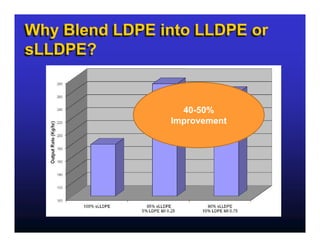
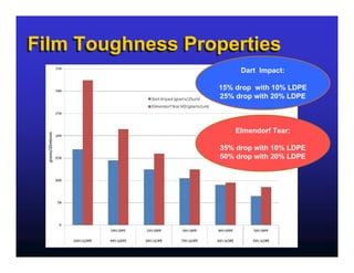
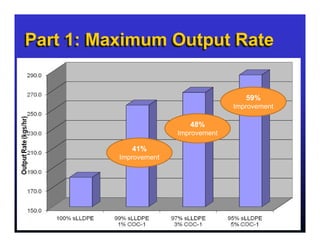
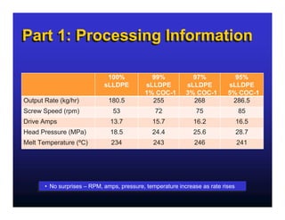
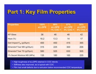
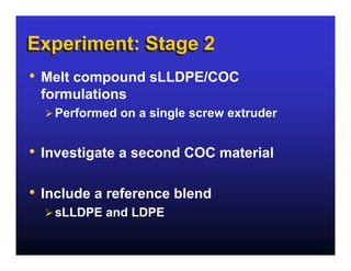
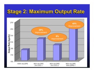
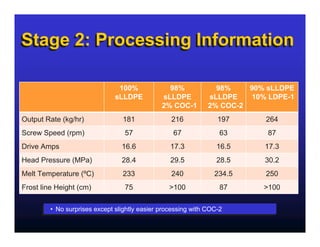
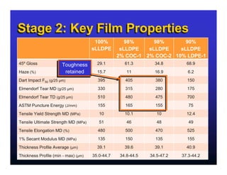
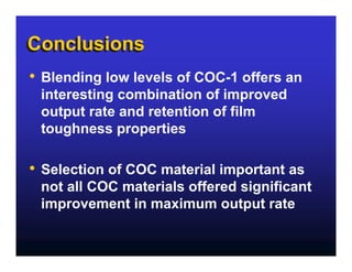
SPE International Polyolefins Conference
                             February 22 - 25, 2009
                                       Houston, TX

   Blending of Cyclic Olefins
       in single site LLDPE
 (sLLDPE) for Improved Bubble
  Stability and Output Rates on
Blown Film Extrusion Processes
      Presented by: Timothy Kneale
Outline
•   Background
•   Idea
•   Materials
•   Experiment - Part 1
•   Experiment - Part 2
•   Conclusions
•   Acknowledgements
Why Blend LDPE into LLDPE or
sLLDPE?
sLLDPE?


                  40-50%
                Improvement
Film Toughness Properties
                       Dart Impact:

                  15% drop with 10% LDPE
                  25% drop with 20% LDPE


                      Elmendorf Tear:

                  35% drop with 10% LDPE
                  50% drop with 20% LDPE
Idea / Concept
•   Cyclic olefin copolymers are utilized in
    polyethylene to enhance thermoforming
    properties

•   Could COCs improve bubble stability and
    maximum output rate?
Materials
  Polyethylene
                                Melt Index      Density        Catalyst
               Grade
                              (dg/min, 190C)    (g/cm3)         Type
sLLDPE   SURPASS® FPs117-C         1.0           0.917          SSC
LDPE-1   NOVAPOL® LF-Y819-A        0.75          0.919              -


 Cyclic Olefin Copolymer
                                                              MFI
                 Grade                Tg, ºC
                                                         (dg/min, 230C)
COC-1        TOPAS® 5013X14               136                  8
COC-2        TOPAS® 9506X5                68                  5.5
Equipment
             Nova Research & Technical Centre, Calgary
            Nova Research & Technical Centre, Calgary
            •• Macro monolayer blown film line
                Macro monolayer blown film line
            •• 89 mm (3.5”) smooth bore extruder, 30:1
                89 mm (3.5”) smooth bore extruder, 30:1
            •• Barrier screw
                Barrier screw
            •• 203 mm (8”) rotating die, 1.27 mm (50 mil) die gap
                203 mm (8”) rotating die, 1.27 mm (50 mil) die gap
                Dual lip air ring plus IBC
            •• Dual lip air ring plus IBC
            •• Adjustable height nip
                Adjustable height nip
Determination of Maximum
Output Rate
• Maximum output rate on blown film equipment
    is often limited by bubble stability
•   As output rate is increased bubble will oscillate
    or move, correlating with poor or reduced film
    quality (i.e. increased gauge variation, layflat
    variation, movement of frostline height)
•   Criteria for determining maximum output rate:
      Stability of bubble (limited oscillations result in little
      or no variation in layflat width)
      Gauge variability (maintained within +/-10% when
      measured around bubble)
Part 1: Blends
• 100% sLLDPE control

• Blends of sLLDPE with:
    1% COC-1
    3% COC-1
    5% COC-1
Part 1: Maximum Output Rate


                                         59%
                                      Improvement

                           48%
                        Improvement

             41%
          Improvement
Part 1: Processing Information

                              100%            99%             97%             95%
                             sLLDPE         sLLDPE          sLLDPE          sLLDPE
                                            1% COC-1        3% COC-1        5% COC-1
Output Rate (kg/hr)           180.5           255             268            286.5
Screw Speed (rpm)               53              72              75                85
Drive Amps                     13.7            15.7            16.2               16.5
Head Pressure (MPa)            18.5            24.4            25.6               28.7
Melt Temperature (ºC)          234             243             246                241


      •• No surprises – RPM, amps, pressure, temperature increase as rate rises
         No surprises – RPM, amps, pressure, temperature increase as rate rises
Part 1: Key Film Properties

Properties                       100%           99%           97%           95%
                                sLLDPE        sLLDPE        sLLDPE        sLLDPE
                                              1% COC-1      3% COC-1      5% COC-1

45º Gloss                          36            46             46            42
Haze (%)                          18.2          13.3            14            17
Dart Impact F50 (g/25µm)           400           450           415           365
Elmendorf Tear MD (g/25µm)         315           225           300           205
Elmendorf Tear TD (g/25µm)         580           525           630           505
1% Secant Modulus MD (MPa)         135           180           185           225


    •• High toughness of sLLDPE retained in COC blends
       High toughness of sLLDPE retained in COC blends
    •• Stiffness also improved, as is typical with COC
       Stiffness also improved, as is typical with COC
    •• Film had small defects due to extrusion below recommended COC temperature
       Film had small defects due to extrusion below recommended COC temperature
Experiment: Stage 2
•   Melt compound sLLDPE/COC
    formulations
      Performed on a single screw extruder


•   Investigate a second COC material

•   Include a reference blend
      sLLDPE and LDPE
Stage 2: Maximum Output Rate

                                         45%
                                      Improvement
             20%
          Improvement
                            8%
                        Improvement
Stage 2: Processing Information

                               100%              98%             98%    90% sLLDPE
                              sLLDPE           sLLDPE          sLLDPE   10% LDPE-1
                                               2% COC-1        2% COC-2
Output Rate (kg/hr)              181              216             197      264
Screw Speed (rpm)                 57               67              63       87
Drive Amps                       16.6             17.3            16.5     17.3
Head Pressure (MPa)              28.4             29.5            28.5     30.2
Melt Temperature (ºC)            233              240            234.5     250
Frost line Height (cm)            75             >100              87      >100


        •• No surprises except slightly easier processing with COC-2
           No surprises except slightly easier processing with COC-2
Stage 2: Key Film Properties
                                      100%          98%      98%       90%
                                     sLLDPE       sLLDPE   sLLDPE    sLLDPE
                                                 2% COC-1 2% COC-2 10% LDPE-1
45º Gloss             Toughness        29.1         61.3        34.8        68.9
                      Toughness
Haze (%)                retained
                       retained        15.7          11         16.9         6.2
Dart Impact F50 (g/25 µm)              395          405         380         150
Elmendorf Tear MD (g/25 µm)            330          315         280         175
Elmendorf Tear TD (g/25 µm)            510          480         475         700
ASTM Puncture Energy (J/mm)            155          165         155          75
Tensile Yield Strength MD (MPa)         10          10.1         10         12.4
Tensile Ultimate Strength MD (MPa)      51           46          48          49
Tensile Elongation MD (%)              480          500         470         525
1% Secant Modulus MD (MPa)             135          150         135         155
Thickness Profile Average (µm)         39.1         39.6        39.1        40.9
Thickness Profile (min - max) (µm)   35.0-44.7    34.8-44.5   34.5-47.2   37.3-44.2
Conclusions
•   Blending low levels of COC-1 offers an
    interesting combination of improved
    output rate and retention of film
    toughness properties

•   Selection of COC material important as
    not all COC materials offered significant
    improvement in maximum output rate
Acknowledgements
•   Nova Chemicals
      Norm Aubee, Hector Larrazabal
      NRTC Lab Team


•   TOPAS Advanced Polymers
      Paul Tatarka

Boost Blown Film Rate

  • 1.
    SPE International PolyolefinsConference February 22 - 25, 2009 Houston, TX Blending of Cyclic Olefins in single site LLDPE (sLLDPE) for Improved Bubble Stability and Output Rates on Blown Film Extrusion Processes Presented by: Timothy Kneale
  • 2.
    Outline • Background • Idea • Materials • Experiment - Part 1 • Experiment - Part 2 • Conclusions • Acknowledgements
  • 3.
    Why Blend LDPEinto LLDPE or Why Blend LDPE into LLDPE or sLLDPE? sLLDPE? 40-50% Improvement
  • 4.
    Film Toughness Properties Dart Impact: 15% drop with 10% LDPE 25% drop with 20% LDPE Elmendorf Tear: 35% drop with 10% LDPE 50% drop with 20% LDPE
  • 5.
    Idea / Concept • Cyclic olefin copolymers are utilized in polyethylene to enhance thermoforming properties • Could COCs improve bubble stability and maximum output rate?
  • 6.
    Materials Polyethylene Melt Index Density Catalyst Grade (dg/min, 190C) (g/cm3) Type sLLDPE SURPASS® FPs117-C 1.0 0.917 SSC LDPE-1 NOVAPOL® LF-Y819-A 0.75 0.919 - Cyclic Olefin Copolymer MFI Grade Tg, ºC (dg/min, 230C) COC-1 TOPAS® 5013X14 136 8 COC-2 TOPAS® 9506X5 68 5.5
  • 7.
    Equipment Nova Research & Technical Centre, Calgary Nova Research & Technical Centre, Calgary •• Macro monolayer blown film line Macro monolayer blown film line •• 89 mm (3.5”) smooth bore extruder, 30:1 89 mm (3.5”) smooth bore extruder, 30:1 •• Barrier screw Barrier screw •• 203 mm (8”) rotating die, 1.27 mm (50 mil) die gap 203 mm (8”) rotating die, 1.27 mm (50 mil) die gap Dual lip air ring plus IBC •• Dual lip air ring plus IBC •• Adjustable height nip Adjustable height nip
  • 8.
    Determination of Maximum OutputRate • Maximum output rate on blown film equipment is often limited by bubble stability • As output rate is increased bubble will oscillate or move, correlating with poor or reduced film quality (i.e. increased gauge variation, layflat variation, movement of frostline height) • Criteria for determining maximum output rate: Stability of bubble (limited oscillations result in little or no variation in layflat width) Gauge variability (maintained within +/-10% when measured around bubble)
  • 9.
    Part 1: Blends •100% sLLDPE control • Blends of sLLDPE with: 1% COC-1 3% COC-1 5% COC-1
  • 10.
    Part 1: MaximumOutput Rate 59% Improvement 48% Improvement 41% Improvement
  • 11.
    Part 1: ProcessingInformation 100% 99% 97% 95% sLLDPE sLLDPE sLLDPE sLLDPE 1% COC-1 3% COC-1 5% COC-1 Output Rate (kg/hr) 180.5 255 268 286.5 Screw Speed (rpm) 53 72 75 85 Drive Amps 13.7 15.7 16.2 16.5 Head Pressure (MPa) 18.5 24.4 25.6 28.7 Melt Temperature (ºC) 234 243 246 241 •• No surprises – RPM, amps, pressure, temperature increase as rate rises No surprises – RPM, amps, pressure, temperature increase as rate rises
  • 12.
    Part 1: KeyFilm Properties Properties 100% 99% 97% 95% sLLDPE sLLDPE sLLDPE sLLDPE 1% COC-1 3% COC-1 5% COC-1 45º Gloss 36 46 46 42 Haze (%) 18.2 13.3 14 17 Dart Impact F50 (g/25µm) 400 450 415 365 Elmendorf Tear MD (g/25µm) 315 225 300 205 Elmendorf Tear TD (g/25µm) 580 525 630 505 1% Secant Modulus MD (MPa) 135 180 185 225 •• High toughness of sLLDPE retained in COC blends High toughness of sLLDPE retained in COC blends •• Stiffness also improved, as is typical with COC Stiffness also improved, as is typical with COC •• Film had small defects due to extrusion below recommended COC temperature Film had small defects due to extrusion below recommended COC temperature
  • 13.
    Experiment: Stage 2 • Melt compound sLLDPE/COC formulations Performed on a single screw extruder • Investigate a second COC material • Include a reference blend sLLDPE and LDPE
  • 14.
    Stage 2: MaximumOutput Rate 45% Improvement 20% Improvement 8% Improvement
  • 15.
    Stage 2: ProcessingInformation 100% 98% 98% 90% sLLDPE sLLDPE sLLDPE sLLDPE 10% LDPE-1 2% COC-1 2% COC-2 Output Rate (kg/hr) 181 216 197 264 Screw Speed (rpm) 57 67 63 87 Drive Amps 16.6 17.3 16.5 17.3 Head Pressure (MPa) 28.4 29.5 28.5 30.2 Melt Temperature (ºC) 233 240 234.5 250 Frost line Height (cm) 75 >100 87 >100 •• No surprises except slightly easier processing with COC-2 No surprises except slightly easier processing with COC-2
  • 16.
    Stage 2: KeyFilm Properties 100% 98% 98% 90% sLLDPE sLLDPE sLLDPE sLLDPE 2% COC-1 2% COC-2 10% LDPE-1 45º Gloss Toughness 29.1 61.3 34.8 68.9 Toughness Haze (%) retained retained 15.7 11 16.9 6.2 Dart Impact F50 (g/25 µm) 395 405 380 150 Elmendorf Tear MD (g/25 µm) 330 315 280 175 Elmendorf Tear TD (g/25 µm) 510 480 475 700 ASTM Puncture Energy (J/mm) 155 165 155 75 Tensile Yield Strength MD (MPa) 10 10.1 10 12.4 Tensile Ultimate Strength MD (MPa) 51 46 48 49 Tensile Elongation MD (%) 480 500 470 525 1% Secant Modulus MD (MPa) 135 150 135 155 Thickness Profile Average (µm) 39.1 39.6 39.1 40.9 Thickness Profile (min - max) (µm) 35.0-44.7 34.8-44.5 34.5-47.2 37.3-44.2
  • 17.
    Conclusions • Blending low levels of COC-1 offers an interesting combination of improved output rate and retention of film toughness properties • Selection of COC material important as not all COC materials offered significant improvement in maximum output rate
  • 18.
    Acknowledgements • Nova Chemicals Norm Aubee, Hector Larrazabal NRTC Lab Team • TOPAS Advanced Polymers Paul Tatarka