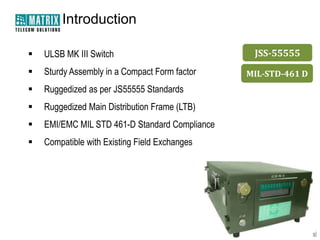
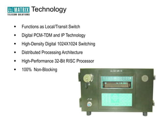
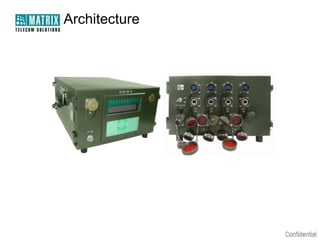
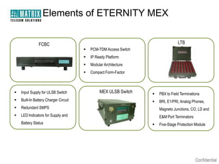
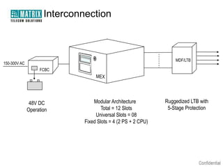
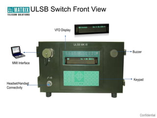
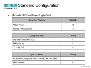
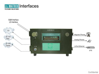
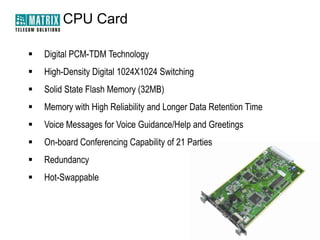
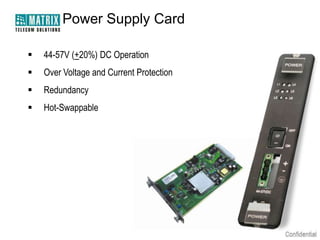
Warm Welcome
ETERNITY MEX
The Military Exchange
(ULSB MK III)
Agenda


Introduction



Technology



Architecture



Functions and Operational Specifications



Management and Maintenance



Key Differentiators
Introduction


ULSB MK III Switch



Sturdy Assembly in a Compact Form factor



Ruggedized as per JS55555 Standards



Ruggedized Main Distribution Frame (LTB)



EMI/EMC MIL STD 461-D Standard Compliance



Compatible with Existing Field Exchanges

JSS-55555
MIL-STD-461 D
Technology


Functions as Local/Transit Switch



Digital PCM-TDM and IP Technology



High-Density Digital 1024X1024 Switching



Distributed Processing Architecture



High-Performance 32-Bit RISC Processor



100% Non-Blocking
Architecture
Elements of ETERNITY MEX
FCBC

LTB


PCM-TDM Access Switch



IP Ready Platform



Modular Architecture



Compact Form-Factor

MEX ULSB Switch



Input Supply for ULSB Switch



Built-In Battery Charger Circuit



Redundant SMPS

Magneto Junctions, CO, LD and



LED Indicators for Supply and

E&M Port Terminators

Battery Status



PBX to Field Terminations



BRI, E1/PRI, Analog Phones,



Five-Stage Protection Module
Interconnection

MDF/LTB

150-300V AC
FCBC

48V DC
Operation

Modular Architecture
Total = 12 Slots
Universal Slots = 08
Fixed Slots = 4 (2 PS + 2 CPU)

Ruggedized LTB with
5-Stage Protection
ULSB Switch Front View
VFD Display

Buzzer
MMI Interface

Headset/Handset
Connectivity

Keypad
ULSB Switch Rear View
E1 over Fiber Optic

4 Data Ports for
DTE/DCE

Fuse
48V DC Supply

128-Pin LTB Connector
FCBC


Redundancy for SMPS



FCBC Input:150-300 VAC Input



Battery Output : 48VDC



FCBC Output: 48VDC to ULSB Power Supply Card



Over Voltage and Reverse Voltage Protection



Micro-Controller Based FCBC

Front

Rear
FCBC LED Indicators

 Status Indication of Power Supply from AC Mains
 Status Indication of Power Feed from Battery
 Battery Output On/Off Indication
 Absence of Battery Indication
 Indication for Over and Under Voltage of Battery
 Indication of Battery in Charging Mode
 Indication of Battery in Float Mode
 Battery Polarity Reversal Indication
Line Termination Box


Military-Grade LTB



Enclosed in Suitable Harness



Five-Stage Protection Module



Integrated Protection Against Lightning/Electrical Surges/Standing

Voltages for Each Port
Standard Configuration


Redundant CPU and Power Supply Cards
Subscriber Stations

Capacity

Analog Phones

24

Magneto Phone Junctions

8

Analog Trunk Ports

Capacity

Two Wire Central Office (CO)

8

E&M (2W/4W)

8

LD ( Loop Dial)

8
Digital Trunk Ports

Capacity

E1 (Software Configurable for CAS, R2MFC, PRI and QSIG)

4

BRI U Interface

8
Interfaces
E&M Interface
LD Interface

CO
Magneto Phones

E1 over
Fiber
E1 over
Copper

Analog Phones

4-Port Ethernet
DTE
CPU Card


Digital PCM-TDM Technology



High-Density Digital 1024X1024 Switching



Solid State Flash Memory (32MB)



Memory with High Reliability and Longer Data Retention Time



Voice Messages for Voice Guidance/Help and Greetings



On-board Conferencing Capability of 21 Parties



Redundancy



Hot-Swappable
Power Supply Card


44-57V (+20%) DC Operation



Over Voltage and Current Protection



Redundancy



Hot-Swappable
COMBO Card


Common Card for Following Ports:
Interface

Ports/Card

Analog Phones

6

Mangeto Phone Junctions

2

E&M Ports

2

Loop Dial (LD) Ports

2

2 Wire Central Office (CO)

2



Automatic Thermal Management on Subscriber and Tie Lines



On-Board Secondary Protection



Hot-Swappable
ISDN BRI Card


8 BRI Ports/Card



BRI (2B + D) U Interface



Connectivity for ISDN Devices via NT1



Hot-Swappable
E1FO Card


E1/PRI Termination Card with 2 PRI Ports/Card



Software Configurable for CAS, R2MFC, PRI and QSIG



Voice and Data Support



Full QSIG Feature Transparency as per ECMA, ETSI & ISO Standards



Copper Interface for E1 Termination



Direct Optical Interface for Monomode Fiber



Fiber Interface up to 20 Km on Monomode OFC



Hot-Swappable
DATA Card


Integrated 4 Ethernet Ports on Single Card



Data Transfer and Control Applications



A Bifurcated E1 Stream can be Mapped to the Any Ethernet Port



Hot-Swappable
Optional Interfaces and Cards


SLT16, and SLT24 Card



VoIP (IP Trunk + IP Extension)



GSM/3G (SIM)



CDMA (SIM)



VMS (Voice Mail Card)



VHF/UHF Radio Interface with PTT
Features and
Operational Specifications
Operator Console


The Operator Console Embeds:


The VFD Display



The Display Menu



The Navigation Keys



The Dial Pad



The Function Keys



Handset and Headset
The VFD Display



4x40 VFD (Vacuum Florescent Display) Display



Called/Calling Number and Name Display



Access Features Like Call Forward, Transfer, Phonebook and Others from the
Menu Displayed on the VFD



View Call Logs, System Activity and Fault Logs



Displays POST (Power-On self-test) and BITE (Built-In Test Equipment) Test Results
The Dial Pad
 The Dial Pad is used for Dialing Internal/External Numbers, Dial Access
Codes and Name Characters Or While Programming the System

 Consists of 12 Standard Dialing Keys
 Numbers from 0-9
 Characters “” and “#” and “A to Z”
Direct Access Function Keys
Key Name

Function

F1 to F5

Call Loop 1 to 5

NAME

Dial By Name

FWD

Call Forward

ACB

Auto Call Back

RDL

Redial

RING

Ringer

CONF

Conference

FREL

Forced Release

ANS

Call Answer

HOLD

Call Hold

XFR

Call Transfer

REL

Call Release
The Handset and Headset
 Ruggedized Handset with MIL Standard Connector
 Headset Connectivity for Hands-Free Operation
 Common Interface is Provided for Headset and Headset, Either of One
Can be Connected at an Instant
Display Menu
Following Features Can be Accessed from the Display Menu:
Alarm

To Set/Cancel Alarms

Call Cost Display

To View Cost of Calls Made

Call Forward

To Set/Cancel Call Forward

Call Logs

To View History of Answered, Missed and Dialed Calls

Contacts

To Call, Add, Edit, Delete Names and Numbers from the Directory

Change User Password

To Alter the Password

Do-Not-Disturb (DND)

To Set (Blocking Incoming Calls)/Cancel DND

Dynamic Lock

To Change Toll Control Level for Making Calls

Keypad Lock

To Lock/Unlock the Keypad

Phone Settings

To Change Settings of Volume, Ringer, Display Menu and Others

User Status

To Set User Status to Present or Absent
Reliability


Continuous Operation on 24 Hour Basis



No Overheating or Breakdowns



Distributed Processing Architecture with Intelligent Local Processing
Units for Each Card



Integrated DSP based SLIC and DAA are used for Analog Subscriber

and Trunk Interfaces


Best-of-Breed Software Protocol Stacks are used for Digital Interfaces



Redundancy for Critical Cards (PSU and CPU)



MTBF better than 5000 Working Hours



MTTR better than 30 Minutes
Ruggedization


Equipped with Necessary Ruggedization for Tactical Military

Environments


Leak Proof Electrical Connectors



Toughened Connectors and LTB



Efficient Thermal Management on Subscriber and Tie Lines



No Moving Parts



Cards are Secured to Slots Avoiding Dislocation During Moves
Transportability


Light-Weight Switch for Easy Transit



Weight of Equipment (Less Accessories) Equals 20 Kgs



Accessories:


Handles on Equipment for Easy Movement



Man-Pack Harness



Transit Case for Easy Transportation
Man-Pack Harness


Man-Pack Harnesses for Easy Carriage During Commutation



Harness for:


ULSB Switch



FCBC



LTB Unit



Laptop



Headset and Handset



LTB, MMI, Power Supply, Earthing, Testing and Other Connecting Cables



Earthing, Tool and Optical Kit



Vehicle Mounting Kit



Testing Telephones
Transit Case


Transit Cases for Easy Movement and Packaging



The Cases Encompasses:


ULSB Switch



FCBC



LTB Unit



Laptop



Headset and Handset



LTB, MMI, Power Supply, Earthing and Other Connecting Cables



Earthing, Tool and Optical Kit



Vehicle Mounting Kit



Testing Telephones
Vehicle Mounting Kit (VMK)

Vehicle Mounting Kit for
FCBC

Vehicle Mounting Kit for
ULSB Switch
Environmental Specifications


Impervious Performance under Varying Climatic Conditions
Parameters

Range
.

.

Operating Temperature

-20 C to + 55 C

Operating Humidity

5-95 % RH, Non-Condensing

Storage Temperature

-40 C to +85 C (-40 F to +185 F)

Storage Humidity

0-95 % RH, Non-Condensing

.

.

.

.
Earthing


Matrix MEX can Work on Field Type of Earthing (up to 5 ohm)



Earthing Points on Main Switch, FCBC and LTB



Earthing Spikes are Provided with Other Accessories (Earthing Rods,
Cables and Braids)

Earthing Rods

Earthing Braid
Camouflage


Color Scheme Inline to Provide Proper Concealment



ULSB Switch, FCBC, LTB, Transit Cases and Harnesses
– “All in Camouflage”
Management and Maintenance
Configuration and Management


Ruggedized MMI/NMS Terminal



Local as well as Remote Management



Configuration through Operator Console



Visual Indications for Health Status of Cards



Remote Configuration via Dial-Up Modem



Web based Graphical User Interface



Access Levels Secured with Passwords
MMI Interface


MIL Standard MMI Interface on the Front Fascia



EMI Protected Cable with a Sealed Connector on One End and Industrial
Connector to for Laptop



Access GUI



Capture and Download Station Message Detail Records (SMDR)



Capture and Download System Activity and Fault Logs.



Download Call Statistics Reports
System Diagnosis


Power on Self Test, On-Line and Off-Line Diagnostics



BITE (Built-in Test Equipment) Testing for Self Diagnostic of Various Ports
Like SLT, Magneto, CO(TWT), E&M and LD



Card Level System Diagnostics through MMI/NMS



Visual/Aural Alarm Indicating Critical Failure
BITE Test



Test Proper Functioning of Various Trunk and Extension Ports:




SLT, Magneto, CO, Loop Dial, E&M and E1

Proper Functioning of a Port is Tested by Looping Back the Port with the Opposite
Gender Port



BITE Results are Recorded in the System Activity Log
System and Traffic Statistics


Per Port/Trunk Occupation Reports with Time and Duration



Built-in SMDR for 12000 Records



System Event and Fault Logs
Maintenance and Repairs


Modular Construction to Facilitate Individual Replacement of Faulty Cards



Comprehensive Literature Conforming to JSS 0251-01 Standards
Key Differentiators
Key Differentiators


A Perfect Blend of Innovation, Intelligence and Integration



Flexible and Scalable Communication Platform



Rich Features and Functions



Flexible Call Management



Easy Installation and Setup



Comprehensive Monitoring and Management Reports
Key Differentiators


Redundancy for Critical Cards



Hot-Swappable Cards



CNR Functionality through E&M ports



Built-in SMDR/CDR of 12,000 Call Records



On-board Conferencing Capability of 21 Parties



On-board Secondary Protection
Key Differentiators


LTB with 5-Stage Protection



Self-Diagnostic Tests



System Fault and Event Logs



Watch Dog Functionality



Minimum Internal Cabling



All Aluminum Enclosure
 Type of Presentation: Product Introduction and Features
 Number of Slides: 51
 Revised On: 29th September, 2011

 Version-Release Number: V1R1

For Further Information Please Contact:
Email ID: pmt@matrixcomsec.com
Mobile: +91 9662544401
Visit us at www.matrixcomsec.com
Thank You
www.MatrixComSec.com

Matrix Telecom Solutions: ETERNITY MEX - The ULSB MK III Switch

  • 1.
  • 2.
    ETERNITY MEX The MilitaryExchange (ULSB MK III)
  • 3.
    Agenda  Introduction  Technology  Architecture  Functions and OperationalSpecifications  Management and Maintenance  Key Differentiators
  • 4.
    Introduction  ULSB MK IIISwitch  Sturdy Assembly in a Compact Form factor  Ruggedized as per JS55555 Standards  Ruggedized Main Distribution Frame (LTB)  EMI/EMC MIL STD 461-D Standard Compliance  Compatible with Existing Field Exchanges JSS-55555 MIL-STD-461 D
  • 5.
    Technology  Functions as Local/TransitSwitch  Digital PCM-TDM and IP Technology  High-Density Digital 1024X1024 Switching  Distributed Processing Architecture  High-Performance 32-Bit RISC Processor  100% Non-Blocking
  • 6.
  • 7.
    Elements of ETERNITYMEX FCBC LTB  PCM-TDM Access Switch  IP Ready Platform  Modular Architecture  Compact Form-Factor MEX ULSB Switch  Input Supply for ULSB Switch  Built-In Battery Charger Circuit  Redundant SMPS Magneto Junctions, CO, LD and  LED Indicators for Supply and E&M Port Terminators Battery Status  PBX to Field Terminations  BRI, E1/PRI, Analog Phones,  Five-Stage Protection Module
  • 8.
    Interconnection MDF/LTB 150-300V AC FCBC 48V DC Operation ModularArchitecture Total = 12 Slots Universal Slots = 08 Fixed Slots = 4 (2 PS + 2 CPU) Ruggedized LTB with 5-Stage Protection
  • 9.
    ULSB Switch FrontView VFD Display Buzzer MMI Interface Headset/Handset Connectivity Keypad
  • 10.
    ULSB Switch RearView E1 over Fiber Optic 4 Data Ports for DTE/DCE Fuse 48V DC Supply 128-Pin LTB Connector
  • 11.
    FCBC  Redundancy for SMPS  FCBCInput:150-300 VAC Input  Battery Output : 48VDC  FCBC Output: 48VDC to ULSB Power Supply Card  Over Voltage and Reverse Voltage Protection  Micro-Controller Based FCBC Front Rear
  • 12.
    FCBC LED Indicators Status Indication of Power Supply from AC Mains  Status Indication of Power Feed from Battery  Battery Output On/Off Indication  Absence of Battery Indication  Indication for Over and Under Voltage of Battery  Indication of Battery in Charging Mode  Indication of Battery in Float Mode  Battery Polarity Reversal Indication
  • 13.
    Line Termination Box  Military-GradeLTB  Enclosed in Suitable Harness  Five-Stage Protection Module  Integrated Protection Against Lightning/Electrical Surges/Standing Voltages for Each Port
  • 14.
    Standard Configuration  Redundant CPUand Power Supply Cards Subscriber Stations Capacity Analog Phones 24 Magneto Phone Junctions 8 Analog Trunk Ports Capacity Two Wire Central Office (CO) 8 E&M (2W/4W) 8 LD ( Loop Dial) 8 Digital Trunk Ports Capacity E1 (Software Configurable for CAS, R2MFC, PRI and QSIG) 4 BRI U Interface 8
  • 15.
    Interfaces E&M Interface LD Interface CO MagnetoPhones E1 over Fiber E1 over Copper Analog Phones 4-Port Ethernet DTE
  • 16.
    CPU Card  Digital PCM-TDMTechnology  High-Density Digital 1024X1024 Switching  Solid State Flash Memory (32MB)  Memory with High Reliability and Longer Data Retention Time  Voice Messages for Voice Guidance/Help and Greetings  On-board Conferencing Capability of 21 Parties  Redundancy  Hot-Swappable
  • 17.
    Power Supply Card  44-57V(+20%) DC Operation  Over Voltage and Current Protection  Redundancy  Hot-Swappable
  • 18.
    COMBO Card  Common Cardfor Following Ports: Interface Ports/Card Analog Phones 6 Mangeto Phone Junctions 2 E&M Ports 2 Loop Dial (LD) Ports 2 2 Wire Central Office (CO) 2  Automatic Thermal Management on Subscriber and Tie Lines  On-Board Secondary Protection  Hot-Swappable
  • 19.
    ISDN BRI Card  8BRI Ports/Card  BRI (2B + D) U Interface  Connectivity for ISDN Devices via NT1  Hot-Swappable
  • 20.
    E1FO Card  E1/PRI TerminationCard with 2 PRI Ports/Card  Software Configurable for CAS, R2MFC, PRI and QSIG  Voice and Data Support  Full QSIG Feature Transparency as per ECMA, ETSI & ISO Standards  Copper Interface for E1 Termination  Direct Optical Interface for Monomode Fiber  Fiber Interface up to 20 Km on Monomode OFC  Hot-Swappable
  • 21.
    DATA Card  Integrated 4Ethernet Ports on Single Card  Data Transfer and Control Applications  A Bifurcated E1 Stream can be Mapped to the Any Ethernet Port  Hot-Swappable
  • 22.
    Optional Interfaces andCards  SLT16, and SLT24 Card  VoIP (IP Trunk + IP Extension)  GSM/3G (SIM)  CDMA (SIM)  VMS (Voice Mail Card)  VHF/UHF Radio Interface with PTT
  • 23.
  • 24.
    Operator Console  The OperatorConsole Embeds:  The VFD Display  The Display Menu  The Navigation Keys  The Dial Pad  The Function Keys  Handset and Headset
  • 25.
    The VFD Display  4x40VFD (Vacuum Florescent Display) Display  Called/Calling Number and Name Display  Access Features Like Call Forward, Transfer, Phonebook and Others from the Menu Displayed on the VFD  View Call Logs, System Activity and Fault Logs  Displays POST (Power-On self-test) and BITE (Built-In Test Equipment) Test Results
  • 26.
    The Dial Pad The Dial Pad is used for Dialing Internal/External Numbers, Dial Access Codes and Name Characters Or While Programming the System  Consists of 12 Standard Dialing Keys  Numbers from 0-9  Characters “” and “#” and “A to Z”
  • 27.
    Direct Access FunctionKeys Key Name Function F1 to F5 Call Loop 1 to 5 NAME Dial By Name FWD Call Forward ACB Auto Call Back RDL Redial RING Ringer CONF Conference FREL Forced Release ANS Call Answer HOLD Call Hold XFR Call Transfer REL Call Release
  • 28.
    The Handset andHeadset  Ruggedized Handset with MIL Standard Connector  Headset Connectivity for Hands-Free Operation  Common Interface is Provided for Headset and Headset, Either of One Can be Connected at an Instant
  • 29.
    Display Menu Following FeaturesCan be Accessed from the Display Menu: Alarm To Set/Cancel Alarms Call Cost Display To View Cost of Calls Made Call Forward To Set/Cancel Call Forward Call Logs To View History of Answered, Missed and Dialed Calls Contacts To Call, Add, Edit, Delete Names and Numbers from the Directory Change User Password To Alter the Password Do-Not-Disturb (DND) To Set (Blocking Incoming Calls)/Cancel DND Dynamic Lock To Change Toll Control Level for Making Calls Keypad Lock To Lock/Unlock the Keypad Phone Settings To Change Settings of Volume, Ringer, Display Menu and Others User Status To Set User Status to Present or Absent
  • 30.
    Reliability  Continuous Operation on24 Hour Basis  No Overheating or Breakdowns  Distributed Processing Architecture with Intelligent Local Processing Units for Each Card  Integrated DSP based SLIC and DAA are used for Analog Subscriber and Trunk Interfaces  Best-of-Breed Software Protocol Stacks are used for Digital Interfaces  Redundancy for Critical Cards (PSU and CPU)  MTBF better than 5000 Working Hours  MTTR better than 30 Minutes
  • 31.
    Ruggedization  Equipped with NecessaryRuggedization for Tactical Military Environments  Leak Proof Electrical Connectors  Toughened Connectors and LTB  Efficient Thermal Management on Subscriber and Tie Lines  No Moving Parts  Cards are Secured to Slots Avoiding Dislocation During Moves
  • 32.
    Transportability  Light-Weight Switch forEasy Transit  Weight of Equipment (Less Accessories) Equals 20 Kgs  Accessories:  Handles on Equipment for Easy Movement  Man-Pack Harness  Transit Case for Easy Transportation
  • 33.
    Man-Pack Harness  Man-Pack Harnessesfor Easy Carriage During Commutation  Harness for:  ULSB Switch  FCBC  LTB Unit  Laptop  Headset and Handset  LTB, MMI, Power Supply, Earthing, Testing and Other Connecting Cables  Earthing, Tool and Optical Kit  Vehicle Mounting Kit  Testing Telephones
  • 34.
    Transit Case  Transit Casesfor Easy Movement and Packaging  The Cases Encompasses:  ULSB Switch  FCBC  LTB Unit  Laptop  Headset and Handset  LTB, MMI, Power Supply, Earthing and Other Connecting Cables  Earthing, Tool and Optical Kit  Vehicle Mounting Kit  Testing Telephones
  • 35.
    Vehicle Mounting Kit(VMK) Vehicle Mounting Kit for FCBC Vehicle Mounting Kit for ULSB Switch
  • 36.
    Environmental Specifications  Impervious Performanceunder Varying Climatic Conditions Parameters Range . . Operating Temperature -20 C to + 55 C Operating Humidity 5-95 % RH, Non-Condensing Storage Temperature -40 C to +85 C (-40 F to +185 F) Storage Humidity 0-95 % RH, Non-Condensing . . . .
  • 37.
    Earthing  Matrix MEX canWork on Field Type of Earthing (up to 5 ohm)  Earthing Points on Main Switch, FCBC and LTB  Earthing Spikes are Provided with Other Accessories (Earthing Rods, Cables and Braids) Earthing Rods Earthing Braid
  • 38.
    Camouflage  Color Scheme Inlineto Provide Proper Concealment  ULSB Switch, FCBC, LTB, Transit Cases and Harnesses – “All in Camouflage”
  • 39.
  • 40.
    Configuration and Management  RuggedizedMMI/NMS Terminal  Local as well as Remote Management  Configuration through Operator Console  Visual Indications for Health Status of Cards  Remote Configuration via Dial-Up Modem  Web based Graphical User Interface  Access Levels Secured with Passwords
  • 41.
    MMI Interface  MIL StandardMMI Interface on the Front Fascia  EMI Protected Cable with a Sealed Connector on One End and Industrial Connector to for Laptop  Access GUI  Capture and Download Station Message Detail Records (SMDR)  Capture and Download System Activity and Fault Logs.  Download Call Statistics Reports
  • 42.
    System Diagnosis  Power onSelf Test, On-Line and Off-Line Diagnostics  BITE (Built-in Test Equipment) Testing for Self Diagnostic of Various Ports Like SLT, Magneto, CO(TWT), E&M and LD  Card Level System Diagnostics through MMI/NMS  Visual/Aural Alarm Indicating Critical Failure
  • 43.
    BITE Test  Test ProperFunctioning of Various Trunk and Extension Ports:   SLT, Magneto, CO, Loop Dial, E&M and E1 Proper Functioning of a Port is Tested by Looping Back the Port with the Opposite Gender Port  BITE Results are Recorded in the System Activity Log
  • 44.
    System and TrafficStatistics  Per Port/Trunk Occupation Reports with Time and Duration  Built-in SMDR for 12000 Records  System Event and Fault Logs
  • 45.
    Maintenance and Repairs  ModularConstruction to Facilitate Individual Replacement of Faulty Cards  Comprehensive Literature Conforming to JSS 0251-01 Standards
  • 46.
  • 47.
    Key Differentiators  A PerfectBlend of Innovation, Intelligence and Integration  Flexible and Scalable Communication Platform  Rich Features and Functions  Flexible Call Management  Easy Installation and Setup  Comprehensive Monitoring and Management Reports
  • 48.
    Key Differentiators  Redundancy forCritical Cards  Hot-Swappable Cards  CNR Functionality through E&M ports  Built-in SMDR/CDR of 12,000 Call Records  On-board Conferencing Capability of 21 Parties  On-board Secondary Protection
  • 49.
    Key Differentiators  LTB with5-Stage Protection  Self-Diagnostic Tests  System Fault and Event Logs  Watch Dog Functionality  Minimum Internal Cabling  All Aluminum Enclosure
  • 50.
     Type ofPresentation: Product Introduction and Features  Number of Slides: 51  Revised On: 29th September, 2011  Version-Release Number: V1R1 For Further Information Please Contact: Email ID: pmt@matrixcomsec.com Mobile: +91 9662544401 Visit us at www.matrixcomsec.com
  • 51.