Download as PDF, PPTX

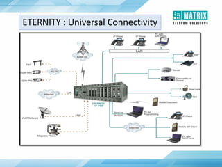
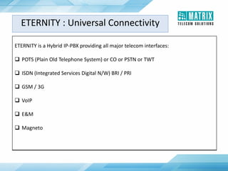
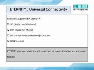
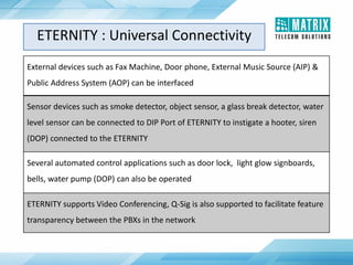
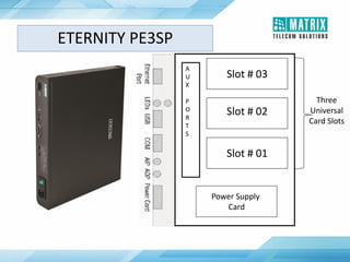
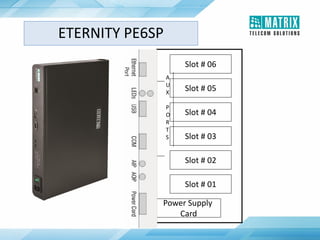
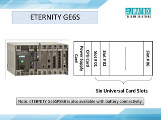
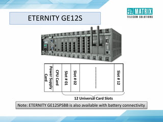
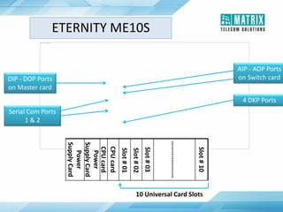
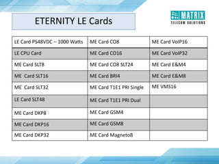
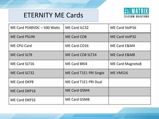
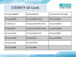
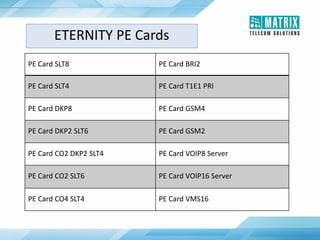
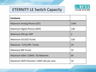
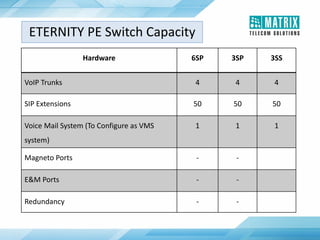
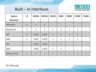
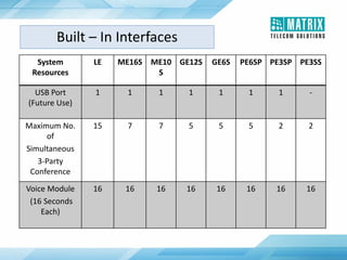
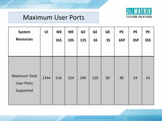
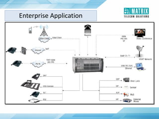
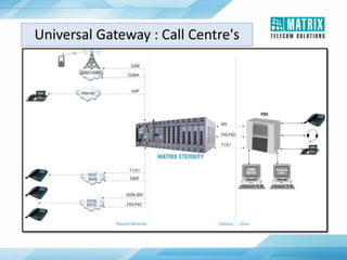

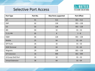


1. The document provides an overview of the Matrix ETERNITY integrated enterprise voice switch, which can support up to 1,344 user ports and provides interfaces for POTS, ISDN, GSM, VoIP, and other systems. 2. ETERNITY supports a variety of extension types including SLT, DKP, SIP, and ISDN terminals. It also interfaces with external devices like fax machines, door phones, and public address systems. 3. ETERNITY is available in different configurations including the LE, ME, GE, and PE models, which provide different capacities for user ports, trunks, and features. The LE can support the most users and trunks while the PE


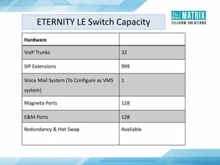
![Getting Started with Apache Spark: Big Data Made Simple [Free Meetup]](https://cdn.slidesharecdn.com/ss_thumbnails/apachesparkgettingstarted-260203175547-8361bcc3-thumbnail.jpg?width=640&height=640&fit=bounds)


