The document provides an overview of SCADA (Supervisory Control and Data Acquisition) systems used in power system management. It discusses:
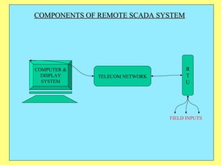
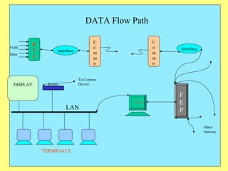
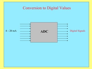
1) SCADA allows remote monitoring and control of equipment by collecting data from devices in the field and presenting it for user-friendly monitoring and analysis.
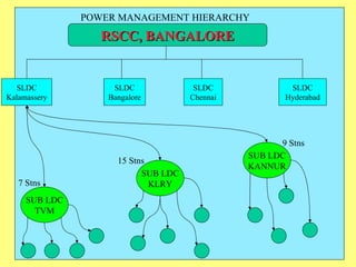
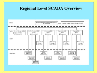
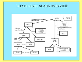
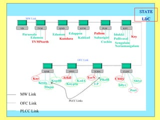
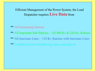
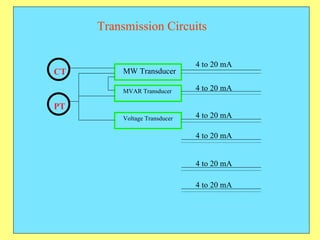
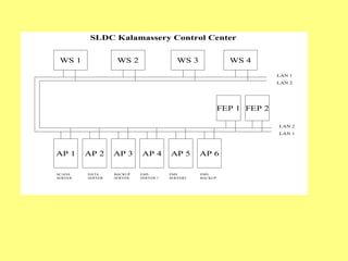
2) In power systems, SCADA is used to monitor generation stations, substations, transmission lines to efficiently manage the system.
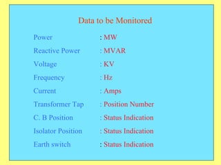
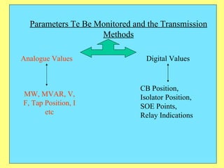
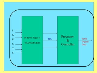
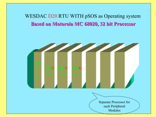
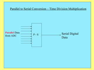
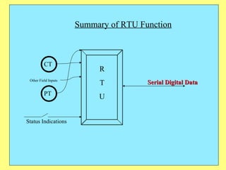
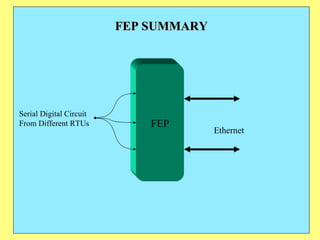
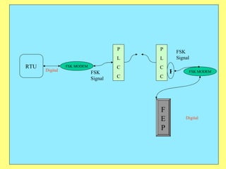
3) Key components include RTUs (Remote Terminal Units) that interface with field devices to collect data, communication networks to transmit data to control centers, and HMI software for operators.