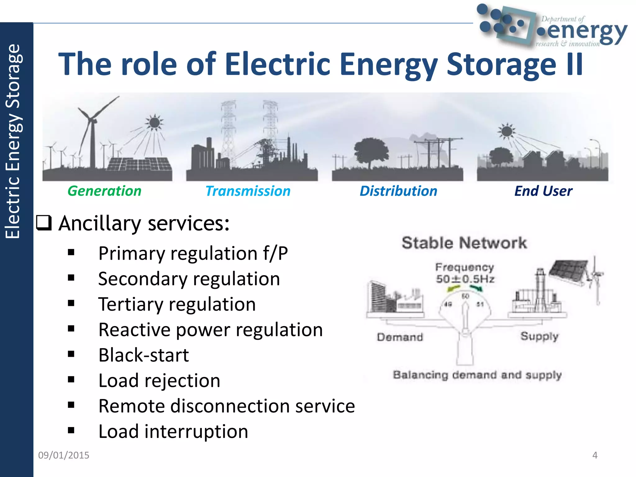
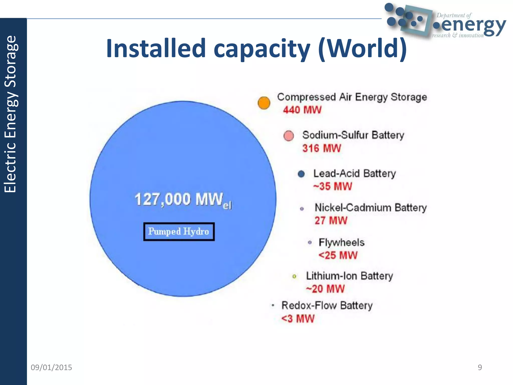
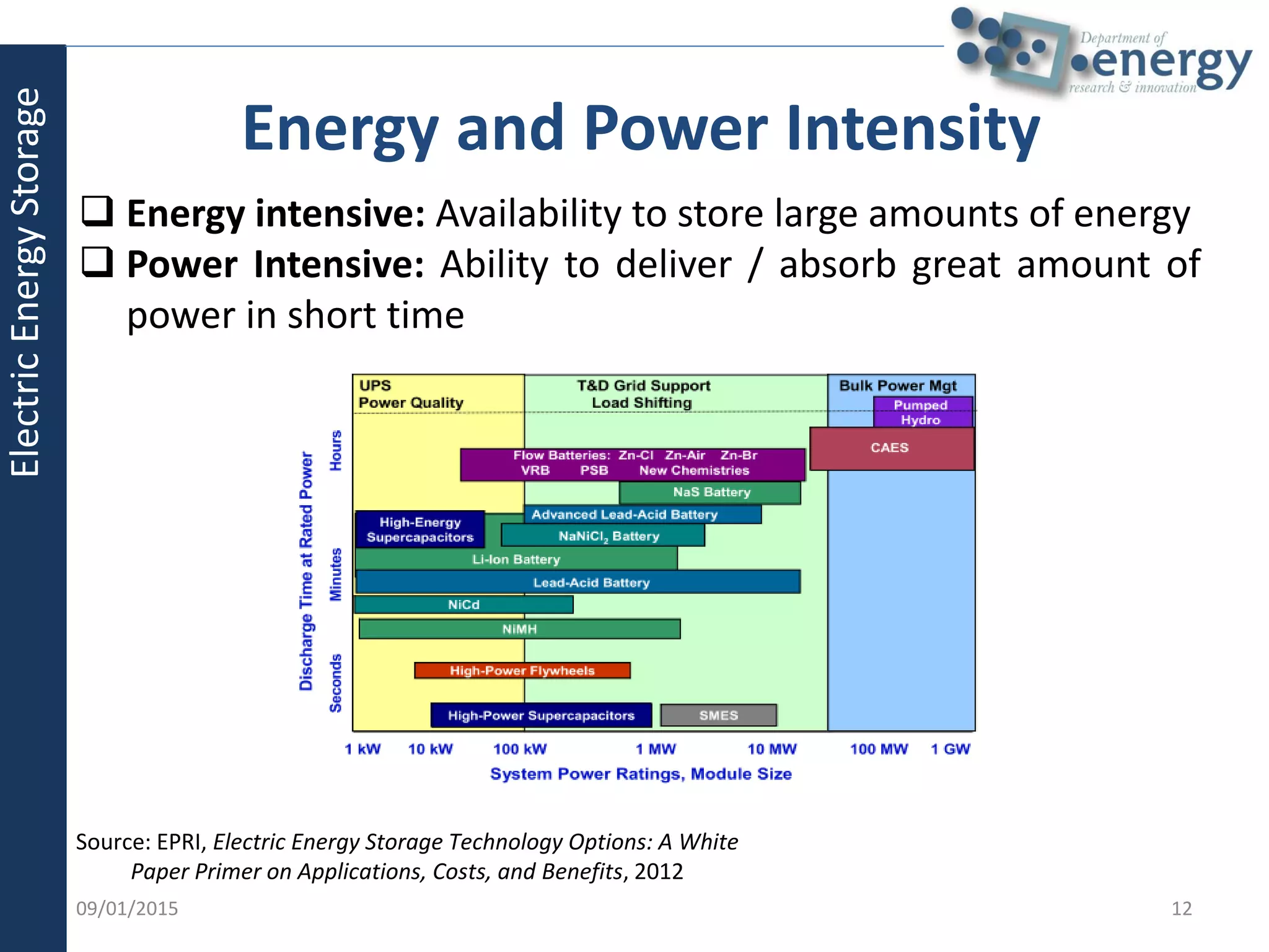
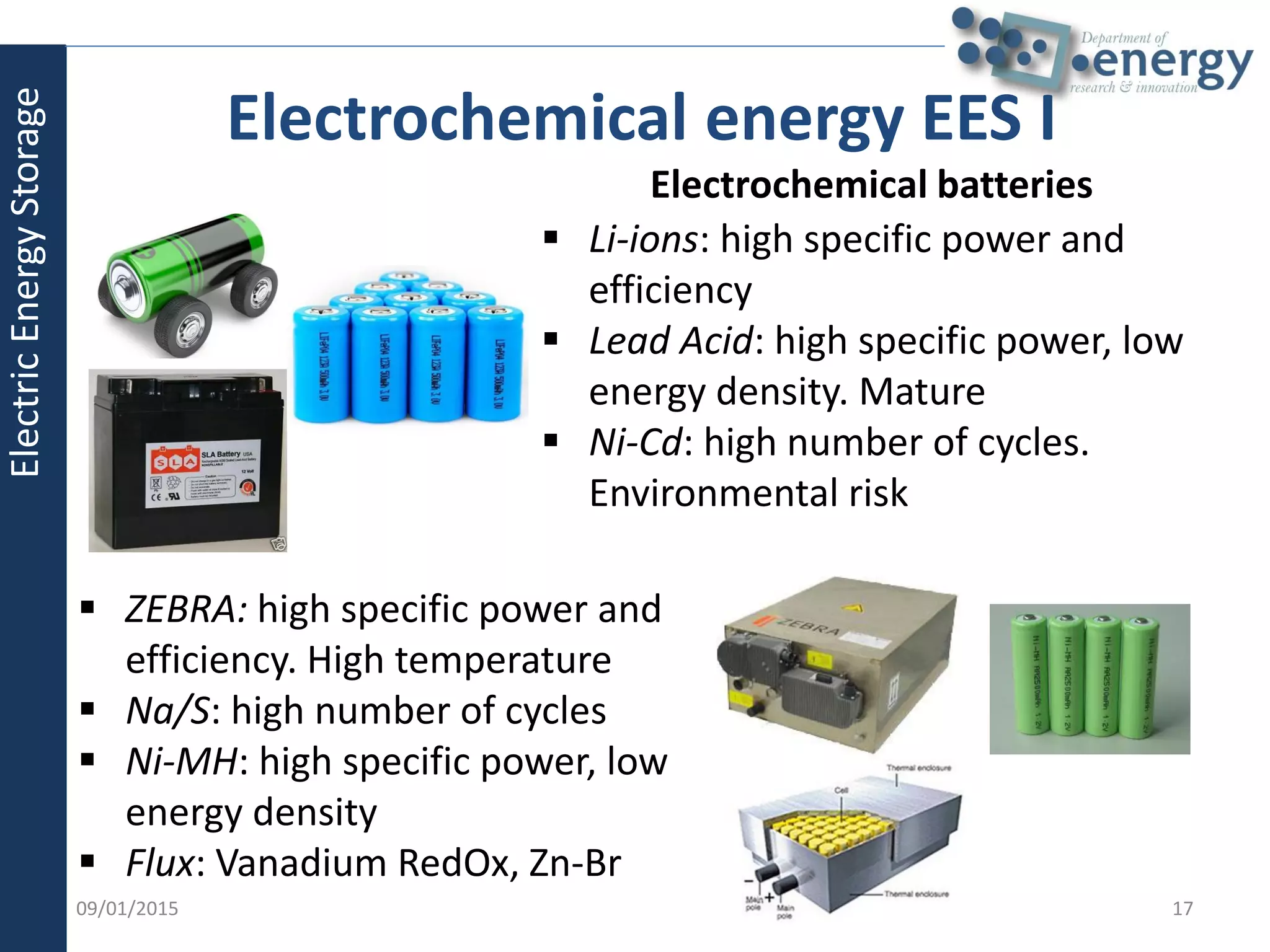
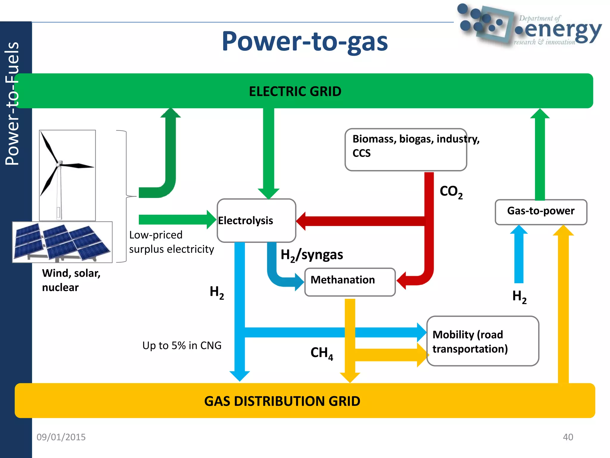
Energy storage in urban
multi-energy systems
Prof. Marco Carlo Masoero
ICARB Workshop: Energy Storage for the Built Environment
Edinburgh, 21st October 2014
Outline of the presentation
 Electrical Energy Storage (EES)
 The role of EES
 The technical parameters
 Electric Energy Storage systems typology
 Thermal Energy Storage (TES)
 Purpose of TES in Energy Plants
 Technologies
 Short-term (daily) vs Long-term (seasonal) storage
 Applications: District Heating and Cooling
 Power-to-Fuels
 Conclusions
209/01/2015
Energystorageinurbanmulti-energysystems
The role of Electric Energy Storage I
3
 Distributed generation
development by renewables
 More efficient use of HV and MV
power grids
 Smart Grid in support to Local
Energy Communities
 Higher flexibility to rapidly respond
to variable load demand
09/01/2015
Generation Transmission Distribution End User
ElectricEnergyStorage
09/01/2015
 Ancillary services:
 Primary regulation f/P
 Secondary regulation
 Tertiary regulation
 Reactive power regulation
 Black-start
 Load rejection
 Remote disconnection service
 Load interruption
4
The role of Electric Energy Storage II
Generation Transmission Distribution End User
ElectricEnergyStorage
09/01/2015 5
EES could represent a feasible solution to dealing
with several aspects:
 Secondary and tertiary regulation
 Over voltage
 Reverse power flows
 Resolution of congestions storage of energy in
excess at peak-hours
The role of Electric Energy Storage III
ElectricEnergyStorage
09/01/2015 6
EES could represent a feasible solution to dealing
with several aspects:
 Line capacity investment deferral: EES discharges at
peak times and charges at off-peak times
 Peak shaving long discharge/charge times
 Power quality short discharge/charge times
 Reduction of the resistive line losses
 Provision of ancillary services:
 balancing energy
 Rotary reserve
 Substitutive reserve
 frequency regulation
• in normal power grid condition
• in islanding working mode
The role of Electric Energy Storage IV
ElectricEnergyStorage
09/01/2015 7
EES could represent a feasible solution to dealing
with several aspects:
 control system and power quality improvement
• Dip voltage and over/under-voltage
• Frequency variations
• Low power factor
• Harmonic distortion
 support service to voltage control
• instead of capacitor banks, EES can compensate for
voltage drop
 provision of black-start services
• overall blackout
The role of Electric Energy Storage V
ElectricEnergyStorage
09/01/2015 8
Source: Eurelectric, Decentralised storage: impact on future distribution grids, 2012
The role of Electric Energy Storage VI
ElectricEnergyStorage
Installed capacity (World)
909/01/2015
ElectricEnergyStorage
09/01/2015 10
EES systems are defined by the following technical
parameters:
• Specific energy (kWh/kg) or energy density (kWh/m3)
• Specific power (kW/kg) or power density (kW/m3)
• Efficiency
• Number of cycles
• Useful life
• Charge/discharge times (h)
• Ramp rate (s)
• Specific costs (€/kWh or €/kW)
• Maturity
The technical parameters I
ElectricEnergyStorage
09/01/2015 11
Mainly the electrochemical EES are also defined by
the following parameters:
• Memory effect
• Charge/discharge velocity
• Depth of discharge
• Self discharge
The technical parameters II
ElectricEnergyStorage
09/01/2015 12
 Energy intensive: Availability to store large amounts of energy
 Power Intensive: Ability to deliver / absorb great amount of
power in short time
Source: EPRI, Electric Energy Storage Technology Options: A White
Paper Primer on Applications, Costs, and Benefits, 2012
Energy and Power Intensity
ElectricEnergyStorage
09/01/2015 13
• Mechanical energy:
• Pumped Hydroelectric Storage (PHS)
• Compressed Air Energy Storage (CAES)
• Flywheels
• Electromagnetic and electrostatic energy:
• Electric Double Layer Capacitors - EDLC
• Superconducting Magnetic Energy Storage – SMES
• Chemical energy (hydrogen vector):
• Compression
• Liquefaction
• Chemi-sorption
• Physi-sorption
• Thermal energy:
• Molten salt
• Liquefied Air Energy Storage (LAES)
• Phase Change Materials
Electric Energy Storage systems typology
ElectricEnergyStorage
 Storage in potential energy
 convenience:
𝑃 𝑔𝑒𝑛
𝑃 𝑝𝑢𝑚𝑝
≥ 1.4
 More than 99% of EES
 Difficulty of installation
 Storage in compressed air
 Integration with thermal power
plants
 Difficulty of installation
14
PHS
CAES
09/01/2015
Mechanical energy EES I
ElectricEnergyStorage
 Storage in kinetic energy
 Angular speed 60.000-100.000 rpm
 High energy density
 Rapid ramp rate
 High efficiency (90-95%)
 High self-discharge
15
Flywheels
09/01/2015
Mechanical energy EES II
Chemical energy (H2 storage)
 Compressed gas: 200-700 bar
 Liquid H2: -253 °C
 Chemi-sorption: Metal hydrides
 Physi-sorption
 Power to Gas: EC + H2 + FC
ElectricEnergyStorage
 Storage in electric field
 Specific energy: 1 ÷ 5 Wh/kg
 Specific power: 100 ÷ 2.000 W/kg
 High number of charge/discharge
cycles
 Storage in magnetic field
 Superconductors between 4÷100 K
 Rapid ramp rate (20 ms)
 High specific power
 High efficiency (>97%)
16
EDLC
SMES
09/01/2015
Electric energy EES I
ElectricEnergyStorage
 Li-ions: high specific power and
efficiency
 Lead Acid: high specific power, low
energy density. Mature
 Ni-Cd: high number of cycles.
Environmental risk
 ZEBRA: high specific power and
efficiency. High temperature
 Na/S: high number of cycles
 Ni-MH: high specific power, low
energy density
 Flux: Vanadium RedOx, Zn-Br
17
Electrochemical batteries
09/01/2015
Electrochemical energy EES I
ElectricEnergyStorage
Purpose of Thermal Energy Storage in
Energy Plants
The use of thermal storage systems in energy plants can have multiple
purposes:
1. Increase the stability in short term operation of the plants (e.g. load
variation in heat pump systems)
2. Reduce the use auxiliary boilers (e.g. in district heating)
3. Shift the heat production through CHP to periods where the electricity
production is more convenient (in the case of backpressure plants or
internal combustion engines) or less convenient (in the case of
extraction plants)
4. Increase the use of renewable primary resources (e.g. solar thermal
systems)
All these have in common the decoupling between heat generation and
utilization.
ThermalEnergyStorage
09/01/2015 18
09/01/2015 19
Technologies
 Water Tanks
 Phase Change Materials
 TABS
 Other (Ice Storage, Pebble Systems,…)
ThermalEnergyStorage
09/01/2015 20
Technologies: Water Tanks
DHW systems Solar Heaters
Daily Storage Systems
ThermalEnergyStorage
09/01/2015 21
Technologies: Water Tanks
Seasonal Storage Systems
ThermalEnergyStorage
09/01/2015 22
Technologies: Embedded Systems
In Thermally Activated Building Systems (TABS) the
thermal capacity of the building is enhanced by the
installation of water pipes within the slabs.
ThermalEnergyStorage
09/01/2015 23
Technologies: Embedded Systems
Phase Change Materials (PCM) can be installed within
structural elements of buildings (typically walls).
Their fusion temperature being around 25°C, their phase
(liquid/solid) changes in a temperature range that is practical
for normal building uses and allows to store/release thermal
energy
ThermalEnergyStorage
09/01/2015 24
District Heating (DH) Networks
 Total Heat Load results from the aggregation of
multiple users
 Need of adapting the heat demand side with the
heat supply side along the day
 Need of operation optimization for different
generation units (e.g. CHP, boilers, heat pumps,
solar collectors)
ThermalEnergyStorage
09/01/2015 25
The role of Thermal Storage:
Decoupling Supply and Demand
Supply Side Demand Side
DH systems have to match the user demand, as a result it is
difficult to optimize CHP size and operation
ThermalEnergyStorage
Current District Heating Network in Turin
As of 31-12-2012:
• largest DH system in Italy
• 53,4 Mm3 supplied buildings
(88 Mm3 in future planning)
• 1.89 TWh heat supplied
• 467 km grid length
• 1.77 GW peak heat
generation
• 1.14 GW of power (CHP)
2609/01/2015
ThermalEnergyStorage
Current District Heating Network in Turin
2709/01/2015
ThermalEnergyStorage
Current + Forecasted DH Network in Turin
09/01/2015 28
ThermalEnergyStorage
09/01/2015 29
The role of Thermal Storage:
Turin DH daily profiles
January
April
July
Daily peaks
ThermalEnergyStorage
09/01/2015
The role of Thermal Storage:
Decoupling Supply and Demand
Turin Politecnico:
Re-Heating and Pumping
Plant with 2.500 m3 storage
North Turin:
Combined Cycle
Cogeneration Plant
with 5000 m3 storage
ThermalEnergyStorage
09/01/2015 31
Heat storage systems behaviour
Storage
Unload
Storage
Load
Heat storage systems
CHP units
Boilers
DH system of Turin
ThermalEnergyStorage
09/01/2015 32
Heat storage systems behaviour
Heat Storage SystemsCHP UnitsBoilers
The heat storage
allows to increase
the utilization factor
of CHP units
DH system of Turin
ThermalEnergyStorage
09/01/2015 33
Biomass DH System Configurations
CHPBoilers +Boilers only
Heat storage
systems
+
CHP
Boilers
+
Hours
HeatLoad
Hours
HeatLoad
Hours
HeatLoad
ThermalEnergyStorage
09/01/2015 34
Biomass DH System Simulation
The heat storage helps to increase the overall efficiency of the system
ThermalEnergyStorage
09/01/2015 35
Biomass DH System Simulation
• The heat storage systems move and lower the optimum pay back time.
• The incentives change the convenience of installing heat storage systems.
Best PBT
ThermalEnergyStorage
District cooling - Gotehnburg
ThermalEnergyStorage
09/01/2015 36
District cooling- Paris Centre
ThermalEnergyStorage
09/01/2015 37
Water cooled Air cooled Total energy storage: 140 MWh
Outine: Power-to-Fuels
09/01/2015 38
ENERGY CONTEXT: THE NEEDS:
1. Large size storage of RES: storage in forms of chemicals
2. Chemicals that can have interest for the energy sector: existing distribution
and utilization infrastructure; several final users (e.g. stationary systems,
automotive, etc.)
3. Chemicals as CO2 sink
A POSSIBLE SOLUTION: GREEN FUELS
One option for fast and sustainable storage is the production of gaseous fuels to
be fed in the distribution grid: those fuels could be produced by means of
electrolysis processes and thus converted into synthetic methane to be fed into
the existing distribution infrastructure.
PROS
1. conversion of relevant amount of renewable sources from “flow” to “stock”
2. chemical fixing of carbon recycled from CO2
3. easy utilization of synthetic methane into existing energy infrastructure
(distribution and final uses)
Power-to-Fuels
Integration of Electric and Gas Networks
09/01/2015 39
Power-to-Fuels
GAS DISTRIBUTION GRID
ELECTRIC GRID
Electrolysis
Low-priced
surplus electricity
H2
Methanation
CH4
CO2
Biomass, biogas, industry,
CCS
Up to 5% in CNG
Mobility (road
transportation)
Gas-to-power
Power-to-gas
H2
Wind, solar,
nuclear
H2/syngas
09/01/2015 40
Power-to-Fuels
09/01/2015 41
Conclusions
 Energy storage is a key issue in any multi-energy
system applied at the urban scale
 Integration of distributed generation should
compete with quality standard warranty
 The role played by EES will be fundamental to shift
towards a smart grid concept
 TES is essential for an efficient integration of
thermal energy production and distribution, using
both fossil and renewable sources
 The choice to install a certain typology of storage
system depends on the application desired
Conclusions
09/01/2015 42
Thank you for your
attention!
marco.masoero@polito.it

Energy storage in urban multi-energy systems | Marco Carlo Masoero

  • 1.
    Energy storage inurban multi-energy systems Prof. Marco Carlo Masoero ICARB Workshop: Energy Storage for the Built Environment Edinburgh, 21st October 2014
  • 2.
    Outline of thepresentation  Electrical Energy Storage (EES)  The role of EES  The technical parameters  Electric Energy Storage systems typology  Thermal Energy Storage (TES)  Purpose of TES in Energy Plants  Technologies  Short-term (daily) vs Long-term (seasonal) storage  Applications: District Heating and Cooling  Power-to-Fuels  Conclusions 209/01/2015 Energystorageinurbanmulti-energysystems
  • 3.
    The role ofElectric Energy Storage I 3  Distributed generation development by renewables  More efficient use of HV and MV power grids  Smart Grid in support to Local Energy Communities  Higher flexibility to rapidly respond to variable load demand 09/01/2015 Generation Transmission Distribution End User ElectricEnergyStorage
  • 4.
    09/01/2015  Ancillary services: Primary regulation f/P  Secondary regulation  Tertiary regulation  Reactive power regulation  Black-start  Load rejection  Remote disconnection service  Load interruption 4 The role of Electric Energy Storage II Generation Transmission Distribution End User ElectricEnergyStorage
  • 5.
    09/01/2015 5 EES couldrepresent a feasible solution to dealing with several aspects:  Secondary and tertiary regulation  Over voltage  Reverse power flows  Resolution of congestions storage of energy in excess at peak-hours The role of Electric Energy Storage III ElectricEnergyStorage
  • 6.
    09/01/2015 6 EES couldrepresent a feasible solution to dealing with several aspects:  Line capacity investment deferral: EES discharges at peak times and charges at off-peak times  Peak shaving long discharge/charge times  Power quality short discharge/charge times  Reduction of the resistive line losses  Provision of ancillary services:  balancing energy  Rotary reserve  Substitutive reserve  frequency regulation • in normal power grid condition • in islanding working mode The role of Electric Energy Storage IV ElectricEnergyStorage
  • 7.
    09/01/2015 7 EES couldrepresent a feasible solution to dealing with several aspects:  control system and power quality improvement • Dip voltage and over/under-voltage • Frequency variations • Low power factor • Harmonic distortion  support service to voltage control • instead of capacitor banks, EES can compensate for voltage drop  provision of black-start services • overall blackout The role of Electric Energy Storage V ElectricEnergyStorage
  • 8.
    09/01/2015 8 Source: Eurelectric,Decentralised storage: impact on future distribution grids, 2012 The role of Electric Energy Storage VI ElectricEnergyStorage
  • 9.
  • 10.
    09/01/2015 10 EES systemsare defined by the following technical parameters: • Specific energy (kWh/kg) or energy density (kWh/m3) • Specific power (kW/kg) or power density (kW/m3) • Efficiency • Number of cycles • Useful life • Charge/discharge times (h) • Ramp rate (s) • Specific costs (€/kWh or €/kW) • Maturity The technical parameters I ElectricEnergyStorage
  • 11.
    09/01/2015 11 Mainly theelectrochemical EES are also defined by the following parameters: • Memory effect • Charge/discharge velocity • Depth of discharge • Self discharge The technical parameters II ElectricEnergyStorage
  • 12.
    09/01/2015 12  Energyintensive: Availability to store large amounts of energy  Power Intensive: Ability to deliver / absorb great amount of power in short time Source: EPRI, Electric Energy Storage Technology Options: A White Paper Primer on Applications, Costs, and Benefits, 2012 Energy and Power Intensity ElectricEnergyStorage
  • 13.
    09/01/2015 13 • Mechanicalenergy: • Pumped Hydroelectric Storage (PHS) • Compressed Air Energy Storage (CAES) • Flywheels • Electromagnetic and electrostatic energy: • Electric Double Layer Capacitors - EDLC • Superconducting Magnetic Energy Storage – SMES • Chemical energy (hydrogen vector): • Compression • Liquefaction • Chemi-sorption • Physi-sorption • Thermal energy: • Molten salt • Liquefied Air Energy Storage (LAES) • Phase Change Materials Electric Energy Storage systems typology ElectricEnergyStorage
  • 14.
     Storage inpotential energy  convenience: 𝑃 𝑔𝑒𝑛 𝑃 𝑝𝑢𝑚𝑝 ≥ 1.4  More than 99% of EES  Difficulty of installation  Storage in compressed air  Integration with thermal power plants  Difficulty of installation 14 PHS CAES 09/01/2015 Mechanical energy EES I ElectricEnergyStorage
  • 15.
     Storage inkinetic energy  Angular speed 60.000-100.000 rpm  High energy density  Rapid ramp rate  High efficiency (90-95%)  High self-discharge 15 Flywheels 09/01/2015 Mechanical energy EES II Chemical energy (H2 storage)  Compressed gas: 200-700 bar  Liquid H2: -253 °C  Chemi-sorption: Metal hydrides  Physi-sorption  Power to Gas: EC + H2 + FC ElectricEnergyStorage
  • 16.
     Storage inelectric field  Specific energy: 1 ÷ 5 Wh/kg  Specific power: 100 ÷ 2.000 W/kg  High number of charge/discharge cycles  Storage in magnetic field  Superconductors between 4÷100 K  Rapid ramp rate (20 ms)  High specific power  High efficiency (>97%) 16 EDLC SMES 09/01/2015 Electric energy EES I ElectricEnergyStorage
  • 17.
     Li-ions: highspecific power and efficiency  Lead Acid: high specific power, low energy density. Mature  Ni-Cd: high number of cycles. Environmental risk  ZEBRA: high specific power and efficiency. High temperature  Na/S: high number of cycles  Ni-MH: high specific power, low energy density  Flux: Vanadium RedOx, Zn-Br 17 Electrochemical batteries 09/01/2015 Electrochemical energy EES I ElectricEnergyStorage
  • 18.
    Purpose of ThermalEnergy Storage in Energy Plants The use of thermal storage systems in energy plants can have multiple purposes: 1. Increase the stability in short term operation of the plants (e.g. load variation in heat pump systems) 2. Reduce the use auxiliary boilers (e.g. in district heating) 3. Shift the heat production through CHP to periods where the electricity production is more convenient (in the case of backpressure plants or internal combustion engines) or less convenient (in the case of extraction plants) 4. Increase the use of renewable primary resources (e.g. solar thermal systems) All these have in common the decoupling between heat generation and utilization. ThermalEnergyStorage 09/01/2015 18
  • 19.
    09/01/2015 19 Technologies  WaterTanks  Phase Change Materials  TABS  Other (Ice Storage, Pebble Systems,…) ThermalEnergyStorage
  • 20.
    09/01/2015 20 Technologies: WaterTanks DHW systems Solar Heaters Daily Storage Systems ThermalEnergyStorage
  • 21.
    09/01/2015 21 Technologies: WaterTanks Seasonal Storage Systems ThermalEnergyStorage
  • 22.
    09/01/2015 22 Technologies: EmbeddedSystems In Thermally Activated Building Systems (TABS) the thermal capacity of the building is enhanced by the installation of water pipes within the slabs. ThermalEnergyStorage
  • 23.
    09/01/2015 23 Technologies: EmbeddedSystems Phase Change Materials (PCM) can be installed within structural elements of buildings (typically walls). Their fusion temperature being around 25°C, their phase (liquid/solid) changes in a temperature range that is practical for normal building uses and allows to store/release thermal energy ThermalEnergyStorage
  • 24.
    09/01/2015 24 District Heating(DH) Networks  Total Heat Load results from the aggregation of multiple users  Need of adapting the heat demand side with the heat supply side along the day  Need of operation optimization for different generation units (e.g. CHP, boilers, heat pumps, solar collectors) ThermalEnergyStorage
  • 25.
    09/01/2015 25 The roleof Thermal Storage: Decoupling Supply and Demand Supply Side Demand Side DH systems have to match the user demand, as a result it is difficult to optimize CHP size and operation ThermalEnergyStorage
  • 26.
    Current District HeatingNetwork in Turin As of 31-12-2012: • largest DH system in Italy • 53,4 Mm3 supplied buildings (88 Mm3 in future planning) • 1.89 TWh heat supplied • 467 km grid length • 1.77 GW peak heat generation • 1.14 GW of power (CHP) 2609/01/2015 ThermalEnergyStorage
  • 27.
    Current District HeatingNetwork in Turin 2709/01/2015 ThermalEnergyStorage
  • 28.
    Current + ForecastedDH Network in Turin 09/01/2015 28 ThermalEnergyStorage
  • 29.
    09/01/2015 29 The roleof Thermal Storage: Turin DH daily profiles January April July Daily peaks ThermalEnergyStorage
  • 30.
    09/01/2015 The role ofThermal Storage: Decoupling Supply and Demand Turin Politecnico: Re-Heating and Pumping Plant with 2.500 m3 storage North Turin: Combined Cycle Cogeneration Plant with 5000 m3 storage ThermalEnergyStorage
  • 31.
    09/01/2015 31 Heat storagesystems behaviour Storage Unload Storage Load Heat storage systems CHP units Boilers DH system of Turin ThermalEnergyStorage
  • 32.
    09/01/2015 32 Heat storagesystems behaviour Heat Storage SystemsCHP UnitsBoilers The heat storage allows to increase the utilization factor of CHP units DH system of Turin ThermalEnergyStorage
  • 33.
    09/01/2015 33 Biomass DHSystem Configurations CHPBoilers +Boilers only Heat storage systems + CHP Boilers + Hours HeatLoad Hours HeatLoad Hours HeatLoad ThermalEnergyStorage
  • 34.
    09/01/2015 34 Biomass DHSystem Simulation The heat storage helps to increase the overall efficiency of the system ThermalEnergyStorage
  • 35.
    09/01/2015 35 Biomass DHSystem Simulation • The heat storage systems move and lower the optimum pay back time. • The incentives change the convenience of installing heat storage systems. Best PBT ThermalEnergyStorage
  • 36.
    District cooling -Gotehnburg ThermalEnergyStorage 09/01/2015 36
  • 37.
    District cooling- ParisCentre ThermalEnergyStorage 09/01/2015 37 Water cooled Air cooled Total energy storage: 140 MWh
  • 38.
    Outine: Power-to-Fuels 09/01/2015 38 ENERGYCONTEXT: THE NEEDS: 1. Large size storage of RES: storage in forms of chemicals 2. Chemicals that can have interest for the energy sector: existing distribution and utilization infrastructure; several final users (e.g. stationary systems, automotive, etc.) 3. Chemicals as CO2 sink A POSSIBLE SOLUTION: GREEN FUELS One option for fast and sustainable storage is the production of gaseous fuels to be fed in the distribution grid: those fuels could be produced by means of electrolysis processes and thus converted into synthetic methane to be fed into the existing distribution infrastructure. PROS 1. conversion of relevant amount of renewable sources from “flow” to “stock” 2. chemical fixing of carbon recycled from CO2 3. easy utilization of synthetic methane into existing energy infrastructure (distribution and final uses) Power-to-Fuels
  • 39.
    Integration of Electricand Gas Networks 09/01/2015 39 Power-to-Fuels
  • 40.
    GAS DISTRIBUTION GRID ELECTRICGRID Electrolysis Low-priced surplus electricity H2 Methanation CH4 CO2 Biomass, biogas, industry, CCS Up to 5% in CNG Mobility (road transportation) Gas-to-power Power-to-gas H2 Wind, solar, nuclear H2/syngas 09/01/2015 40 Power-to-Fuels
  • 41.
    09/01/2015 41 Conclusions  Energystorage is a key issue in any multi-energy system applied at the urban scale  Integration of distributed generation should compete with quality standard warranty  The role played by EES will be fundamental to shift towards a smart grid concept  TES is essential for an efficient integration of thermal energy production and distribution, using both fossil and renewable sources  The choice to install a certain typology of storage system depends on the application desired Conclusions
  • 42.
    09/01/2015 42 Thank youfor your attention! marco.masoero@polito.it