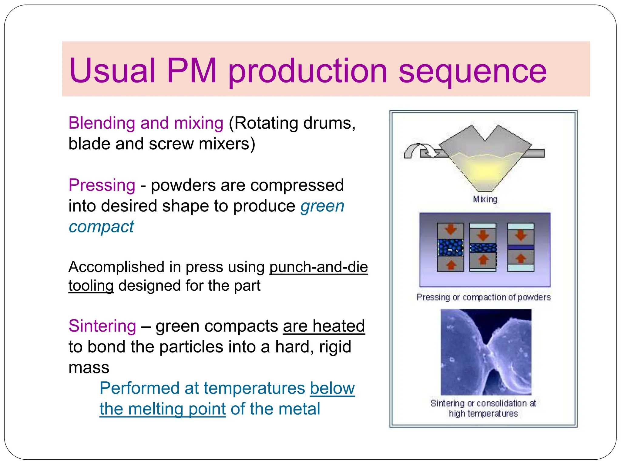
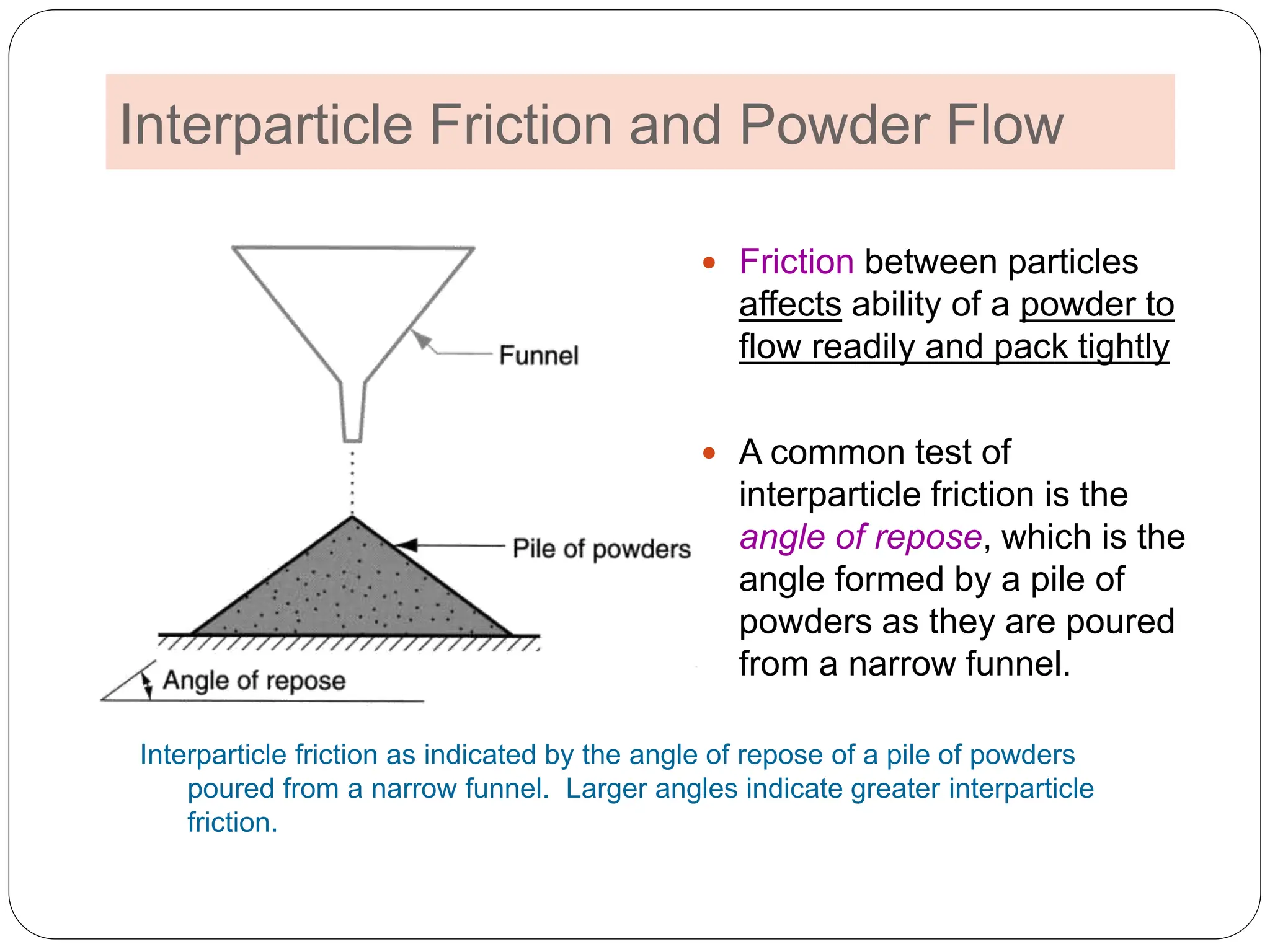
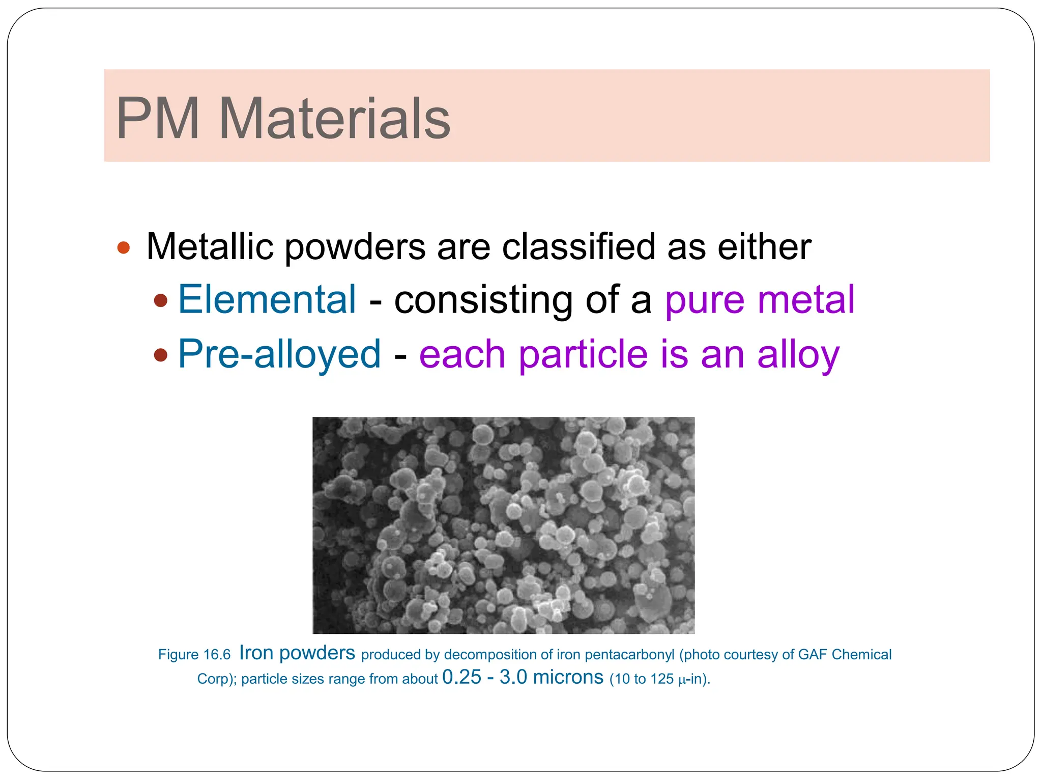
2. POWDER METALLURGY
2
1. The Characterization of Engineering
Powders
2. Production of Metallic Powders
3. Conventional Pressing and Sintering
4. Alternative Pressing and Sintering
Techniques
5. Materials and Products for PM
6. Design Considerations in Powder
Metallurgy
3. Modern powder
metallurgy dates
only back to the
early 1800
Powder Metallurgy (PM)
3
Metal processing technology in which parts are
produced from metallic powders
PM parts can be mass produced to net shape or near
net shape, eliminating or reducing the need for
subsequent machining
Certain metals that are difficult to fabricate by other
methods can be shaped by PM
Tungsten filaments for lamp bulbs are made by
PM
PM process wastes very little material - ~ 97% of
starting powders are converted to product
PM parts can be made with a specified level of
porosity, to produce porous metal parts
Examples: filters, oil-impregnated bearings and gears
4. Limitations and Disadvantages
4
High tooling and equipment costs
Metallic powders are expensive
Problems in storing and handling metal
powders
Degradation over time, fire hazards with
certain metals
Limitations on part geometry because metal
powders do not readily flow laterally in the
die during pressing
Variations in density throughout part may
be a problem, especially for complex
geometries
5. Usual PM production sequence
5
Blending and mixing (Rotating drums,
blade and screw mixers)
Pressing - powders are compressed
into desired shape to produce green
compact
Accomplished in press using punch-and-die
tooling designed for the part
Sintering – green compacts are heated
to bond the particles into a hard, rigid
mass
Performed at temperatures below
the melting point of the metal
6. PM Work Materials
6
Largest tonnage of metals are alloys
of iron, steel, and aluminum
Other PM metals include copper,
nickel, and refractory metals such as
molybdenum and tungsten
Metallic carbides such as tungsten
carbide are often included within the
scope of powder metallurgy
8. Engineering Powders
8
A powder can be defined as a finely divided particulate
solid
Engineering powders include metals and ceramics
Particle shapes
9. Measuring Particle Size
9
Most common method uses screens of different mesh sizes
Mesh count - refers to the number of openings per linear inch of
screen
A mesh count of 200 means there are 200 openings per
linear inch
Higher mesh count = smaller particle size
Figure Screen mesh for
sorting particle sizes.
10. Interparticle Friction and Powder Flow
10
Friction between particles
affects ability of a powder to
flow readily and pack tightly
A common test of
interparticle friction is the
angle of repose, which is the
angle formed by a pile of
powders as they are poured
from a narrow funnel.
Interparticle friction as indicated by the angle of repose of a pile of powders
poured from a narrow funnel. Larger angles indicate greater interparticle
friction.
11. Observations
11
Easier flow of particles correlates
with lower interparticle friction
Lubricants are often added to
powders to reduce interparticle
friction and facilitate flow during
pressing
12. Let’s check!
12
Smaller particle sizes show steeper angles or larger
particle sizes?!
Smaller particle sizes generally show
greater friction and steeper angles!
Finer
particles
13. Let’s check!
13
Which shape has the lowest interpartical friction?
Spherical shapes have the
lowest interpartical friction!
Little friction
between spherical
particles!
As shape deviates
from spherical,
friction between
particles tends to
increase
14. Particle Density Measures
14
True density - density of the true volume of
the material
The density of the material if the powders
were melted into a solid mass
Bulk density - density of the powders in the
loose state after pouring
Which one is smaller?!
Because of pores between particles, bulk density
is less than true density
15. Packing Factor
15
Typical values for loose
powders range between
0.5 and 0.7
Bulk density
true density
Packing factor =
• If powders of various sizes are present,
smaller powders will fit into spaces between
larger ones, thus higher packing factor
• Packing can be increased by vibrating the
powders, causing them to settle more tightly
• Pressure applied during compaction greatly
increases packing of powders through
rearrangement and deformation of particles
How can we increase the bulk density?
16. Porosity
16
Ratio of volume of the pores (empty spaces) in the
powder to the bulk volume
In principle
Porosity + Packing factor = 1.0
A highly porous ceramic
material (http://www.glass-
ceramics.uni-erlangen.de/)
17. PM Materials
17
Metallic powders are classified as either
Elemental - consisting of a pure metal
Pre-alloyed - each particle is an alloy
Figure 16.6 Iron powders produced by decomposition of iron pentacarbonyl (photo courtesy of GAF Chemical
Corp); particle sizes range from about 0.25 - 3.0 microns (10 to 125 -in).
18. PM Materials – Elemental
Powders
18
A pure metal in particulate form
Applications where high purity is important
Common elemental powders:
Iron
Aluminum
Copper
Elemental powders can be mixed with other metal
powders to produce alloys that are difficult to
formulate by conventional methods
Example: tool steels
19. PM Materials – Pre-Alloyed
Powders
19
Each particle is an alloy comprised of the
desired chemical composition
Common pre-alloyed powders:
Stainless steels
Certain copper alloys
High speed steel
20. PM Products
20
Gears, bearings, sprockets, fasteners, electrical
contacts, cutting tools, and various machinery parts
Advantage of PM: parts can be made to near net
shape or net shape
When produced in large quantities, gears and
bearings are ideal for PM because:
The geometry is defined in two dimensions
(cross section is uniform)
There is a need for porosity in the part to serve
as a reservoir for lubricant
22. Production of Metallic Powders
22
In general, producers of metallic powders are not
the same companies as those that make PM parts
Any metal can be made into powder form
Three principal methods by which metallic powders
are commercially produced
1. Atomization (by gas, water, also centrifugal one)
2. Chemical
3. Electrolytic
23. 23
High velocity gas stream flows through expansion nozzle,
siphoning molten metal from below and spraying it into
container
Figure 16.5 (a) gas
atomization method
Check other figures
as well (page 344)
Gas Atomization Method
24. Conventional Press and Sinter
24
After metallic powders have been produced, the
conventional PM sequence consists of:
1. Blending and mixing of powders
2. Compaction - pressing into desired shape
3. Sintering - heating to temperature below melting
point to cause solid-state bonding of particles and
strengthening of part
In addition, secondary operations are sometimes performed to
improve dimensional accuracy, increase density, and for other
reasons
25. Blending and Mixing of Powders
25
For successful results in compaction and
sintering, the starting powders must be
homogenized (powders should be blended and mixed)
Blending - powders of same chemistry but possibly
different particle sizes are intermingled
Different particle sizes are often blended to reduce
porosity
Mixing - powders of different chemistries are combined
26. Compaction
26
Application of high pressure to the powders to form
them into the required shape
Conventional compaction method is pressing, in
which opposing punches squeeze the powders
contained in a die
The workpart after pressing is called a green
compact, the word green meaning not yet fully
processed
The green strength of the part when pressed is
adequate for handling but far less than after
sintering
27. Conventional Pressing in PM
27
Pressing in PM: (1) filling
die cavity with powder by
automatic feeder; (2) initial
and (3) final positions of
upper and lower punches
during pressing, (4) part
ejection.
Watch the single- and double-punch operations
Fill Press Eject
28. Sintering
28
Heat treatment to bond the metallic particles, thereby
increasing strength and hardness
Usually carried out at between 70% and 90% of the
metal's melting point (absolute scale)
particle bonding is initiated at contact points
29. Densification and Sizing
29
Secondary operations are performed to increase density, improve
accuracy, or accomplish additional shaping of the sintered part
Repressing - pressing sintered part in a closed die to
increase density and improve properties
Sizing - pressing a sintered part to improve
dimensional accuracy
Coining - pressworking operation on a sintered part
to press details into its surface
Machining - creates geometric features that cannot
be achieved by pressing, such as threads, side
holes, and other details
30. Impregnation and Infiltration
30
Porosity is a unique and inherent characteristic of
PM technology
It can be exploited to create special products by
filling the available pore space with oils, polymers, or
metals
Two categories:
1. Impregnation
2. Infiltration
31. Impregnation
31
The term used when oil or other fluid is permeated
into the pores of a sintered PM part
Common products are oil-impregnated bearings,
gears, and similar components
Alternative application is when parts are impregnated with
polymer resins that seep into the pore spaces in liquid form
and then solidify to create a pressure tight part
32. Infiltration
32
Operation in which the pores of the PM part are filled
with a molten metal
The melting point of the filler metal must be below that of the
PM part
Resulting structure is relatively nonporous, and the
infiltrated part has a more uniform density, as well as
improved toughness and strength
TM (filler)<TM (Part)