Downloaded 25 times


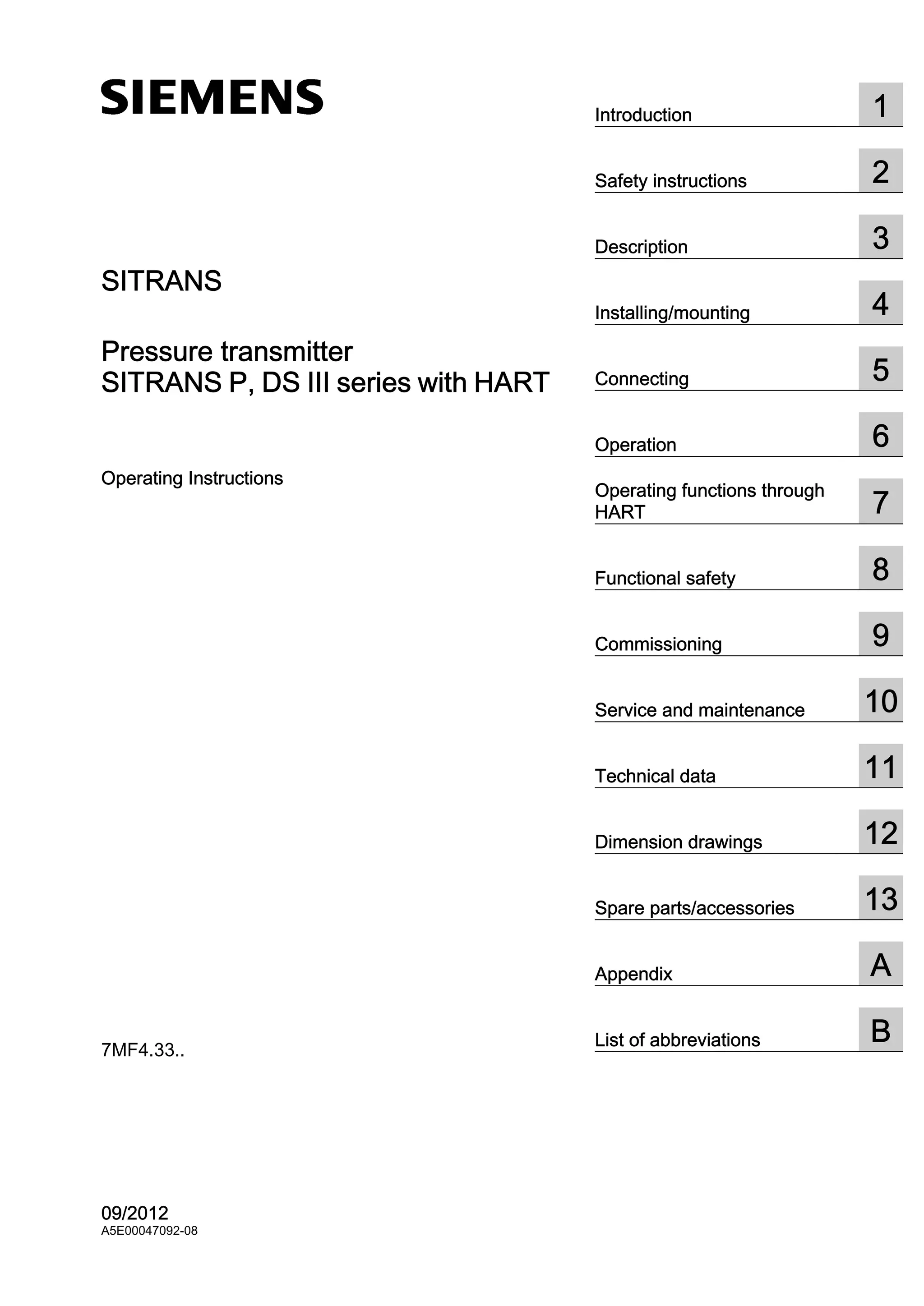
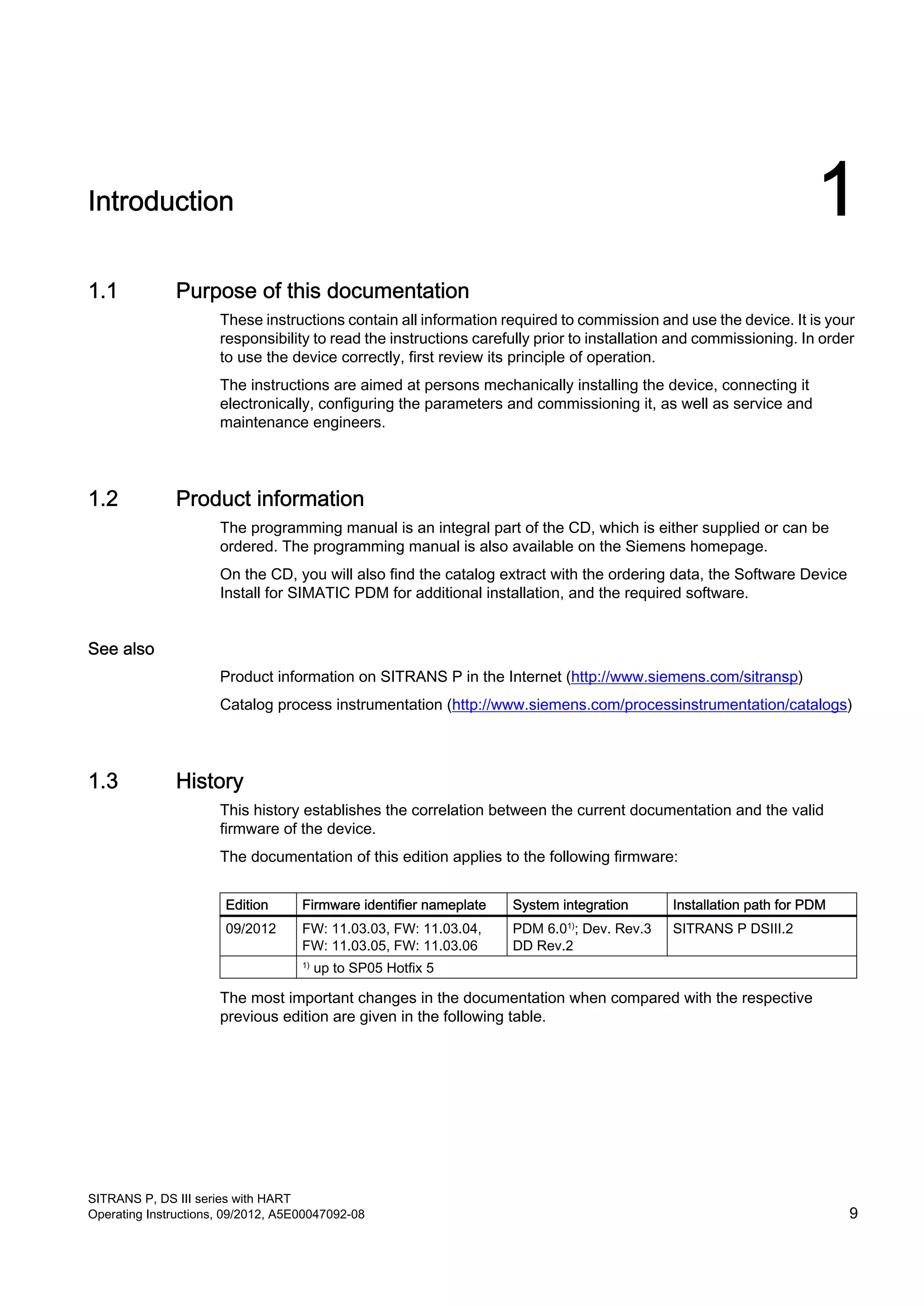

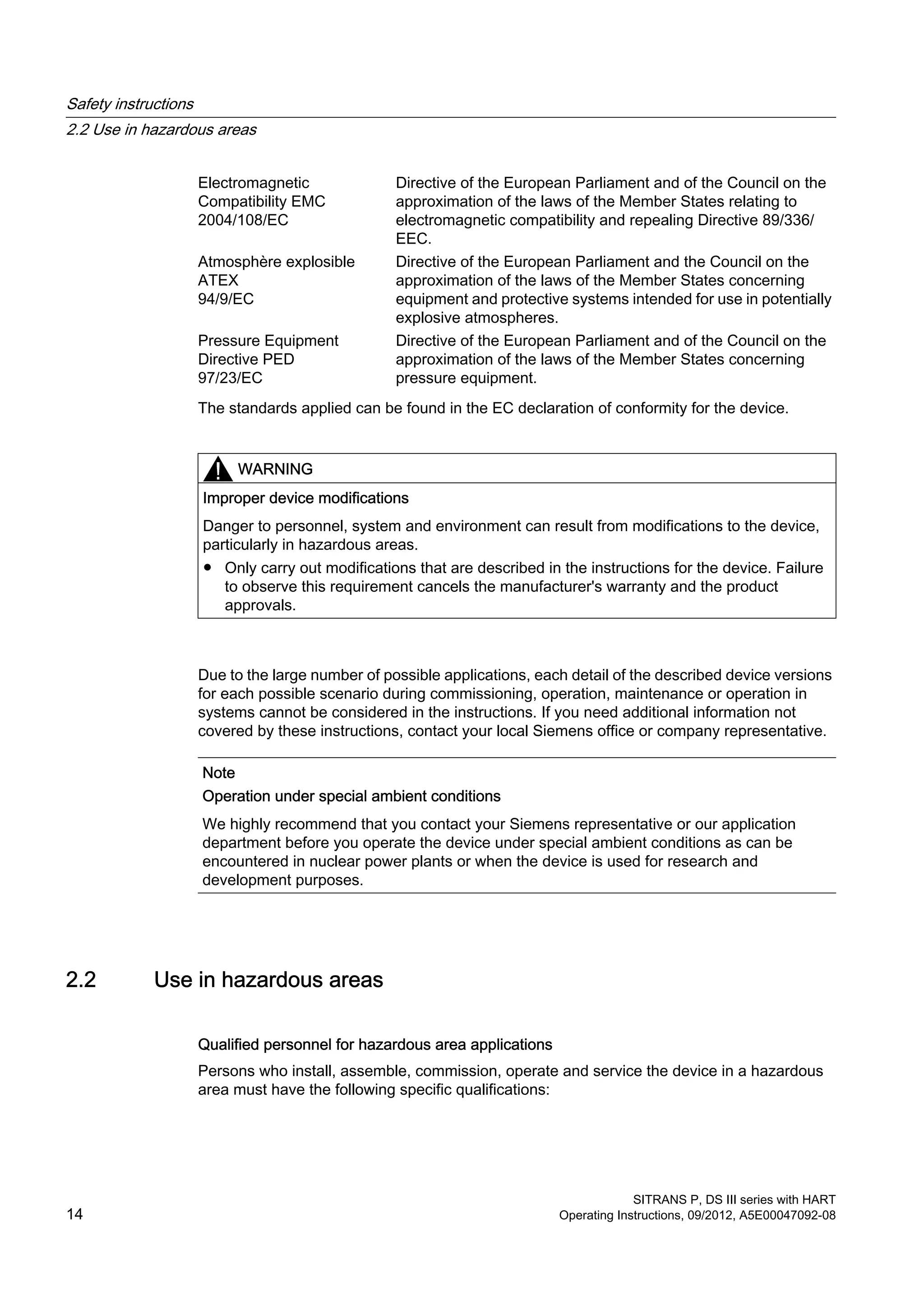

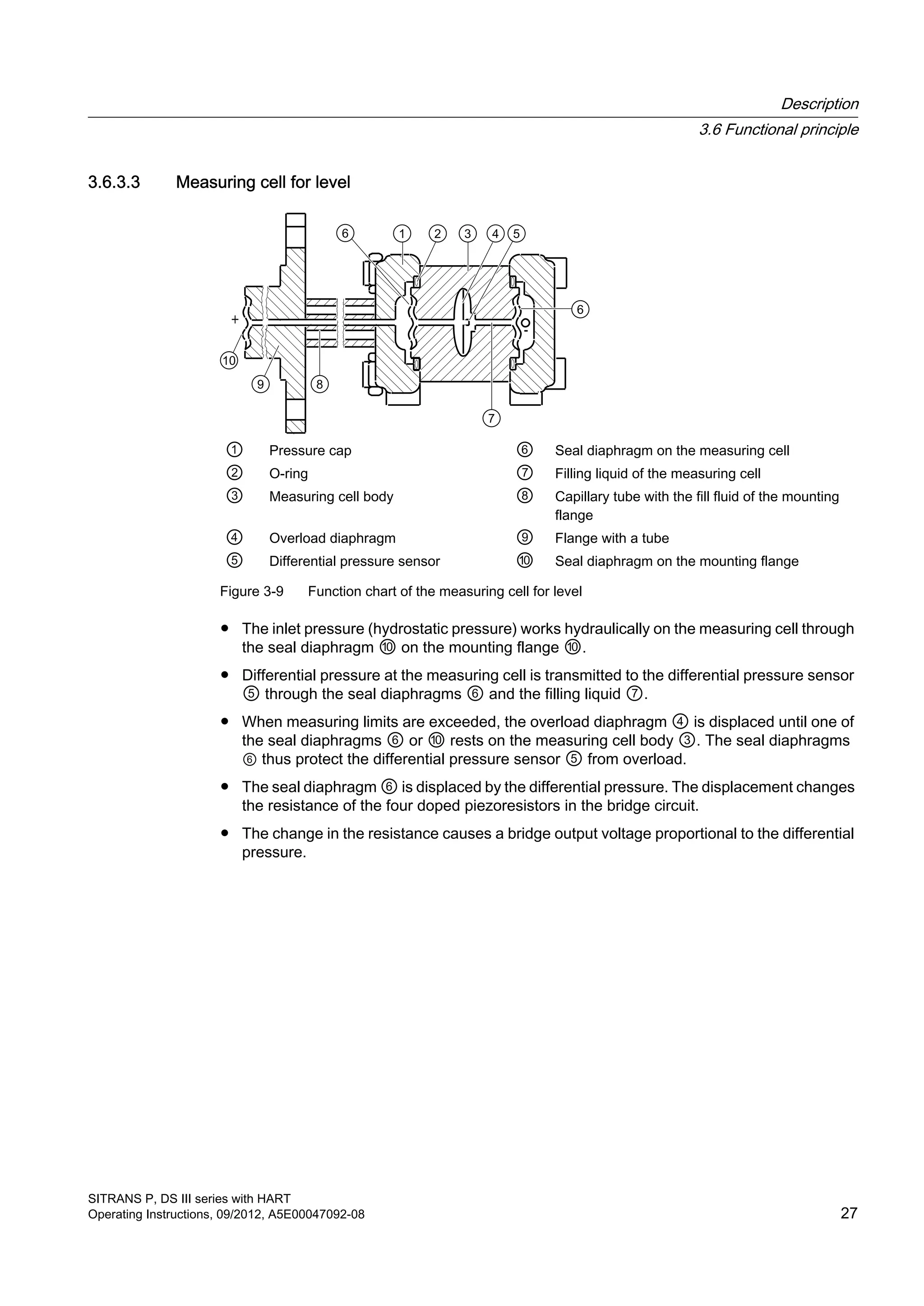


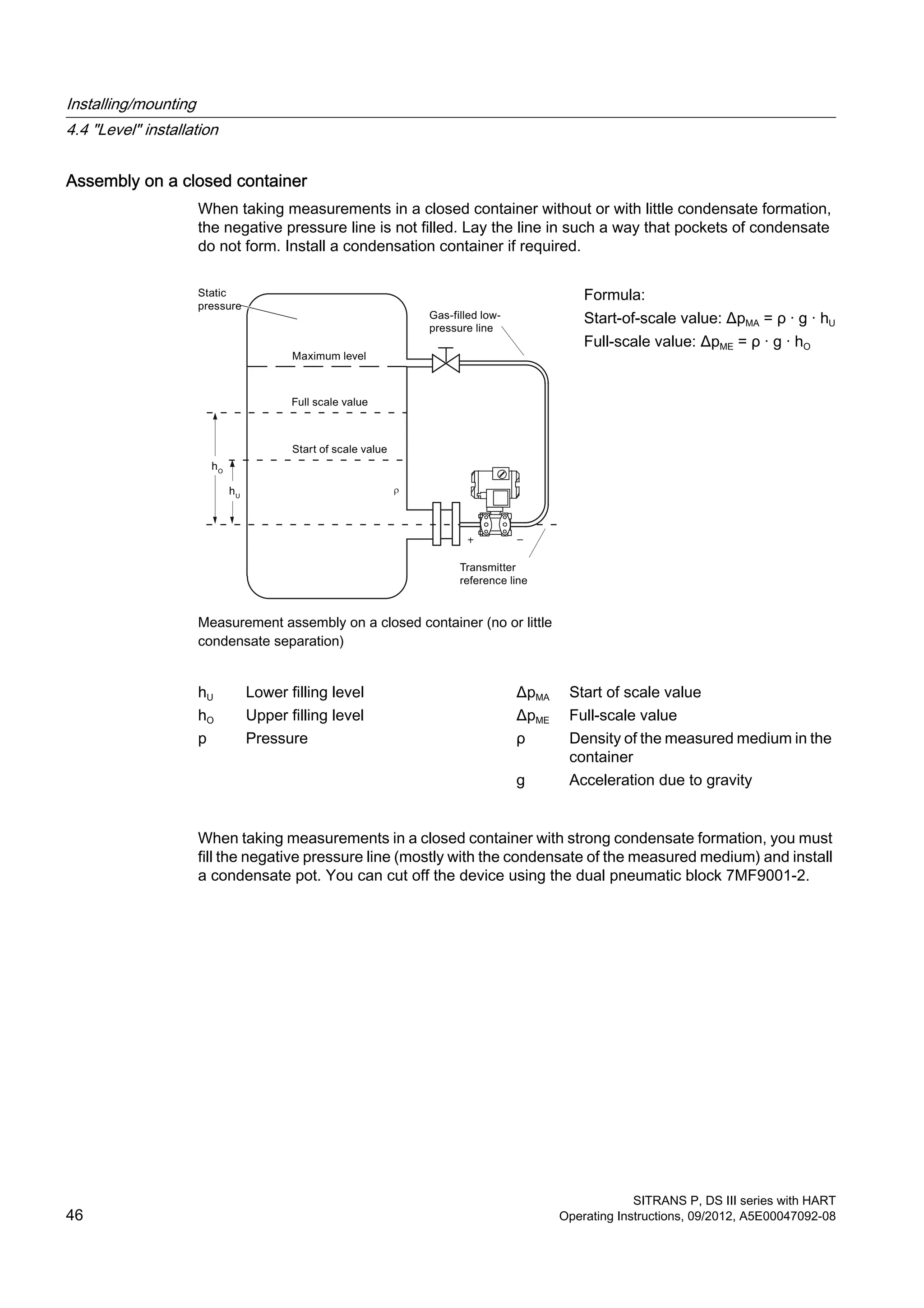

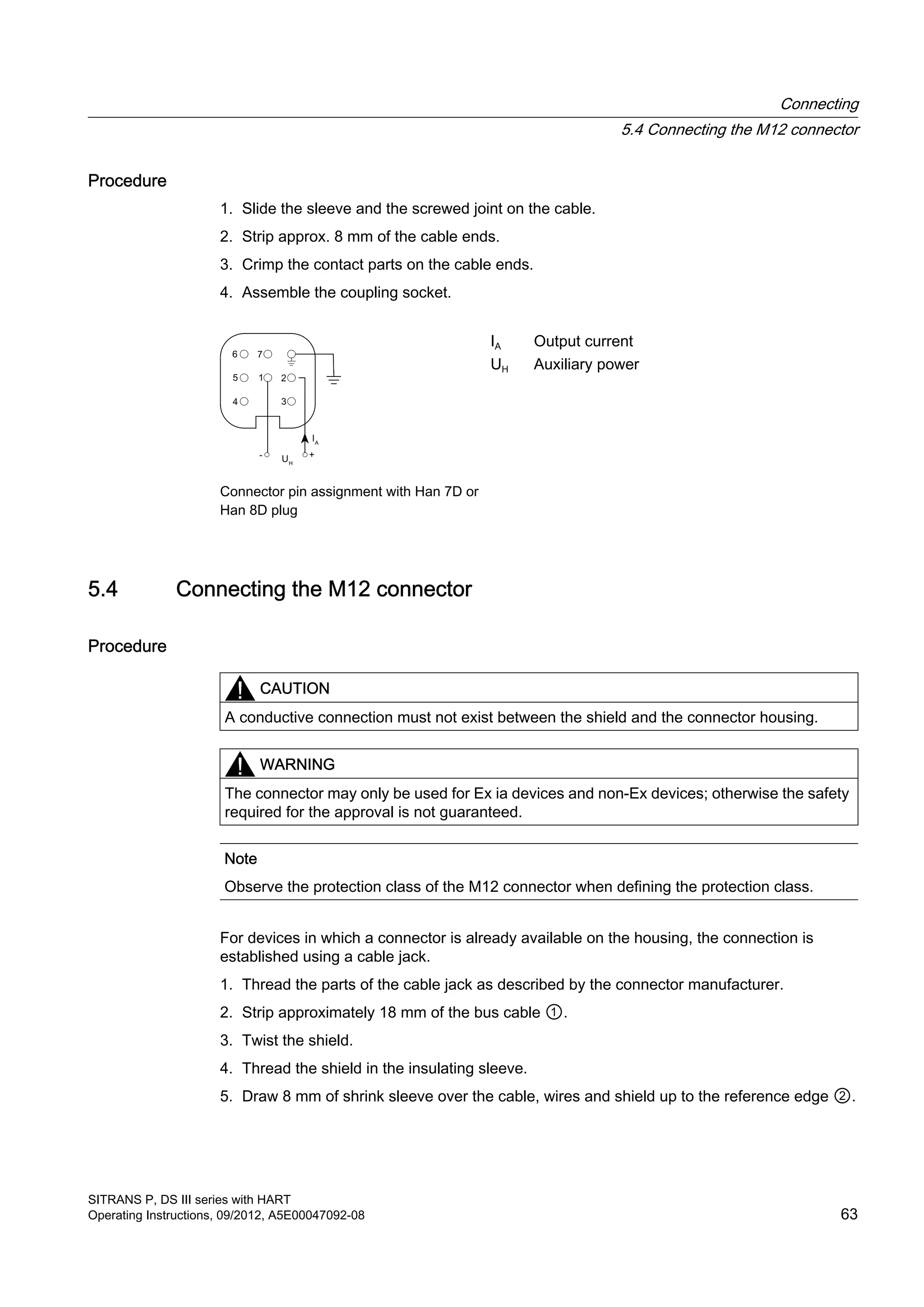
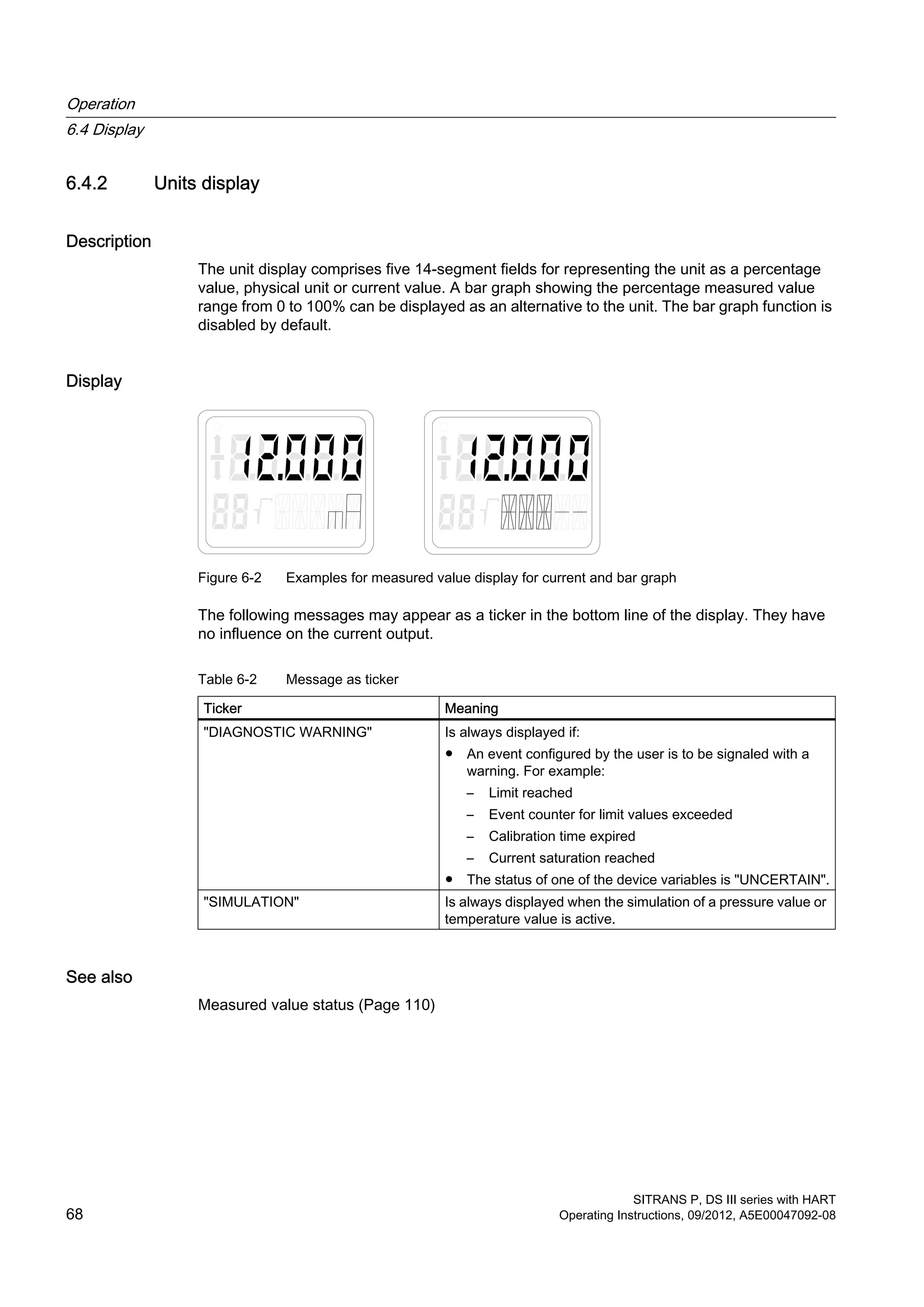
![Function Using buttons Using HART
Characteristic curve (lin., rad.)
(Not relevant for absolute
and gauge pressure)
Yes Yes
Customized characteristic curve No Yes
Diagnostic function No Yes
More operating functions for special applications are accessible through HART.
If a device does not have a display, its operations are limited. This is however not applicable
for selecting functions using HART.
6.2 Basic safety instructions
Note
Incorrect reproduction of the process pressure
If you have changed the basic functions of the pressure transmitter, the display and the
measurement output could be set such that the actual process pressure is not reproduced.
Therefore, check the basic parameters before commissioning.
6.3 Instructions for operation
The following rules are applicable for the operation of the pressure transmitter:
● The device counts numerical values always in an ascending order step by step starting
from the least significant digit displayed.
If you keep the button pressed for a longer time, it counts the next higher digit displayed.
This procedure is used for fast coarse adjustment over a wide number range. Release the
[↑] or [↓] button again for fine adjustment. Press the button again.
Violations of the measured value limits are output on the display by or .
● The keyboard must have been unlocked in order to operate the device using the keyboard.
● If you are operating the transmitter locally, write access is denied through HART during this
time.
However, it is always possible to read the data, e.g. measured values.
Note
The setting is saved and the measured values are automatically displayed again if more
than two minutes have passed after a button was pressed for the last time.
The operating instructions in the "Local operation without display" section apply if the
device has been delivered with a blind cover.
Operation
6.3 Instructions for operation
SITRANS P, DS III series with HART
66 Operating Instructions, 09/2012, A5E00047092-08](https://image.slidesharecdn.com/a5e00047092-07ends3hartexoien-us-150107073133-conversion-gate02/75/Manual-trm-siemens-68-2048.jpg)
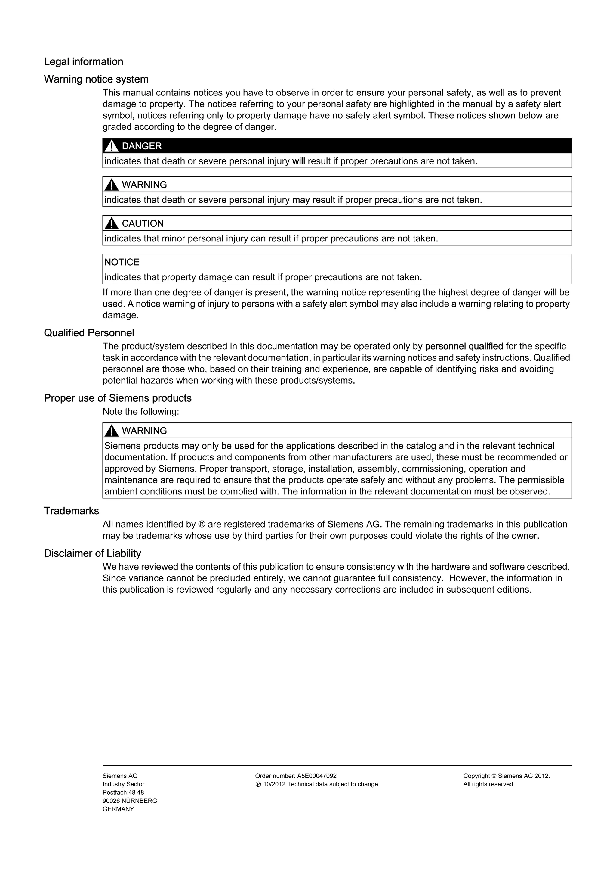
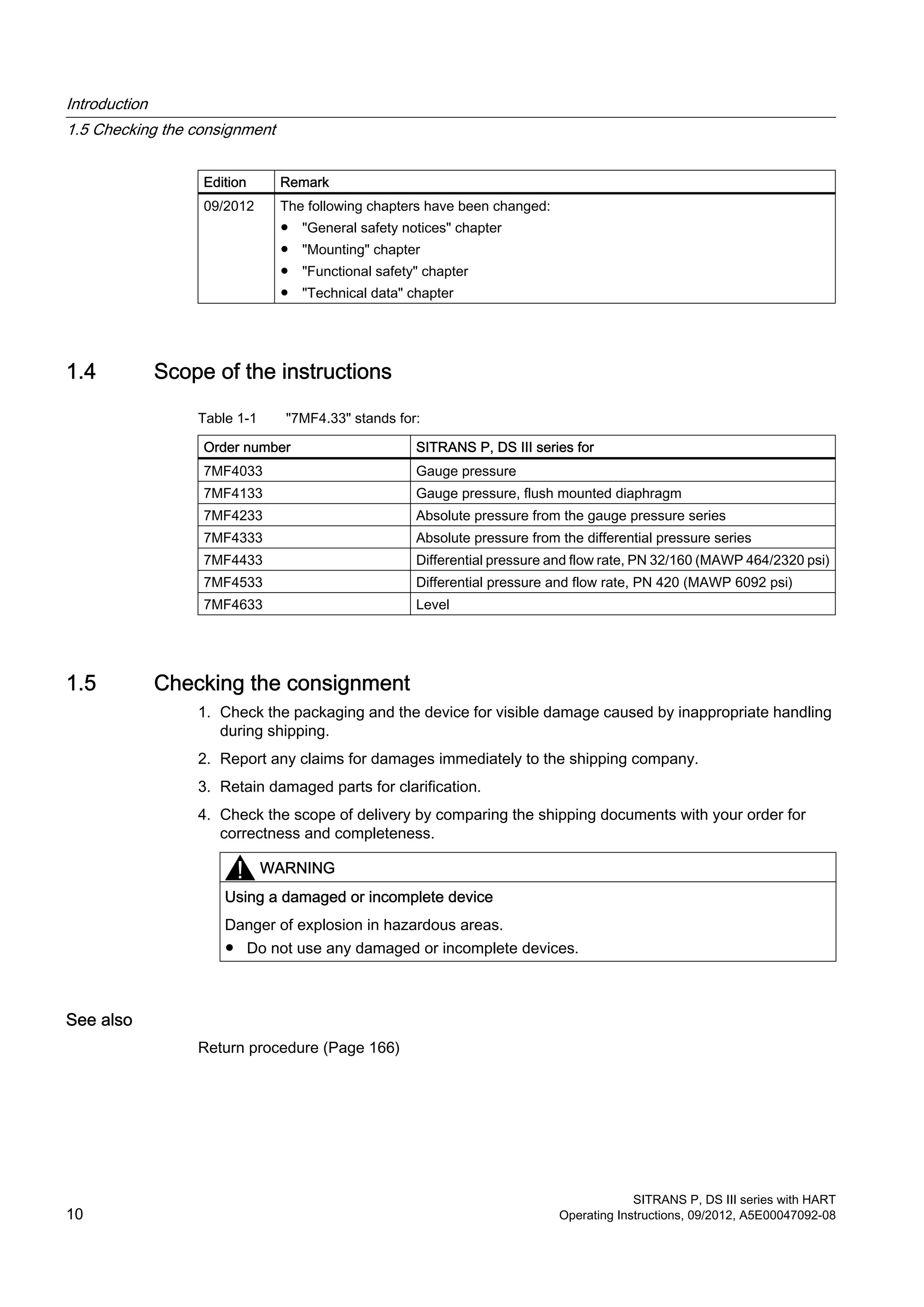
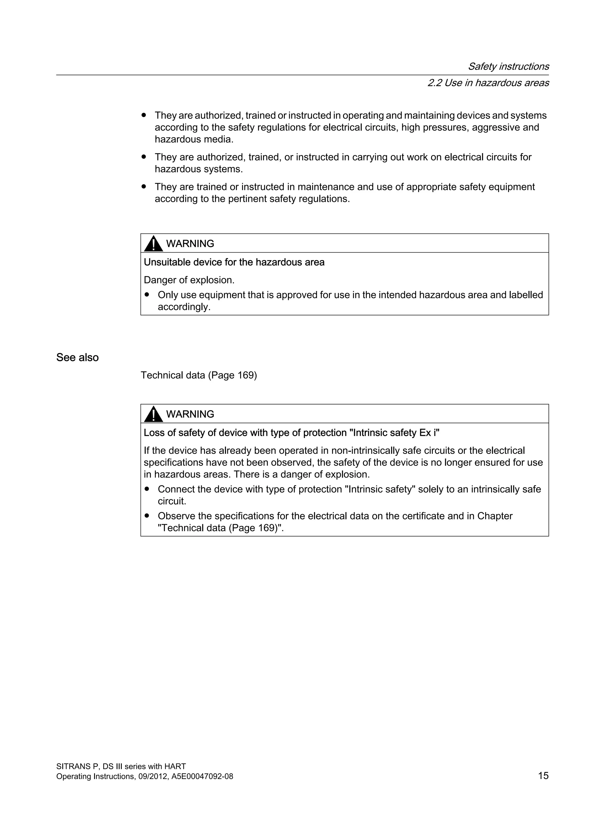
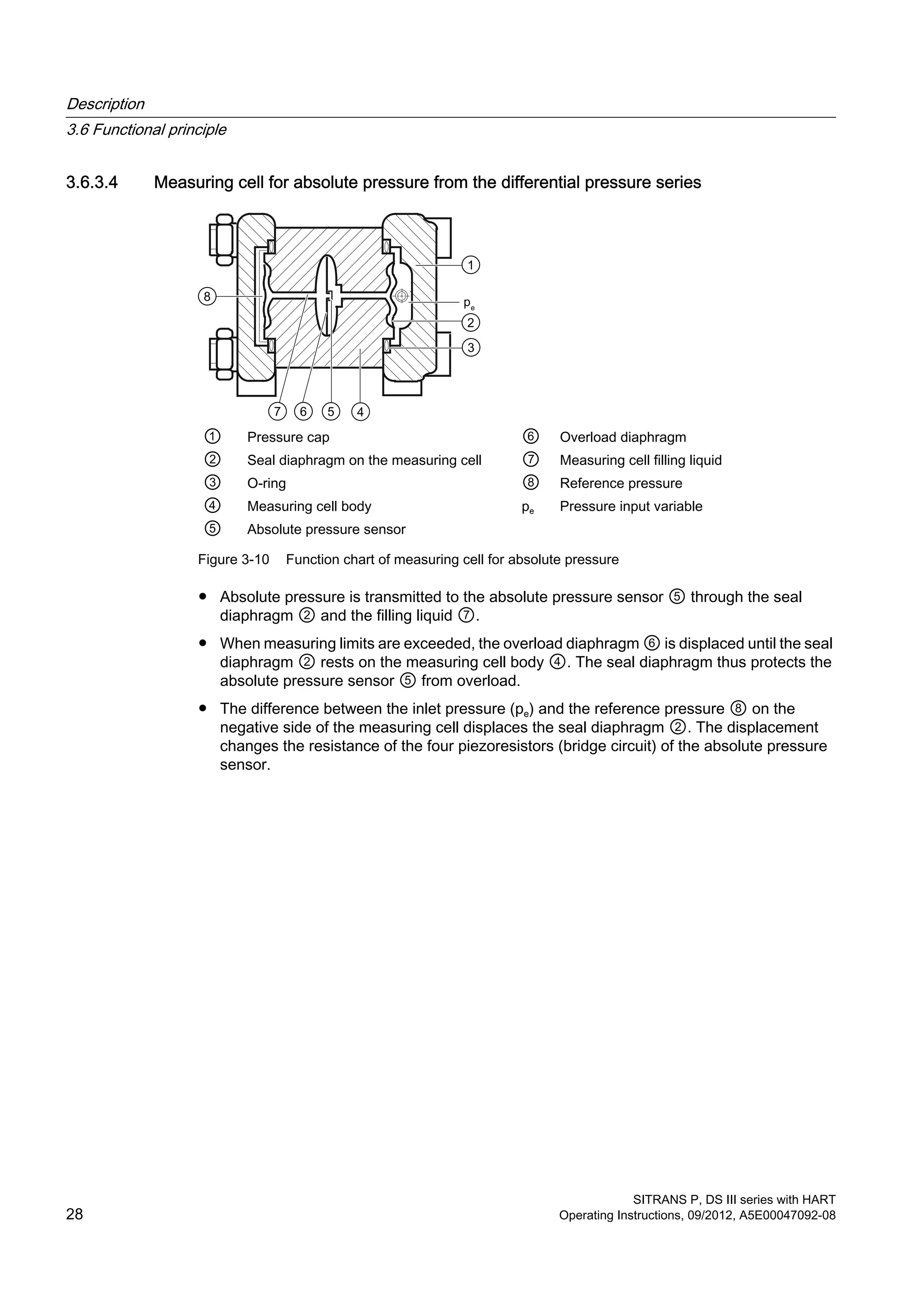
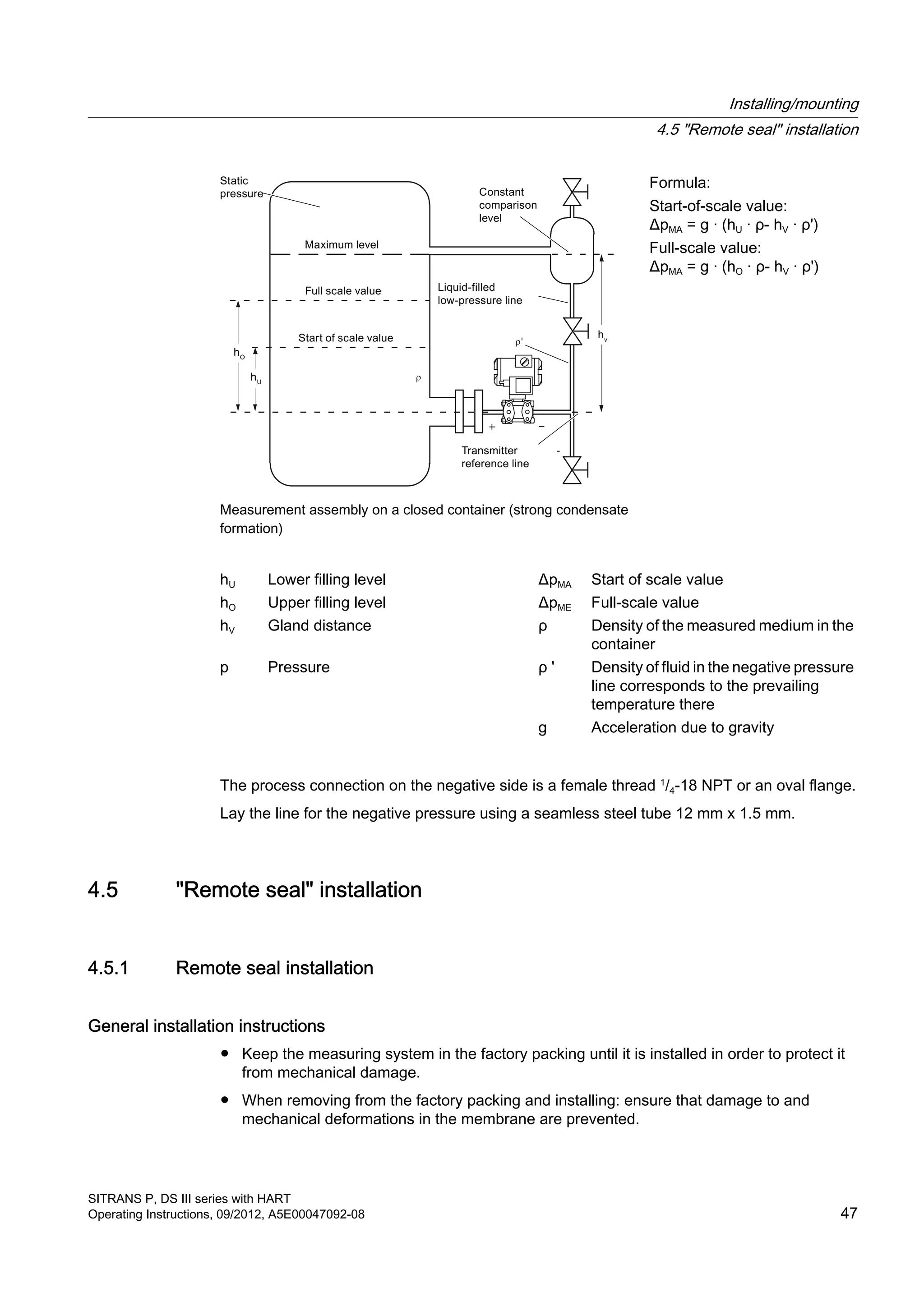
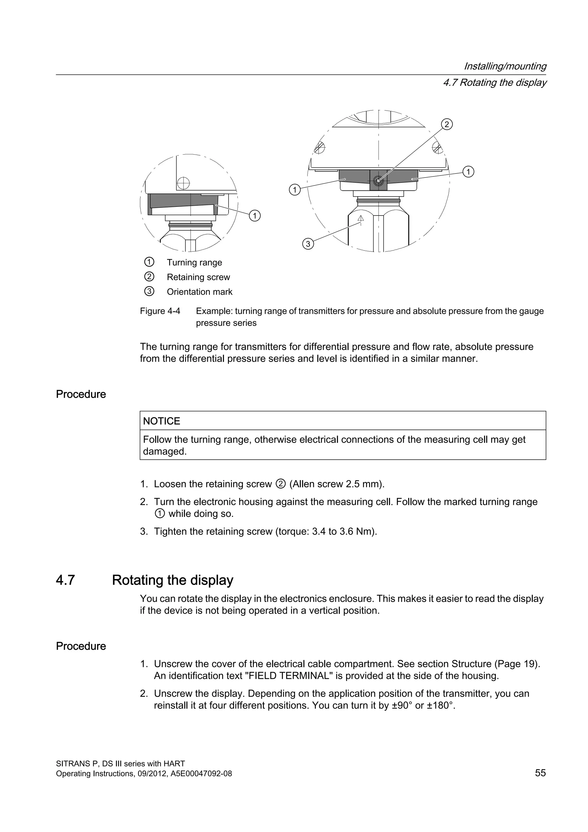
![Operating functions
Note
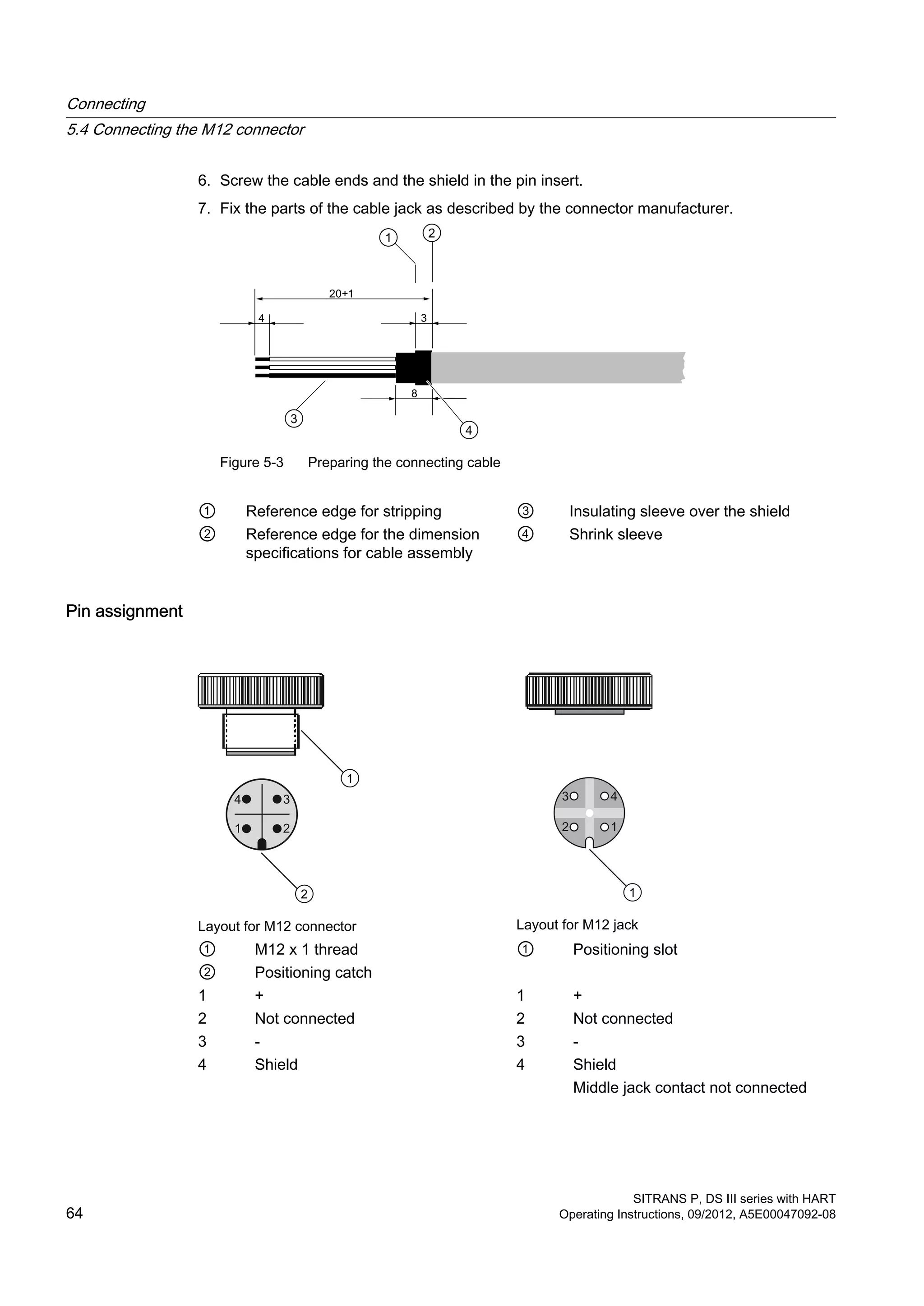
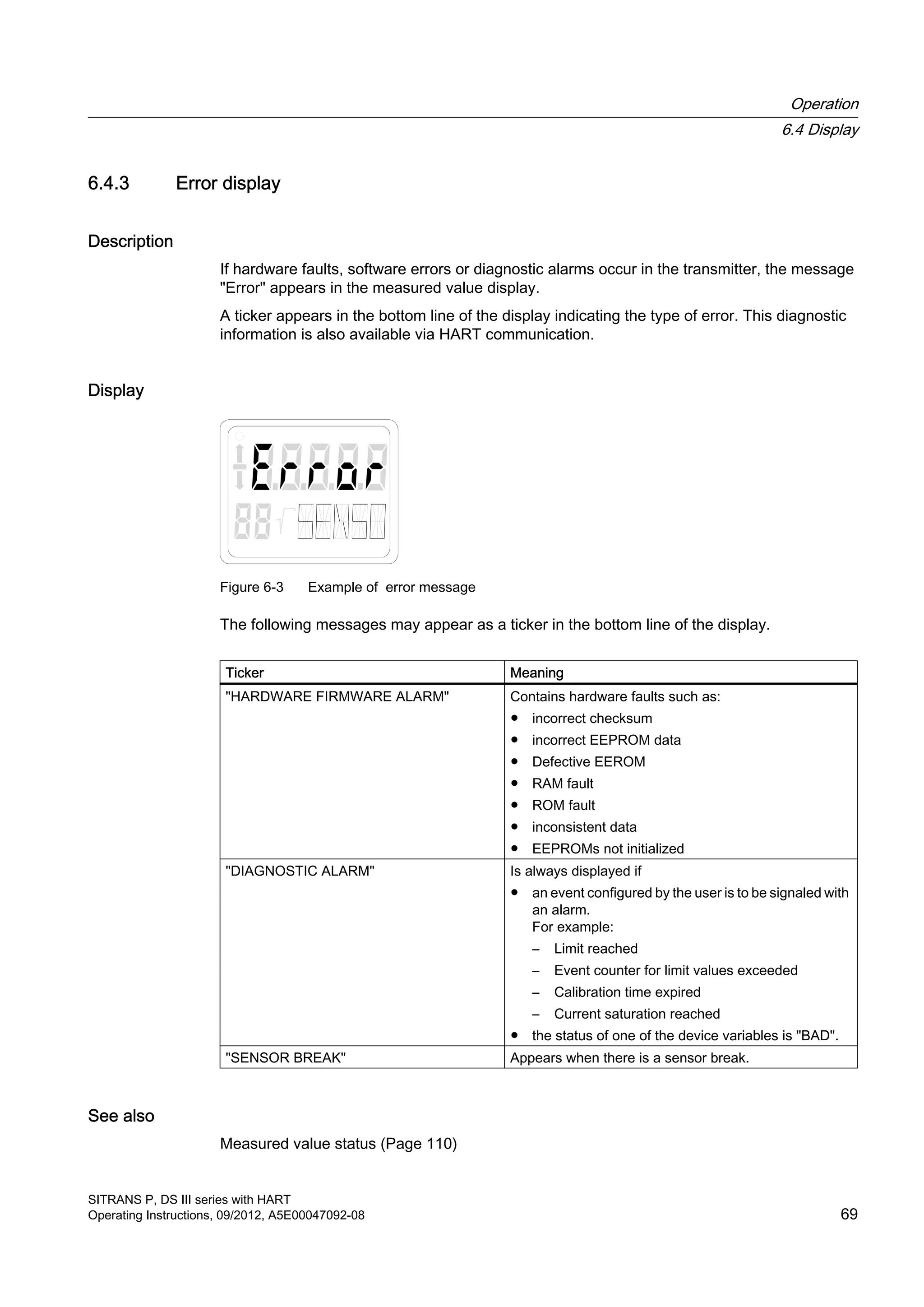
Zero point calibration
For absolute pressure transmitters, the start of scale value is at vacuum.
A zero point calibration with transmitters which do not measure absolute pressure leads to
faulty settings.
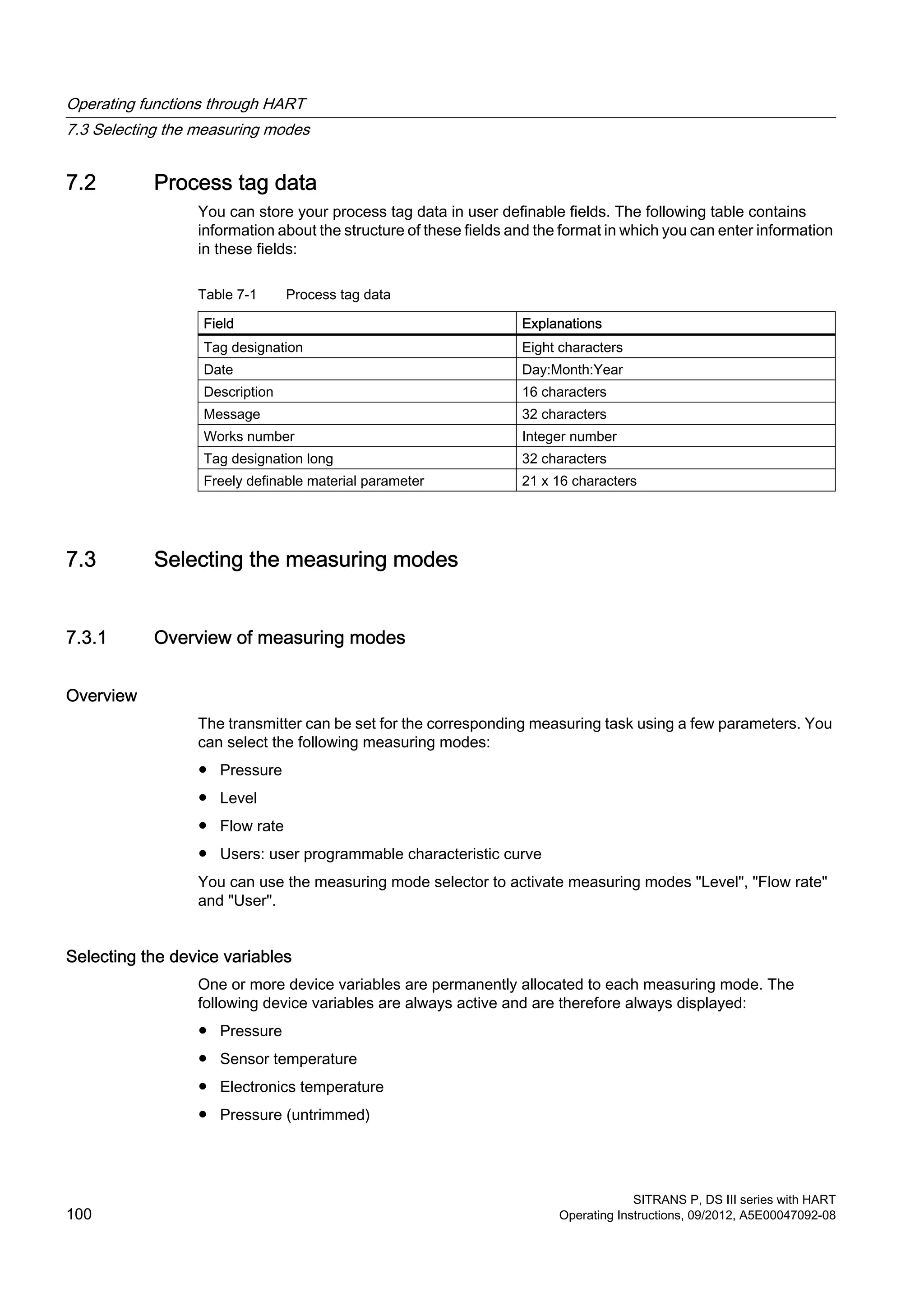
Table 6-4 Operating functions using keys
Function Mode Key function Display, explanations
[M] [↑] [↓] [↑] and [↓]
Measured value The
modes
are
select
ed
here.
The current measured value is displayed as you
have adjusted it in the "Measured value display,
mode 13" function.
Start of scale value
(only in "Pressure"
measuring mode)
2 Current
higher
Current
lower
Set to 4 mA Output current in mA
Full scale value
(only in "Pressure"
measuring mode)
3 Current
higher
Current
lower
Set to 20 mA Output current in mA
Electrical damping 4 Damping
higher
Damping
lower
Set to 0 Time constant T63 in seconds
Adjustment range: 0.0 s to 100.0 s
Start of scale value
in the so-called blind
adjustment
5 Pressure
higher
Pressure
lower
Set the start
of scale value
to 0
Start of scale value in the selected pressure unit
Full scale value in
the so-called blind
adjustment
6 Pressure
higher
Pressure
lower
Set the full
scale value to
upper
measuring
limit
Full scale value in the selected pressure unit
Zero point
calibration (position
correction)
7 Correction
value
higher
Correction
value lower
execute Ventilate the transmitter for gauge pressure,
differential pressure, flow rate or level.
Evacuate the transmitter for absolute pressure
(< 0.1‰ of the measuring span).
(Start of scale value remains unaffected)
Measured value in pressure unit
Current transmitter 8 Current
higher
Current
lower
switch on constant output current in mA
"3.6"; "4", "12", "20" or "22.8"
Switch off using the [M] key.
Output current in
case of fault
9 Switch between lower
fault current and upper
fault current.
lower fault
current
selected output current possible: Fault current
limits adjusted by user
Operation
6.5 Local operation
SITRANS P, DS III series with HART
Operating Instructions, 09/2012, A5E00047092-08 73](https://image.slidesharecdn.com/a5e00047092-07ends3hartexoien-us-150107073133-conversion-gate02/75/Manual-trm-siemens-75-2048.jpg)
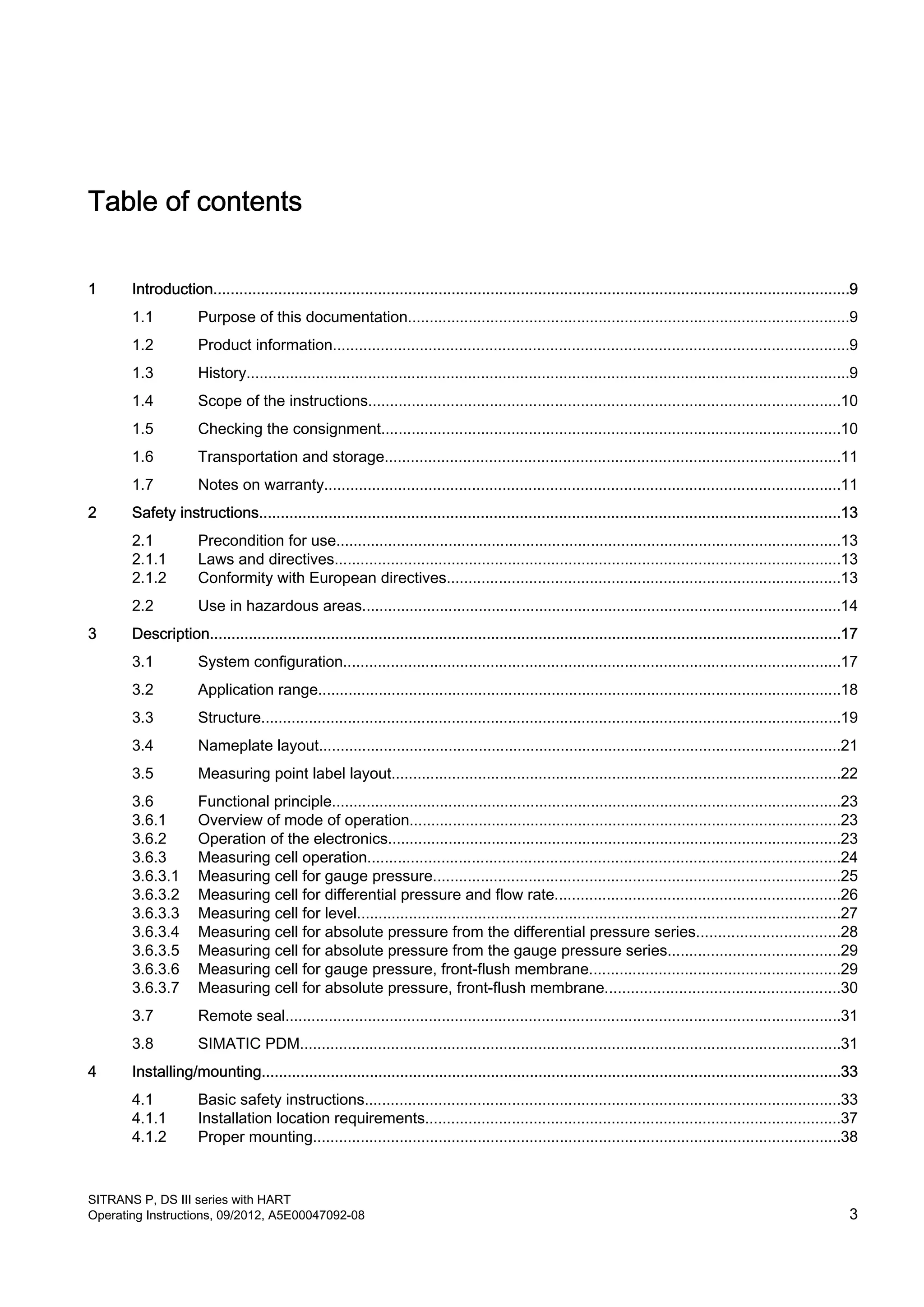
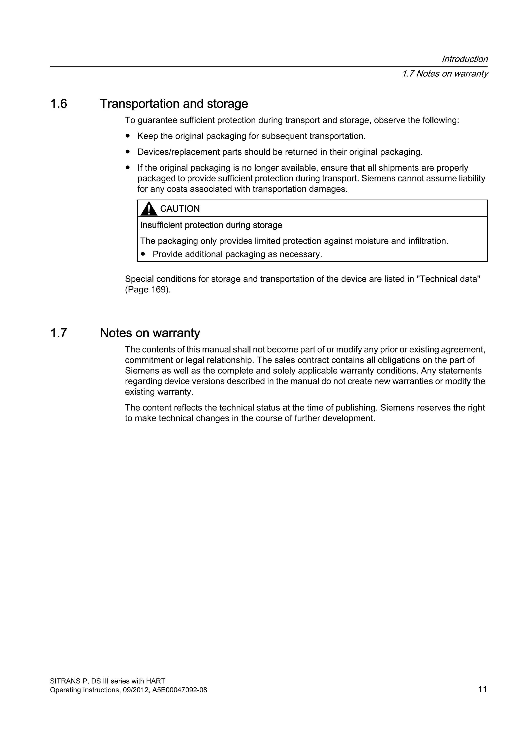
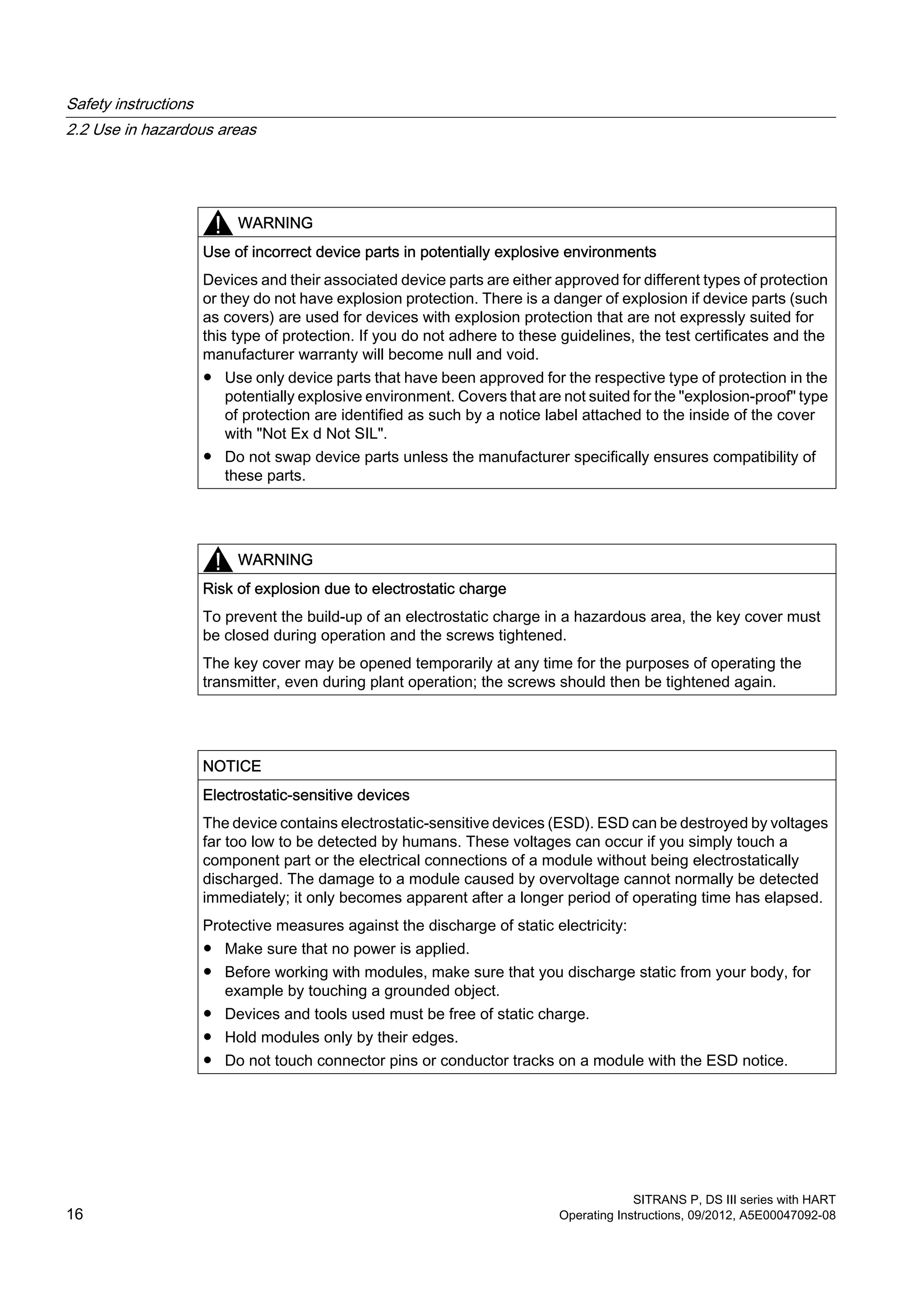
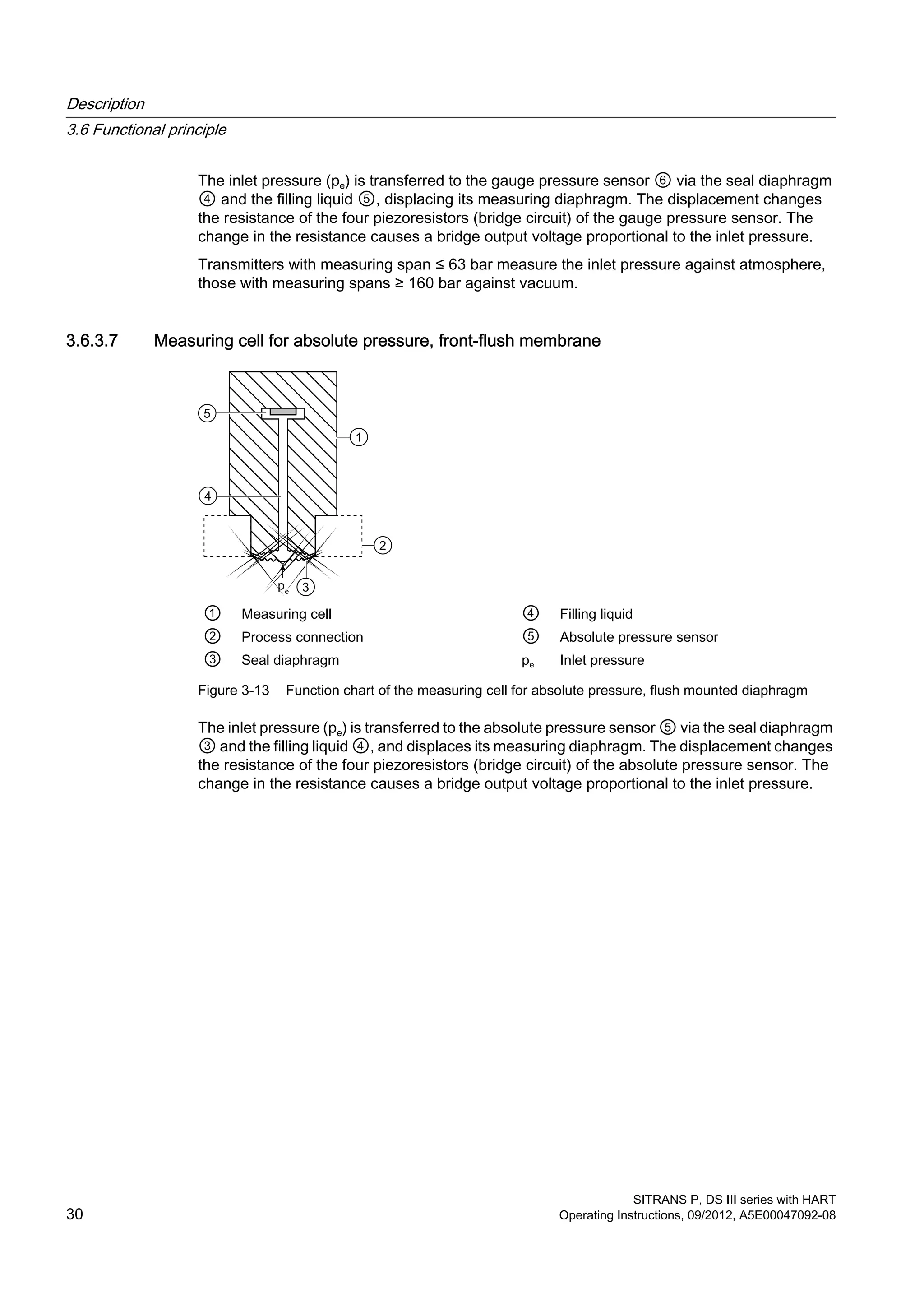
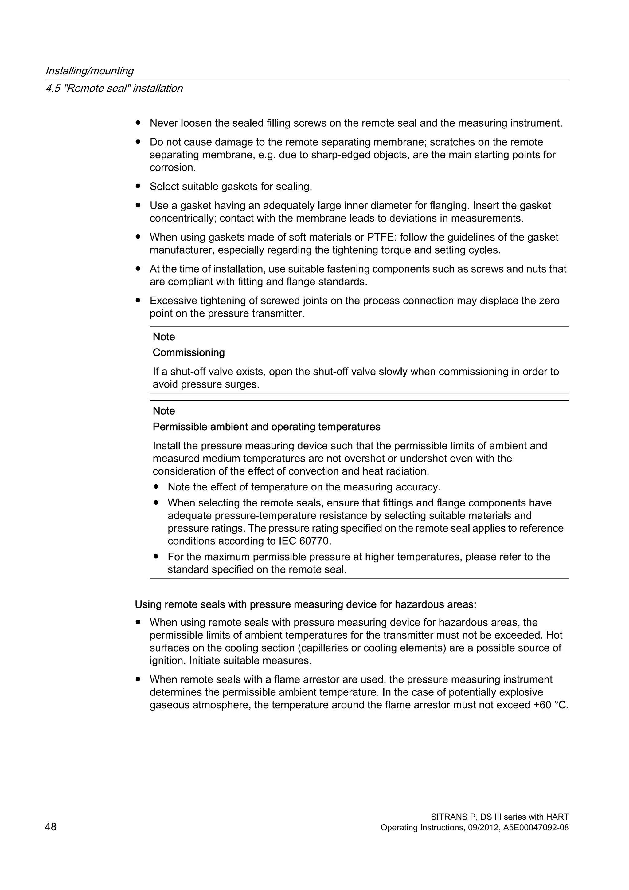
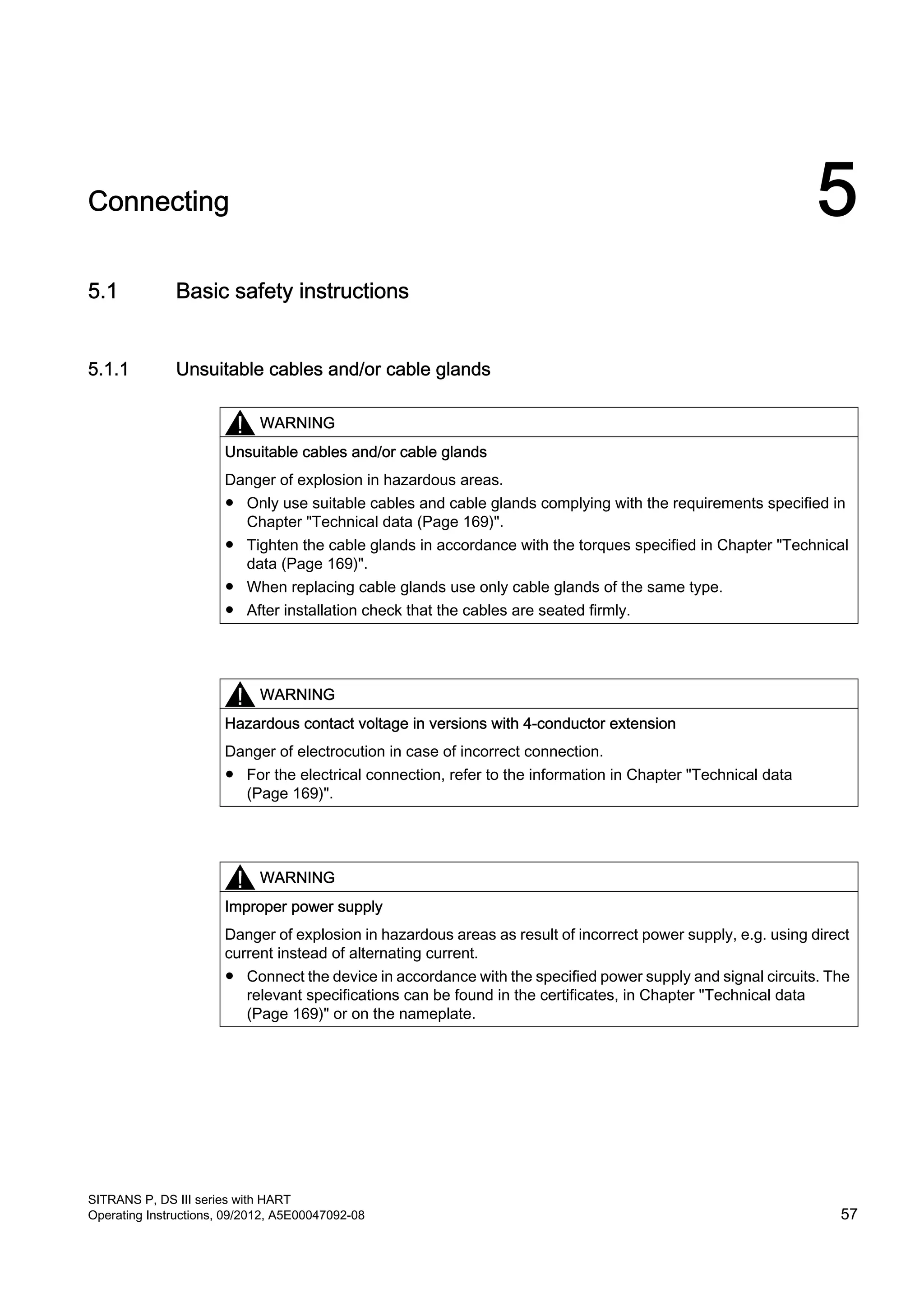
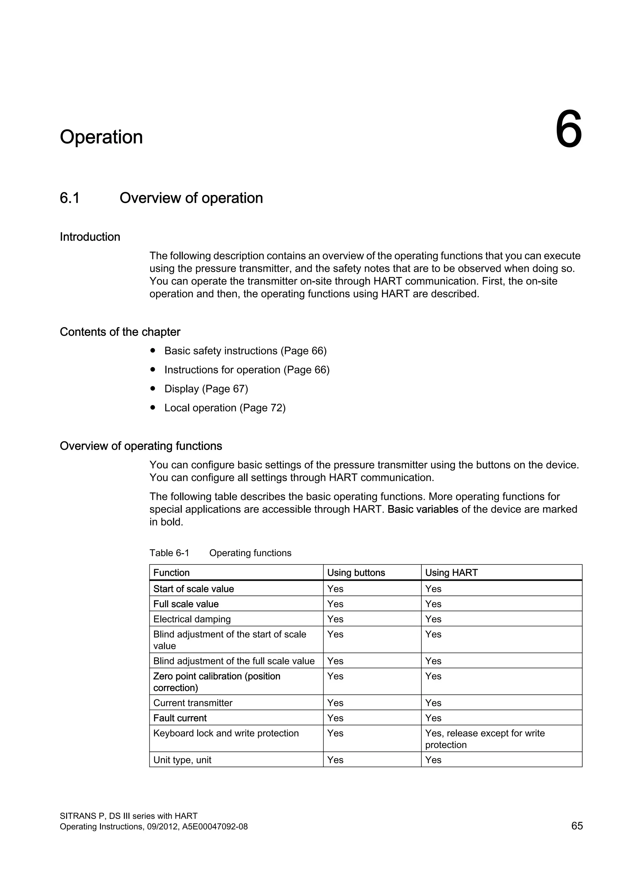
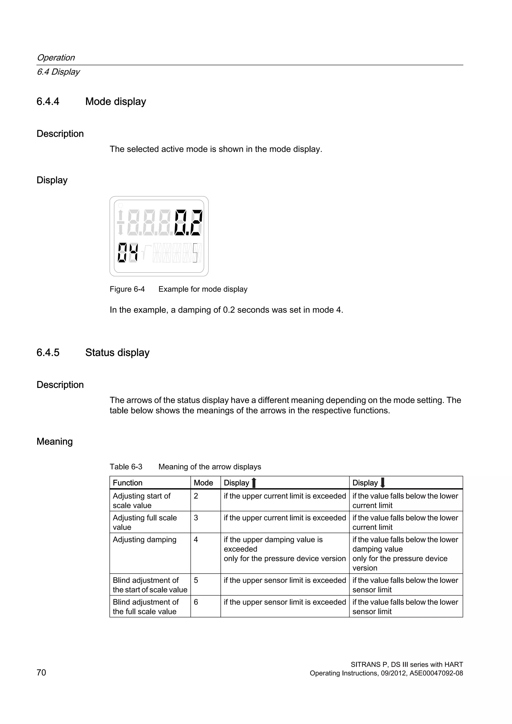
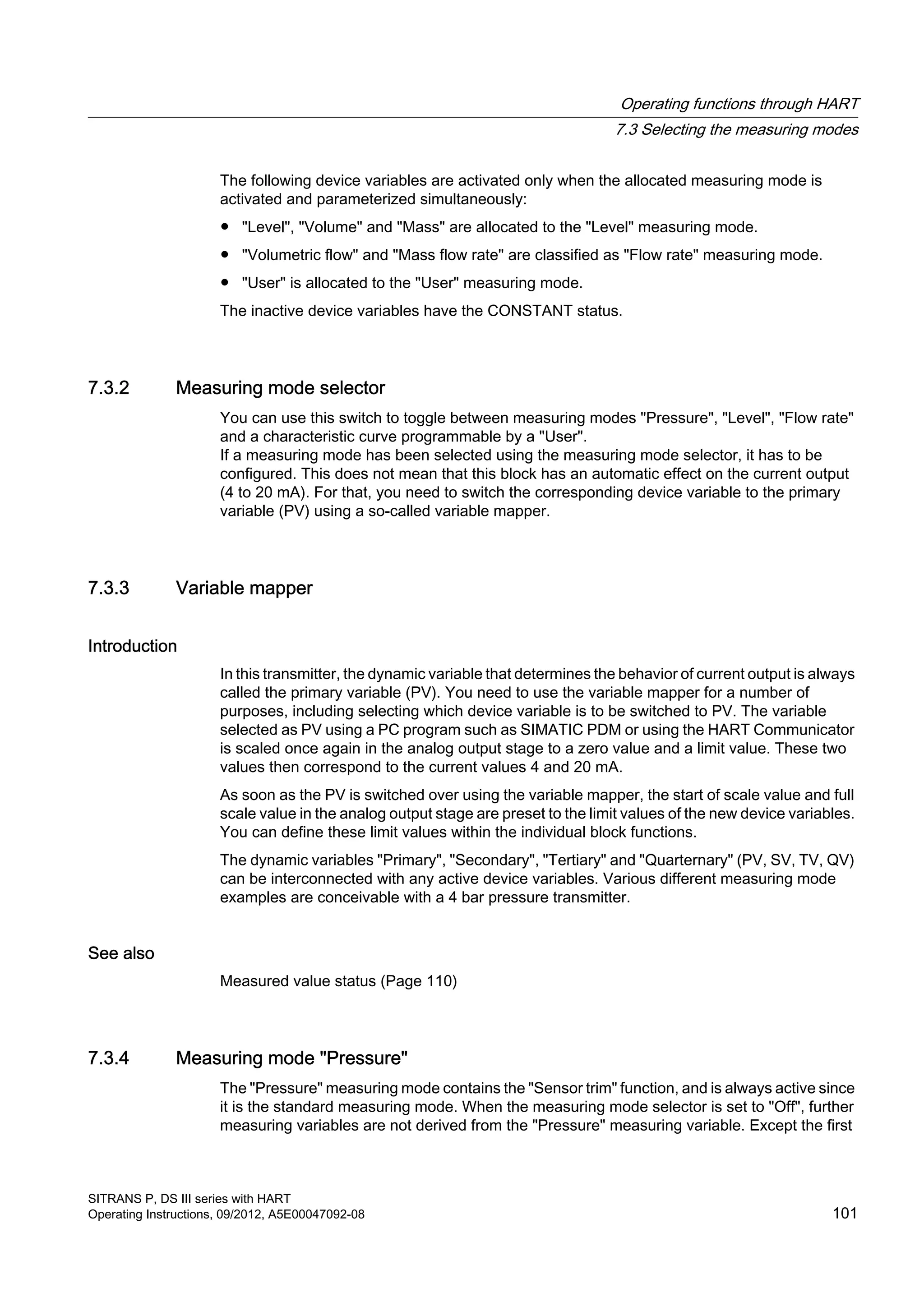
![Function Mode Key function Display, explanations
[M] [↑] [↓] [↑] and [↓]
Key lock or function
lock
10 Switch between the five
functions
– 0 None
LA all locked
LO all locked except for start of scale value
LS all locked except for start of scale value
and full scale value
L Write protection
Operation via HART not possible.
Characteristic
curve1)
11 Switch between the four
functions
linear lin linear
srlin square root extracting (linear up to the
application point)
sroff Square root extracting
(deactivated up to the application point)
srli2 square root extracting (linear up to the
application point 10%)
Application point of
the square root
extracting
characteristic curve1)
12 Greater Smaller 10% flow rate Adjustment range of 5 to 15% flow rate.
Measured value
display
13 Select from three options. – ● Display type (input value)
● Output current in mA
● Measured value in %
Unit 14 Select from the table for
measured value display.
In each case,
the first value
from the table
of the
physical unit
Physical unit
1)
Not relevant for gauge and absolute pressure)
See also
Overview of operation (Page 65)
Operating functions through HART communication (Page 99)
6.5.2 Operation using buttons
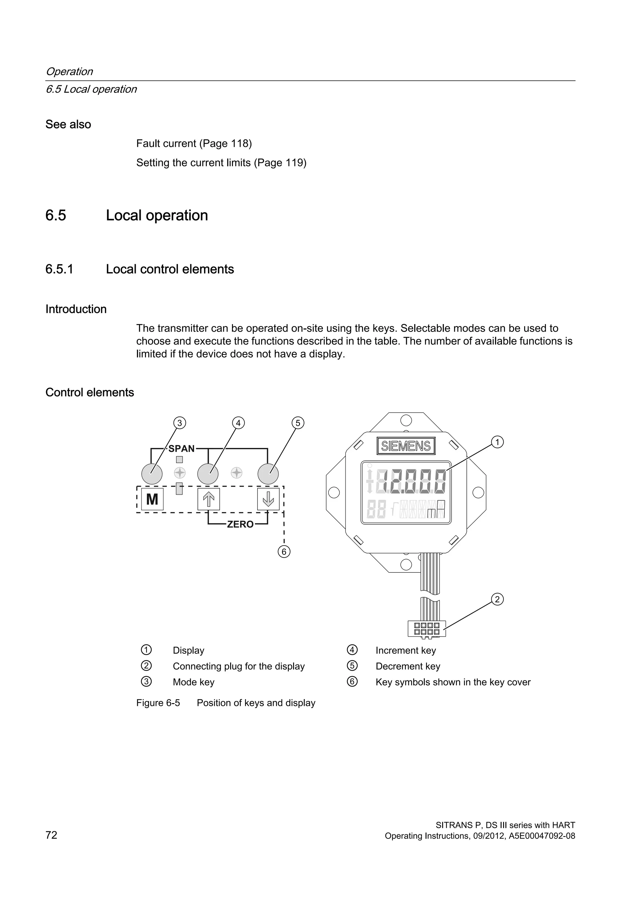
Introduction
This overview informs you about the most important safety notes to be observed when
operating the pressure transmitter. Furthermore, the overview guides you in adjusting the
operating functions on site.
Condition
The keyboard must have been unlocked in order to operate the device using the buttons.
Operation
6.5 Local operation
SITRANS P, DS III series with HART
74 Operating Instructions, 09/2012, A5E00047092-08](https://image.slidesharecdn.com/a5e00047092-07ends3hartexoien-us-150107073133-conversion-gate02/75/Manual-trm-siemens-76-2048.jpg)
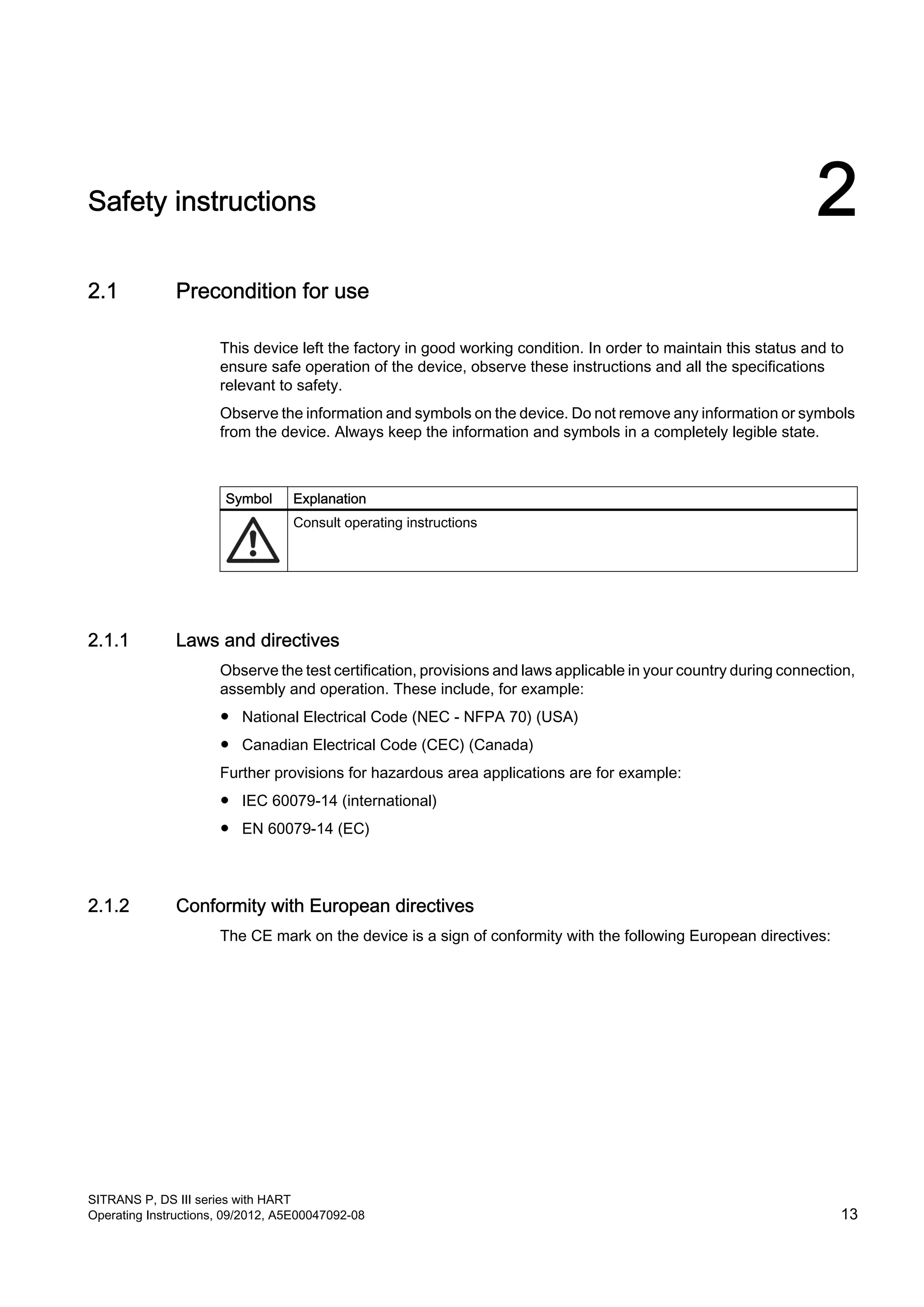
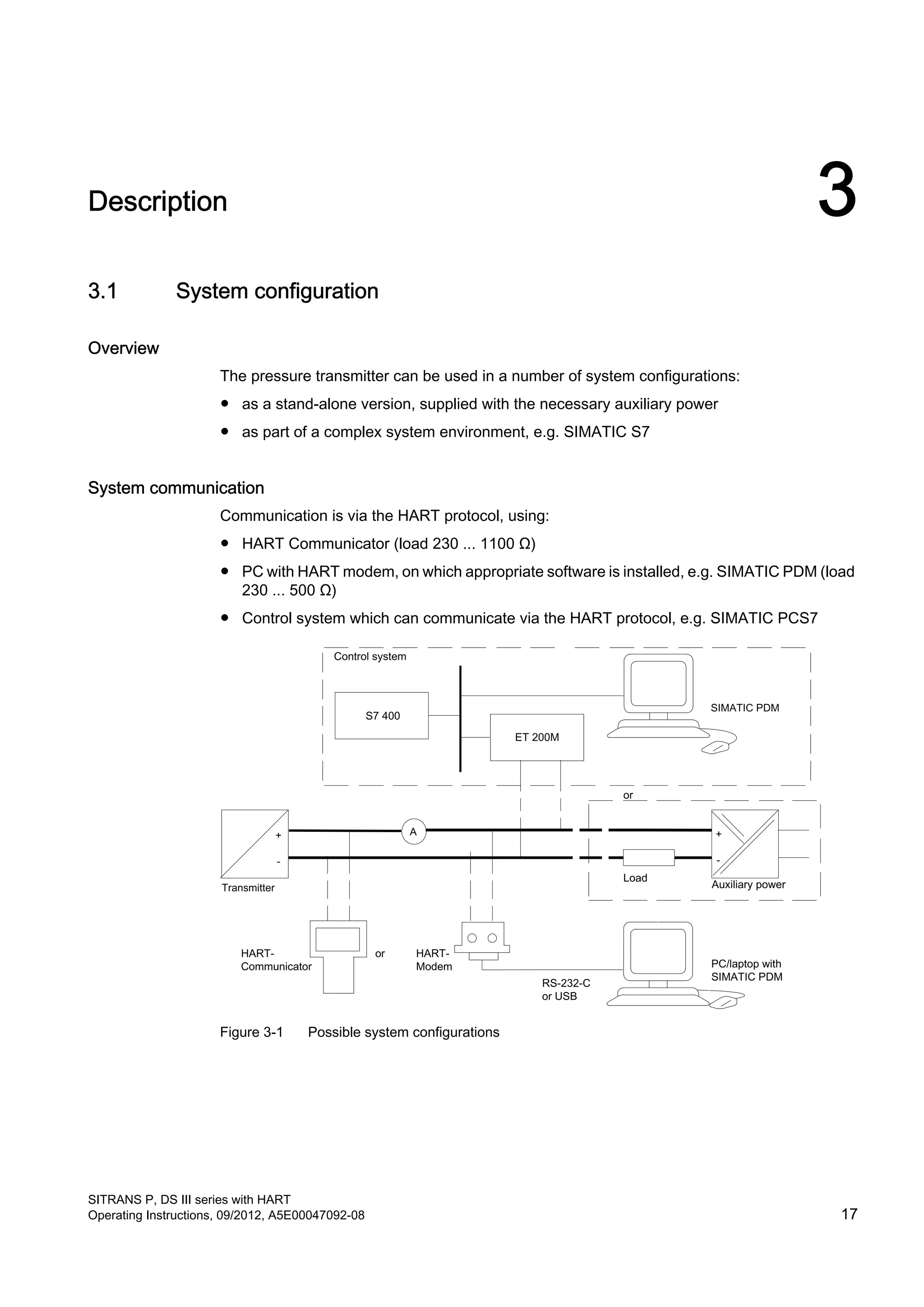
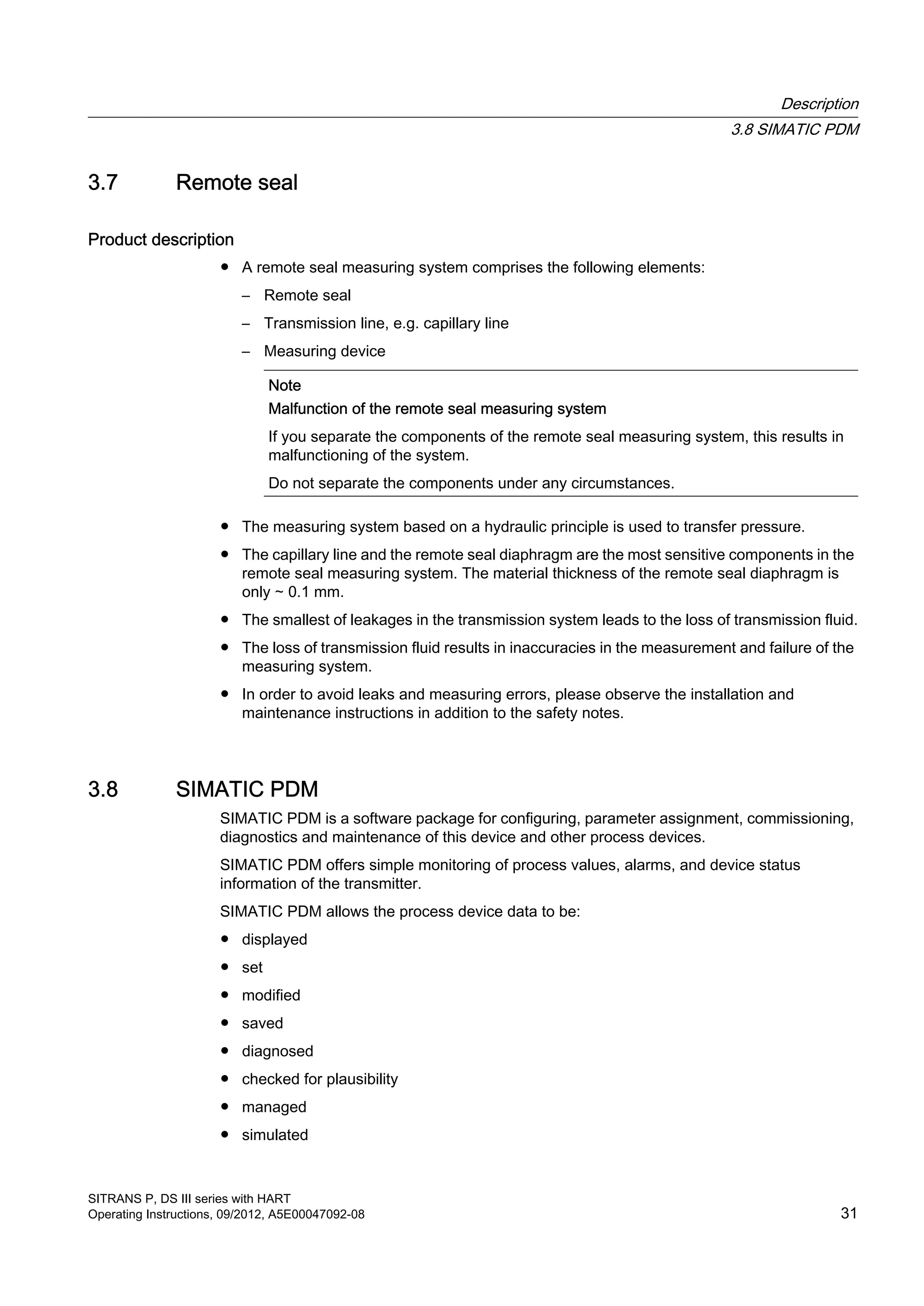
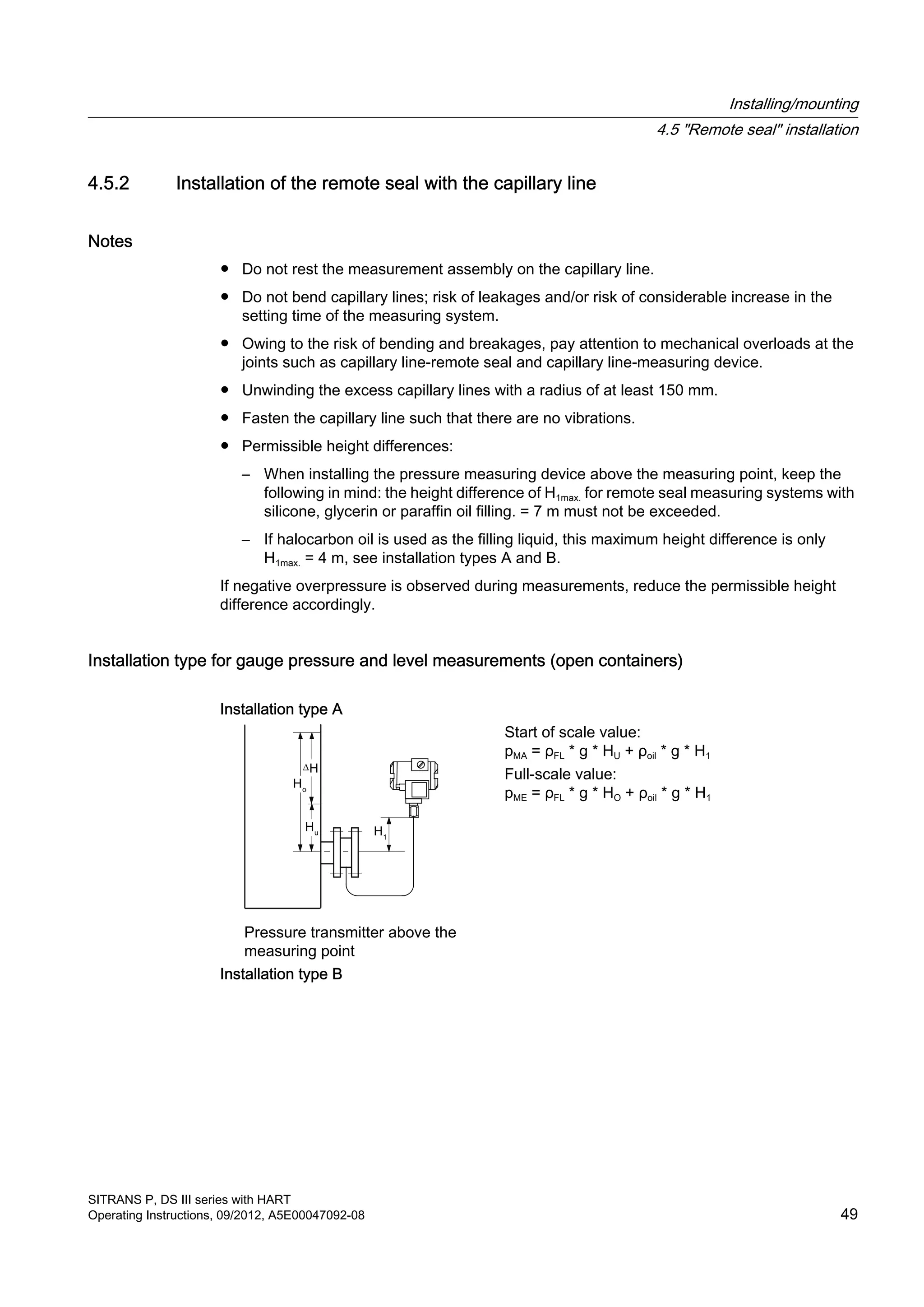
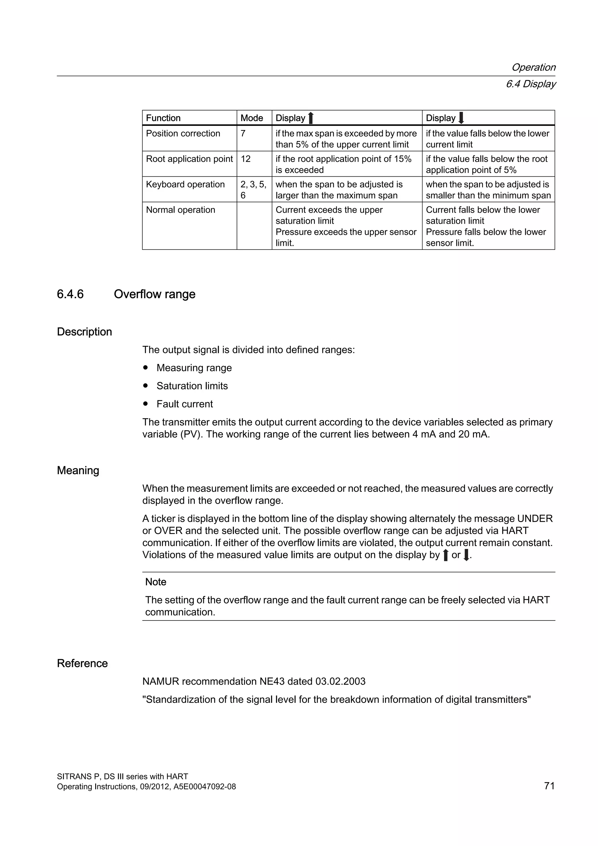
![Procedure
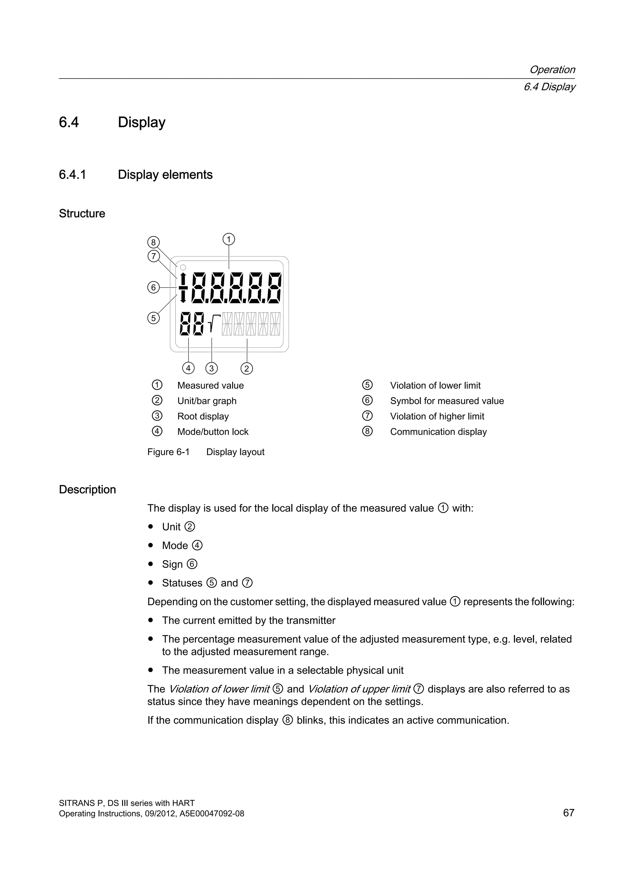
In the default setting, the device is in the measured value display.
To adjust the operating functions, proceed as follows:
1. Loosen both the screws of the keyboard cover and lift it upwards.
2. Keep pressing the [M] button until the desired mode is displayed.
3. Keep pressing the [↑] or [↓] button until the desired value is displayed.
4. Press the [M] button.
Now you have saved the values and the device goes to the next mode.
5. Close the keyboard cover using the two screws.
Note
The setting is saved and the measured values are automatically displayed again if more
than two minutes have passed after a button was pressed for the last time.
See also
Releasing key lock or function lock (Page 91)
6.5.3 Start of scale value/full scale value
6.5.3.1 Difference between setting and adjusting
Introduction
In "Pressure" measuring mode, you can set or adjust the start of scale value and full scale
value using the buttons. Modes 2 and 3 are used for this. Rising and falling characteristic
curves can be realized with appropriate use of the buttons. If the transmitter is not in "Pressure"
measuring mode, this mode is skipped in local operation.
Difference
The difference between setting and adjusting lies in the calculation.
Setting with reference pressure
Condition
Two reference pressures pr1 and pr2 are available. The reference pressures are initialized by
the process or generated by a pressure sensor.
When setting, a desired start of scale value or a full scale value is allocated to the standard
current values (4 mA or 20 mA). After setting, the span given on the nameplate may no longer
correspond to the setting.
Operation
6.5 Local operation
SITRANS P, DS III series with HART
Operating Instructions, 09/2012, A5E00047092-08 75](https://image.slidesharecdn.com/a5e00047092-07ends3hartexoien-us-150107073133-conversion-gate02/75/Manual-trm-siemens-77-2048.jpg)
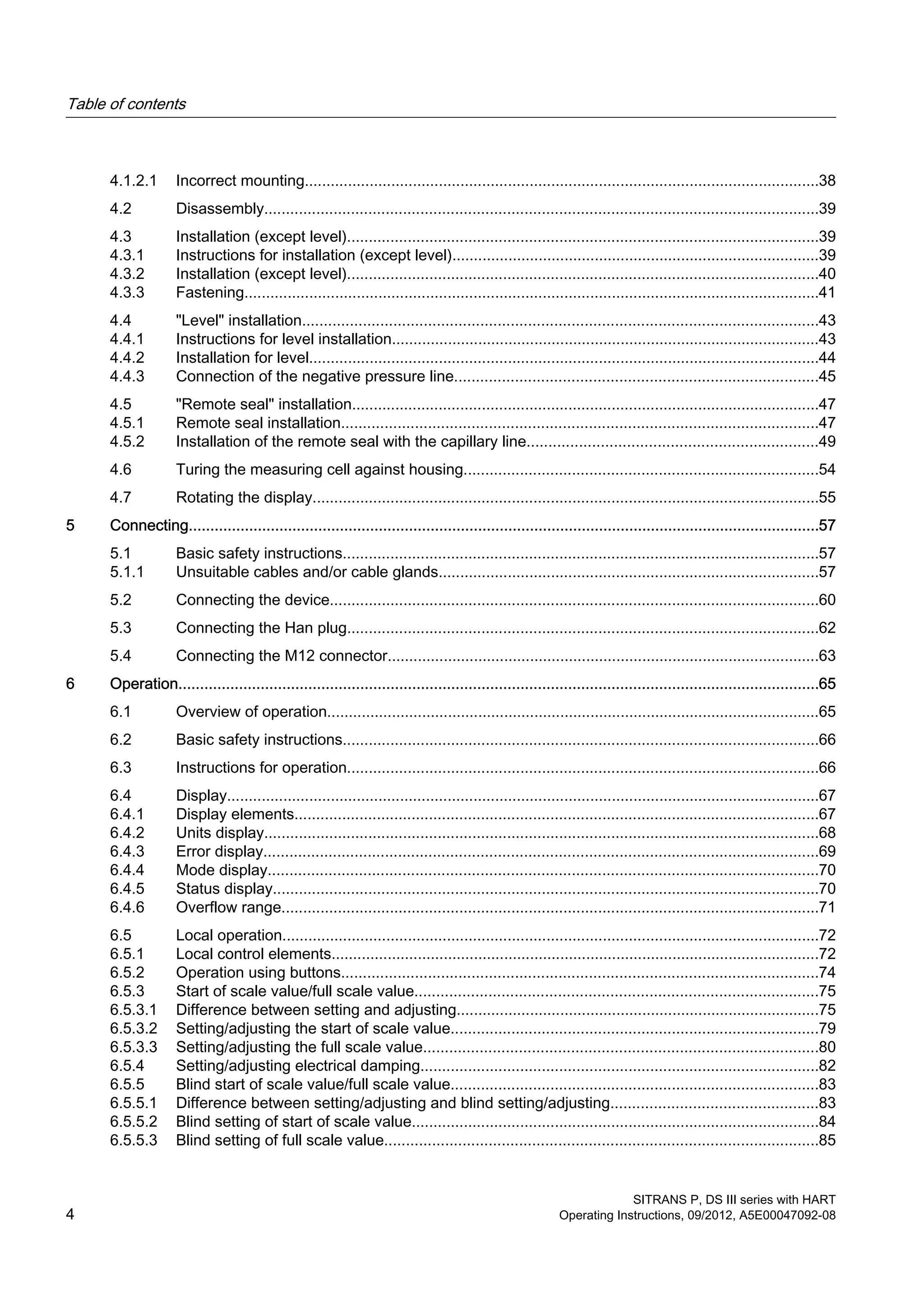
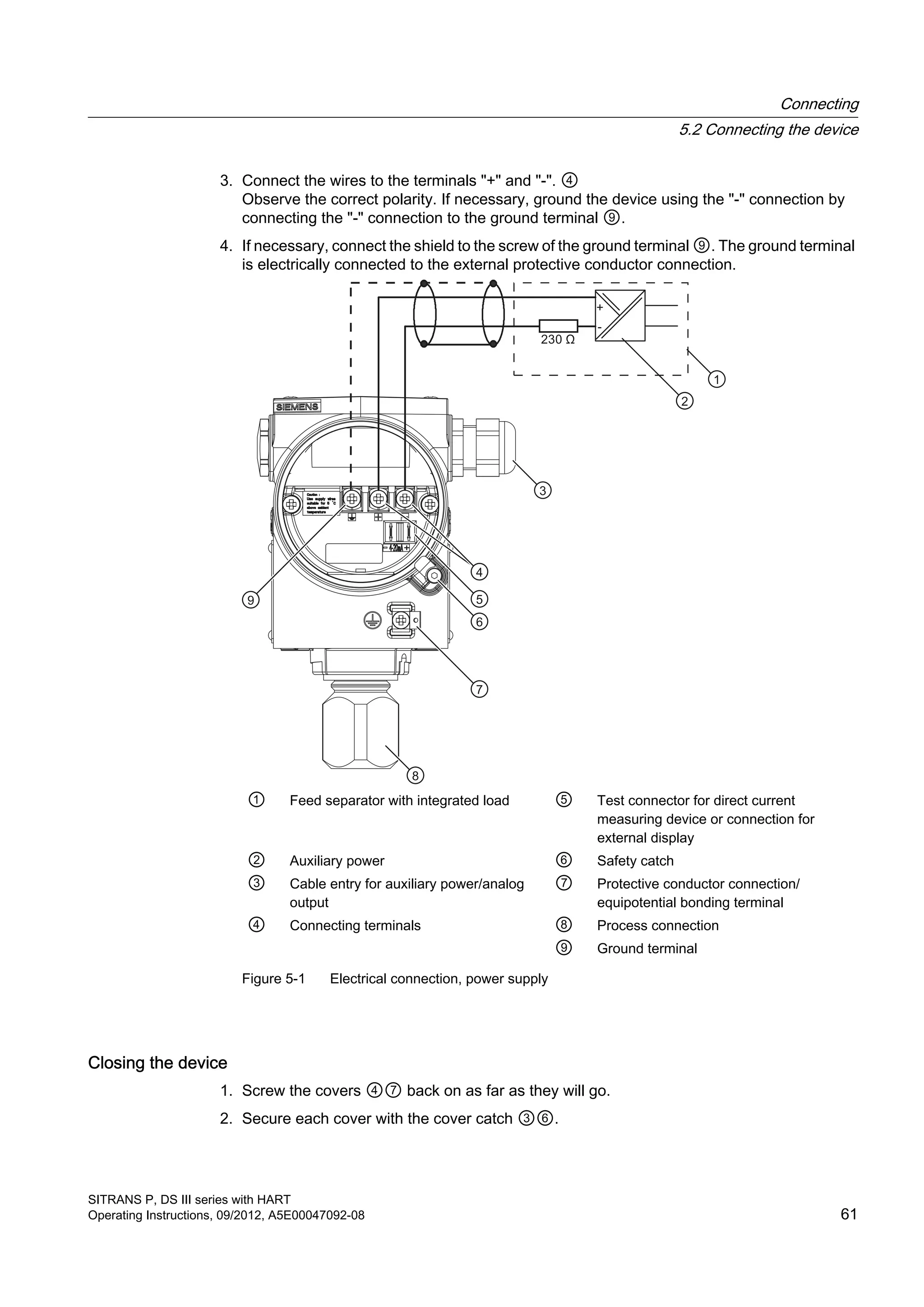
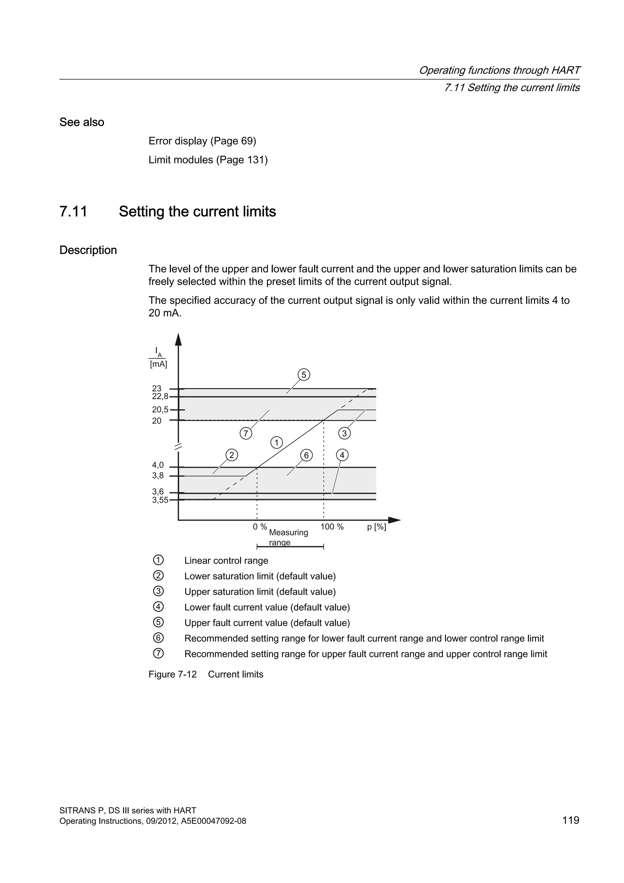
![Depending on the series and measuring range, a maximum downscaling of 1:100 can be
achieved (measuring span ratio = r, turn down).
The correlation between the measured pressure and the output current generated is linear.
The square root extracting characteristic curve for differential pressure transmitters is an
exception. Calculate the output current using the following formula.
I Output current MAactual Old start of scale value
p Pressure MEactual Old full scale value
MA Start of scale value MAtarget New start of scale value
ME Full scale value MEtarget New full scale value
Figure 6-6 Current calculation formula for setting
Example of setting with reference pressure
A Initial situation
B Setting start of scale value
C Setting full scale value
Explanations for the example of setting with reference pressure
A The measuring range is from 0 to 16 bar. You are changing the start of scale value from 0
to 2 bar and the full scale value from 16 to 14 bar. The measuring span is then 12 bar.
B 2 bar process pressure is created.
Use the [M] button to set the transmitter to mode 2. To set the start of scale value, press
the [↑] and [↓] buttons simultaneously for 2 seconds.
If there is 2 bar input pressure, the transmitter produces an output current of 4 mA.
Operation
6.5 Local operation
SITRANS P, DS III series with HART
76 Operating Instructions, 09/2012, A5E00047092-08](https://image.slidesharecdn.com/a5e00047092-07ends3hartexoien-us-150107073133-conversion-gate02/75/Manual-trm-siemens-78-2048.jpg)
![C 14 bar process pressure is created.
Use the [M] button to set the transmitter to mode 3. To set the full scale value, press the
[↑] and [↓] buttons simultaneously for 2 seconds.
If there is 14 bar input pressure, the transmitter produces an output current of 20 mA.
D The output current can be calculated for any input pressure using the "current calculation
formula for setting".
Note
If the value exceeds or falls below the preset measuring limits by more than 20% when setting,
the setting function is not carried out. The old value is retained in this case.
With a marked elevation of the zero point, the full scale value must therefore previously be
reduced such that it still lies within the permitted range after elevation of the zero point. This
setting function is only possible in "Pressure" measuring mode.
Adjusting with reference pressure
Condition:
The reference pressure, the adjusted start of scale value and adjusted full scale value are
known.
When adjusting, a start of scale value or a full scale value can be allocated to a desired current
value with the aid of a reference pressure. This function is particularly suitable when the
required pressures for the start of scale value and the full scale value are not available After
adjustment, the measuring range specified on the nameplate may no longer correspond to the
setting made.
Using the formulae below, the current to be set for the desired start of scale value and the full
scale value can be calculated.
To calculate the output currents when setting the start of scale value or the full scale value,
the reference pressure must be selected such that a value between 4 and 20 mA results for
the current.
I Output current MAactual Old start of scale value
IMA Current to be adjusted with MAtarget MEactual Old full scale value
IME Current to be adjusted with MEtarget MAtarget New start of scale value
p Pressure MEtarget New full scale value
pref Existing reference pressure
Figure 6-7 Current calculation formula for setting with reference pressure
Operation
6.5 Local operation
SITRANS P, DS III series with HART
Operating Instructions, 09/2012, A5E00047092-08 77](https://image.slidesharecdn.com/a5e00047092-07ends3hartexoien-us-150107073133-conversion-gate02/75/Manual-trm-siemens-79-2048.jpg)
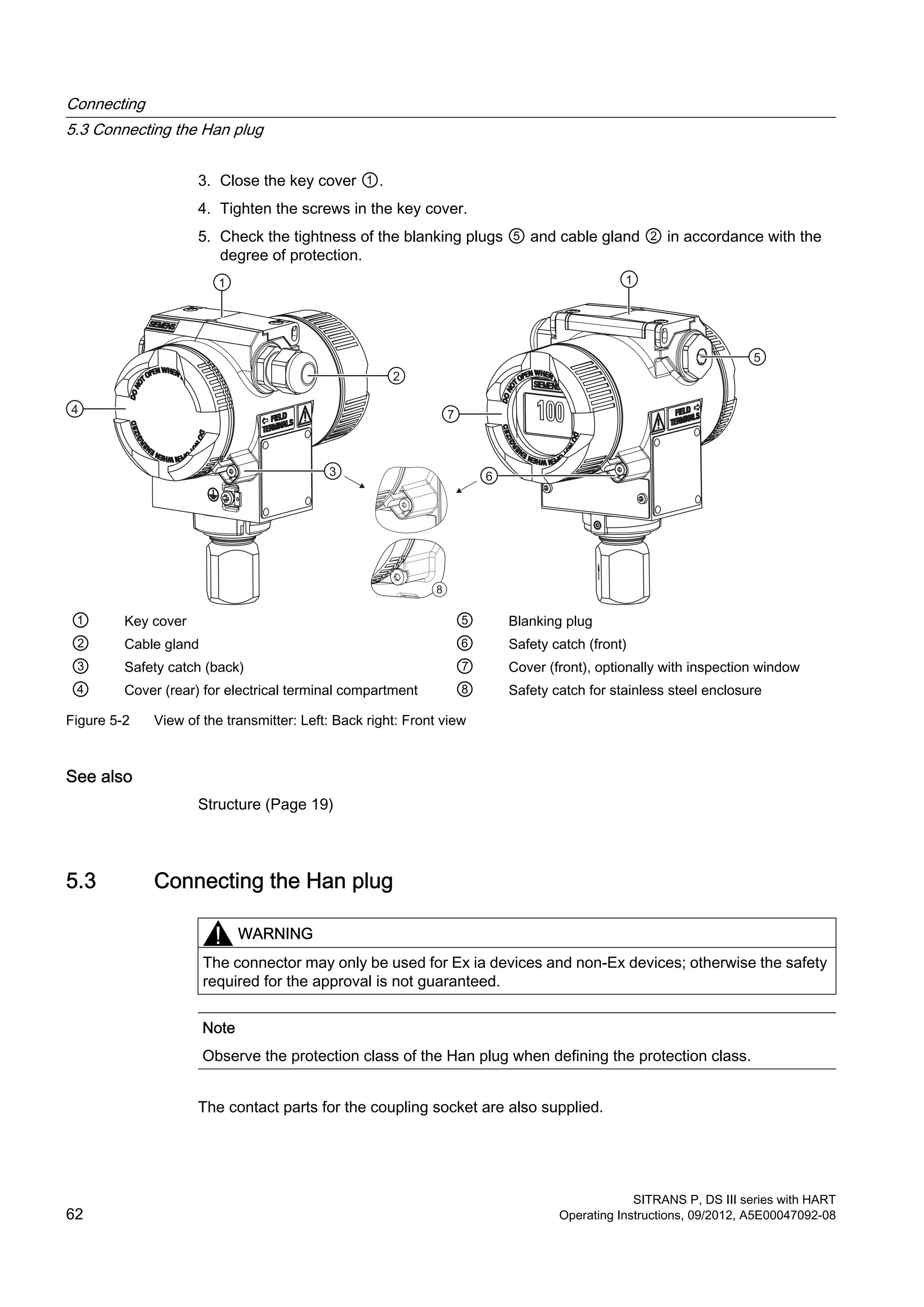
![Example of adjusting with reference pressure
A Initial situation
B Calculating start of scale value
C Calculating full scale value
Explanations for the example of adjusting with reference pressure
A The measuring range is from 0 to 16 bar. You are changing the start of scale value from 0
to 2 bar and the full scale value from 16 to 14 bar. The measuring span is then 12 bar.
A reference pressure of 11 bar is created.
B Use the [M] button to set the transmitter to mode 2.
The "Current calculation formula for adjusting with reference pressure" can be used to
calculate the current to be adjusted for the desired start of scale value IMA (13 mA at 2 bar)
with the existing reference pressure. It can be adjusted with the [↑] or [↓] buttons IMA.
C Use the [M] button to set the transmitter to mode 3.
The "Current calculation formula for adjusting" can be used to calculate the current to be
adjusted for the desired full scale value IME (16 mA at 14 bar) with the existing reference
pressure. It can be adjusted with the [↑] or [↓] buttons IM.
Note
If the preset measuring limits are exceeded or fallen below by more than 20% during
adjustment, the resulting current cannot be set above these limits.
With a marked elevation of the zero point, the full scale value must therefore previously be
reduced such that it still lies within the permitted range after elevation of the zero point.
See also
Unit (Page 95)
Operation
6.5 Local operation
SITRANS P, DS III series with HART
78 Operating Instructions, 09/2012, A5E00047092-08](https://image.slidesharecdn.com/a5e00047092-07ends3hartexoien-us-150107073133-conversion-gate02/75/Manual-trm-siemens-80-2048.jpg)
![6.5.3.2 Setting/adjusting the start of scale value
NOTICE
Inadvertent adjustment of parameters on devices without display or without visible display
Key lock is canceled if you press the [M] key for longer than 5 seconds, see chapter
"Releasing key lock or function lock (Page 91)". In the case of a device without display or
without a visible display, you could inadvertently change parameters.
● Always press the [M] key for less than 5 seconds.
Introduction
Set or adjust the start of scale value of the pressure transmitter in mode 2.
You can also adjust the start of scale value or the full scale value separately as well as adjust
both these values one after the other.
Condition
You are familiar with the correct operation of the transmitter and the associated safety notes.
You have selected a reference pressure that corresponds to the start of scale value and is
within the permissible tolerance range.
The transmitter is in "Pressure" measuring mode.
Setting start of scale value
To set the output current of the start of scale value to 4 mA, proceed as follows:
1. Create the reference pressure.
2. Set mode 2.
3. Set the start of scale value to 4 mA.
4. Save with the [M] button.
Adjusting start of scale value
If you do not set the output current but constantly adjust it, you need to calculate the currents
to be adjusted mathematically.
To the adjust the output current of the start of scale value, proceed as follows:
1. Create the reference pressure.
2. Set mode 2.
3. Adjust the output current of the start of scale value to the calculated value.
4. Save with the [M] button.
Operation
6.5 Local operation
SITRANS P, DS III series with HART
Operating Instructions, 09/2012, A5E00047092-08 79](https://image.slidesharecdn.com/a5e00047092-07ends3hartexoien-us-150107073133-conversion-gate02/75/Manual-trm-siemens-81-2048.jpg)
![Setting the start-of-scale value without a display
You have a device with a cover that does not have an inspection window and you wish to set
the start of scale value.
To set the output current of the start of scale value to 4 mA, proceed as follows:
1. Create the reference pressure.
2. Press the [↑] and [↓] buttons simultaneously.
The device has set the start of scale value to 4 mA.
3. When you release the buttons, the device saves the adjusted value automatically.
Setting the start-of-scale value without a display
You have a device with a cover that does not have an inspection window and you do not wish
to set the start of scale value, but adjust it.
You will need an ammeter for this purpose.
To the adjust the output current of the start of scale value, proceed as follows:
1. Connect the ammeter to the test connector.
2. Create the reference pressure.
3. Adjust the output current of the start of scale value using the [↑] or [↓] button.
4. When you release the button, the device saves the adjusted value automatically.
6.5.3.3 Setting/adjusting the full scale value
Introduction
Set or adjust the full scale value of the pressure transmitter in mode 3.
You can also adjust the start of scale value or the full scale value separately as well as adjust
both these values one after the other.
Condition
You are familiar with the correct operation of the transmitter and the associated safety notes.
You have selected a reference pressure that corresponds to the full scale value and is within
the permissible tolerance range.
The transmitter is in "Pressure" measuring mode.
Setting full scale value
To set the output current of the full scale value to 20 mA, proceed as follows:
1. Create the reference pressure.
2. Set mode 3.
Operation
6.5 Local operation
SITRANS P, DS III series with HART
80 Operating Instructions, 09/2012, A5E00047092-08](https://image.slidesharecdn.com/a5e00047092-07ends3hartexoien-us-150107073133-conversion-gate02/75/Manual-trm-siemens-82-2048.jpg)
![3. Set the full scale value to 20 mA.
4. Save with the [M] button.
Adjusting full scale value
If you do not set the output current but constantly adjust it, you need to calculate the currents
to be adjusted mathematically.
To the adjust the output current of the full scale value, proceed as follows:
1. Create the reference pressure.
2. Set mode 3.
3. Adjust the output current of the full scale value to the calculated value.
4. Save with the [M] button.
Setting the full-scale value without a display
You have a device with a cover that does not have an inspection window and you wish to set
the full scale value.
To set the output current of the full scale value to 20 mA, proceed as follows:
1. Create the reference pressure.
2. Press and hold the [M] button.
3. Also press the [↑] and [↓] buttons simultaneously.
The device has set the full scale value to 20 mA.
4. When you release the buttons, the device saves the adjusted value automatically.
Setting the full-scale value without a display
You have a device with a cover that does not have an inspection window and you do not wish
to set the full scale value, but adjust it continuously.
You will need an ammeter for this purpose.
To the adjust the output current of the full scale value, proceed as follows:
1. Connect the ammeter to the test connector.
2. Create the reference pressure.
3. Press and hold the [M] button.
4. Adjust the output current of the full scale value to the calculated value using the [↑] or [↓]
button.
5. When you release the button, the device saves the adjusted value automatically.
Operation
6.5 Local operation
SITRANS P, DS III series with HART
Operating Instructions, 09/2012, A5E00047092-08 81](https://image.slidesharecdn.com/a5e00047092-07ends3hartexoien-us-150107073133-conversion-gate02/75/Manual-trm-siemens-83-2048.jpg)
![6.5.4 Setting/adjusting electrical damping
Difference between setting and adjusting
You can set or adjust the time constant of electrical damping using the buttons. Setting means
that the time constant is automatically set to 0 seconds. Adjusting means that the time constant
is adjusted between 0 and 100 seconds using the steps of 0.1 seconds. This electrical damping
also has an effect on the built-in basic damping of the device.
Condition for "setting"
You are familiar with the correct operation of the transmitter and the associated safety notes.
Setting electrical damping
To set electrical damping to 0 seconds, proceed as follows:
1. Set mode 4.
2. Press the [↑] and [↓] buttons simultaneously.
3. Save with the [M] button.
Result
Electrical damping has been set to 0 seconds.
Condition for "adjusting"
The default setting of steps is an interval of 0.1 seconds. If you press the [↑] or [↓] button for
a longer time, the step is increased.
Adjusting electrical damping
To adjust electrical damping, proceed as follows:
1. Set mode 4.
2. Adjust the desired damping.
3. Save with the [M] button.
Result
Electrical damping has been set to the desired time constant.
Operation
6.5 Local operation
SITRANS P, DS III series with HART
82 Operating Instructions, 09/2012, A5E00047092-08](https://image.slidesharecdn.com/a5e00047092-07ends3hartexoien-us-150107073133-conversion-gate02/75/Manual-trm-siemens-84-2048.jpg)
![6.5.5 Blind start of scale value/full scale value
6.5.5.1 Difference between setting/adjusting and blind setting/adjusting
Differences
In contrast to setting/adjusting with a reference pressure, you do not need a reference pressure
for blind setting/adjusting. You can adjust a value in the physical variable "pressure" without
a reference pressure, and an output current with a reference pressure.
Blind adjusting
First select the desired physical unit. Then, adjust two pressure values using the [↑] and [↓]
buttons and save them in the device. These theoretical pressure values are allocated to the
standard current values 4 mA and 20 mA.
Depending on the series and measuring range, a maximum downscaling of 1:100 can be
achieved (measuring span ratio = r, turn down).
The correlation between the measured pressure and the output current generated is linear.
The square root extracting characteristic curve for differential pressure transmitters is an
exception.
Example of blind adjusting
A Initial situation
B Blind adjustment of the start of
scale value
C Blind adjustment of the full
scale value
I Output current p Pressure
MAactua
l
Old start of scale value MAtarget New start of scale value
MEactua
l
Old full scale value MEtarget New full scale value
Operation
6.5 Local operation
SITRANS P, DS III series with HART
Operating Instructions, 09/2012, A5E00047092-08 83](https://image.slidesharecdn.com/a5e00047092-07ends3hartexoien-us-150107073133-conversion-gate02/75/Manual-trm-siemens-85-2048.jpg)
![Explanations for the blind adjusting example
A The measuring range is from 0 to 16 bar. You are changing the start of scale value from 0
to 2 bar and the full scale value from 16 to 14 bar. The measuring span is then 12 bar.
In this example you create no pressure.
B Use the [M] button to switch the transmitter to mode 5. To adjust the start of scale value
to 2 bar, press one of the [↑] or [↓] buttons.
If there is 2 bar input pressure, the transmitter produces an output current of 4 mA.
C Use the [M] button to switch the transmitter to mode 6. To adjust the full scale value to
14 bar, press one of the [↑] or [↓] buttons.
If there is 14 bar input pressure, the transmitter produces an output current of 20 mA.
Note
If the preset measuring limits are exceeded or fallen below by more than 20% during
adjustment, the resulting current cannot be set above these limits.
With a marked elevation of the zero point, the full scale value must therefore previously be
reduced such that it still lies within the permitted range after elevation of the zero point.
Setting without reference pressure
Blind setting resets the start of scale value to the lower sensor limit and the full scale value to
the upper sensor limit.
Note
If the value exceeds or falls below the preset measuring limits by more than 20% when setting,
the setting function is not carried out. The old value is retained in this case.
With a marked elevation of the zero point, the full scale value must therefore previously be
reduced such that it still lies within the permitted range after elevation of the zero point.
6.5.5.2 Blind setting of start of scale value
Introduction
Blind setting resets the start of scale value to the lower sensor limit.
Note
Changes in modes 5 and 6 have an exclusive effect on pressure scaling. This does not affect
the scaling for level or customized characteristic curve. Therefore, only measured pressure
values and pressure units are displayed in these modes.
Operation
6.5 Local operation
SITRANS P, DS III series with HART
84 Operating Instructions, 09/2012, A5E00047092-08](https://image.slidesharecdn.com/a5e00047092-07ends3hartexoien-us-150107073133-conversion-gate02/75/Manual-trm-siemens-86-2048.jpg)
![Condition
You are familiar with the correct operation of the transmitter and the associated safety notes.
You have not created any reference pressure and have selected a pressure unit.
Procedure
To the set the start of scale value blindly, proceed as follows:
1. Set mode 5.
2. Press the [↑] and [↓] buttons simultaneously for 2 seconds.
6.5.5.3 Blind setting of full scale value
Introduction
Blind setting resets the full scale value to the upper sensor limit.
Note
Changes in modes 5 and 6 have an exclusive effect on pressure scaling. This does not affect
the scaling for level or customized characteristic curve. Therefore, only measured pressure
values and pressure units are displayed in these modes.
Condition
You are familiar with the correct operation of the transmitter and the associated safety notes.
You have not created any reference pressure and have selected a pressure unit.
Procedure
To the set the full scale value blindly, proceed as follows:
1. Set mode 6.
2. Press the [↑] and [↓] buttons simultaneously for 2 seconds.
Operation
6.5 Local operation
SITRANS P, DS III series with HART
Operating Instructions, 09/2012, A5E00047092-08 85](https://image.slidesharecdn.com/a5e00047092-07ends3hartexoien-us-150107073133-conversion-gate02/75/Manual-trm-siemens-87-2048.jpg)
![6.5.5.4 Blind adjusting of the start of scale value
Introduction
In the case of blind adjustment, adjust the pressure value of the start of scale value
continuously and without a reference pressure.
Note
Changes in modes 5 and 6 have an exclusive effect on pressure scaling. This does not affect
the scaling for level or customized characteristic curve. Therefore, only measured pressure
values and pressure units are displayed in these modes.
You can toggle between rising and falling characteristic curves.
Condition
You are familiar with the correct operation of the transmitter and the associated safety notes.
You have not created any reference pressure and have selected a pressure unit.
Procedure
To the adjust the pressure value of the start of scale value blindly, proceed as follows:
1. Set mode 5.
2. Adjust the pressure value of the start of scale value.
3. Save with the [M] button.
6.5.5.5 Blind adjustment of the full scale value
Introduction
In the case of blind adjustment, adjust the pressure value of the full scale value continuously
and without a reference pressure.
Note
Changes in modes 5 and 6 have an exclusive effect on pressure scaling. This does not affect
the scaling for level or customized characteristic curve. Therefore, only measured pressure
values and pressure units are displayed in these modes.
You can toggle between rising and falling characteristic curves by swapping the start of scale
value and the full scale value.
Operation
6.5 Local operation
SITRANS P, DS III series with HART
86 Operating Instructions, 09/2012, A5E00047092-08](https://image.slidesharecdn.com/a5e00047092-07ends3hartexoien-us-150107073133-conversion-gate02/75/Manual-trm-siemens-88-2048.jpg)
![Condition
You are familiar with the correct operation of the transmitter and the associated safety notes.
You have not created any reference pressure and have selected a pressure unit.
Procedure
To the adjust the pressure value of the full scale value blindly, proceed as follows:
1. Set mode 6.
2. Adjust the pressure value of the full scale value.
3. Save with the [M] button.
6.5.6 Trimming the zero point
Introduction
The zero point is calibrated in mode 7. Zero point calibration corrects zero point errors resulting
from the installation position of the pressure transmitter. The device type determines the way
in which you proceed.
SIMATIC PDM or the HART communicator will display the total of all zero point corrections.
Condition
You are familiar with the correct operation of the transmitter and the associated safety notes.
Zero point calibration for gauge pressure transmitter
To calibrate the zero point, proceed as follows:
1. Pressurize the transmitter.
2. Set mode 7.
3. Press the [↑] and [↓] keys simultaneously for 2 seconds.
4. Save using the [M] key.
Zero point calibration for absolute pressure transmitter
Note
You need a reference pressure known to you which lies within the measuring limits.
To calibrate the zero point, proceed as follows:
Operation
6.5 Local operation
SITRANS P, DS III series with HART
Operating Instructions, 09/2012, A5E00047092-08 87](https://image.slidesharecdn.com/a5e00047092-07ends3hartexoien-us-150107073133-conversion-gate02/75/Manual-trm-siemens-89-2048.jpg)
![1. Create the reference pressure.
2. Set mode 7.
3. Set the reference pressure on the display.
4. Save using the [M] key.
6.5.7 Current transmitter
Introduction
In mode 8, switch the pressure transmitter into the constant current operation. You can connect
an external current transmitter in the constant current operation. The current then no longer
corresponds to the process variable. The following output current can be adjusted irrespective
of the input pressure:
● 3.6 mA
● 4.0 mA
● 12.0 mA
● 20.0 mA
● 22.8 mA
You can use HART communication to adjust intermediate values.
Procedure
To switch on the constant current operation, proceed as follows:
1. Set mode 8.
"Cur" in the display stands for current.
2. Press the [↑] and [↓] buttons simultaneously.
3. Select constant current.
Switching off the constant current operation
To switch off the constant current operation, proceed as follows:
Press the [M] button in mode 8.
Operation
6.5 Local operation
SITRANS P, DS III series with HART
88 Operating Instructions, 09/2012, A5E00047092-08](https://image.slidesharecdn.com/a5e00047092-07ends3hartexoien-us-150107073133-conversion-gate02/75/Manual-trm-siemens-90-2048.jpg)
![6.5.8 Output current in case of fault
Introduction
When a fault occurs, the upper fault current is displayed in the basic setting. In mode 9, you
can choose between the output of the upper and lower fault current. The standard values
3.6 mA and 22.8 mA are set.
The standard values of the upper and lower fault current can be changed via HART
communication.
Condition
You are familiar with the correct operation of the transmitter and the associated safety notes.
Procedure
To change the fault current, proceed as follows:
1. Set mode 9.
2. Select the fault current.
3. Save using the [M] key.
Note
If a current saturation interrupt is active, the setting of the output current may deviate from
your setting in the case of a fault.
Resetting fault current
To reset the fault current to the basic setting, proceed as follows:
Press the [↑] and [↓] [M] keys simultaneously.
Fault causes
Fault currents may be triggered by:
● FW alarm
● HW alarm
● Diagnostic interrupt
● Sensor breakage
● Measured value status BAD
Reference
NAMUR recommendation NE43 dated 02/03/2003
"Standardization of the signal level for the breakdown information of digital transmitters"
Operation
6.5 Local operation
SITRANS P, DS III series with HART
Operating Instructions, 09/2012, A5E00047092-08 89](https://image.slidesharecdn.com/a5e00047092-07ends3hartexoien-us-150107073133-conversion-gate02/75/Manual-trm-siemens-91-2048.jpg)
![6.5.9 buttons and function lock
Introduction
In mode 10, you can disable the functions that can be executed using buttons. Application
example for a lock is e.g. safeguarding the saved parameters.
Lock options
You have the following lock options on the pressure transmitter:
Table 6-5 Meaning of lock modes
Lock mode Meaning
0 The device can be operated by means of the keys and HART communication.
LA Keys on the transmitter are locked.
Exception:
● Releasing key lock
The device can be operated by means of HART communication.
LO Keys on the transmitter are partially locked.
Exception:
● Setting start of scale value
● Releasing key lock
The device can be operated by means of HART communication.
LS Keys on the transmitter are partially locked.
Exception:
● Setting start of scale value
● Setting full scale value
● Releasing key lock
The device can be operated by means of HART communication.
L Write protection
Operation via keys and HART communication is blocked.
Exception:
● Releasing key lock
Note
If you want to select the LO or LS lock, we recommend you first select the measured value
display of "Current" in "mA" or "%" in mode 13. Otherwise, a change in the output variable
using the [↑] and [↓] buttons is not detected.
If the blind cover is provided, the LS lock mode is effective, i.e. only the zero point and the
span can be changed. If you continuously operate the device with the blind cover, ensure
that the LS lock mode is constantly set.
Operation
6.5 Local operation
SITRANS P, DS III series with HART
90 Operating Instructions, 09/2012, A5E00047092-08](https://image.slidesharecdn.com/a5e00047092-07ends3hartexoien-us-150107073133-conversion-gate02/75/Manual-trm-siemens-92-2048.jpg)
![Condition
You are familiar with the correct operation of the transmitter and the associated safety notes.
Note
In the measured value display function, check whether the desired setting is displayed.
Procedure
To disable the buttons, proceed as follows:
1. Set mode 10.
2. Select the desired lock mode.
3. Confirm the lock mode with the [M] button.
6.5.10 Releasing key lock or function lock
Releasing key lock
WARNING
In the case of devices used for safety-relevant applications, only authorized personnel may
release the key lock, e.g. overflow protection.
To release a set key lock (LA, LO, LS) using buttons, proceed as follows:
Press the [M] button for 5 seconds.
Releasing the write protection
To release a write protection for HART (L) using buttons, proceed as follows:
Press the [M] button for 5 seconds.
6.5.11 Flow rate measurement (only differential pressure)
Introduction
The characteristic curve representing the relationship between the output current and input
pressure can be adjusted in mode 11. Adjust the root application point in mode 12.
You can select the following characteristic curve types of the output current:
Operation
6.5 Local operation
SITRANS P, DS III series with HART
Operating Instructions, 09/2012, A5E00047092-08 91](https://image.slidesharecdn.com/a5e00047092-07ends3hartexoien-us-150107073133-conversion-gate02/75/Manual-trm-siemens-93-2048.jpg)
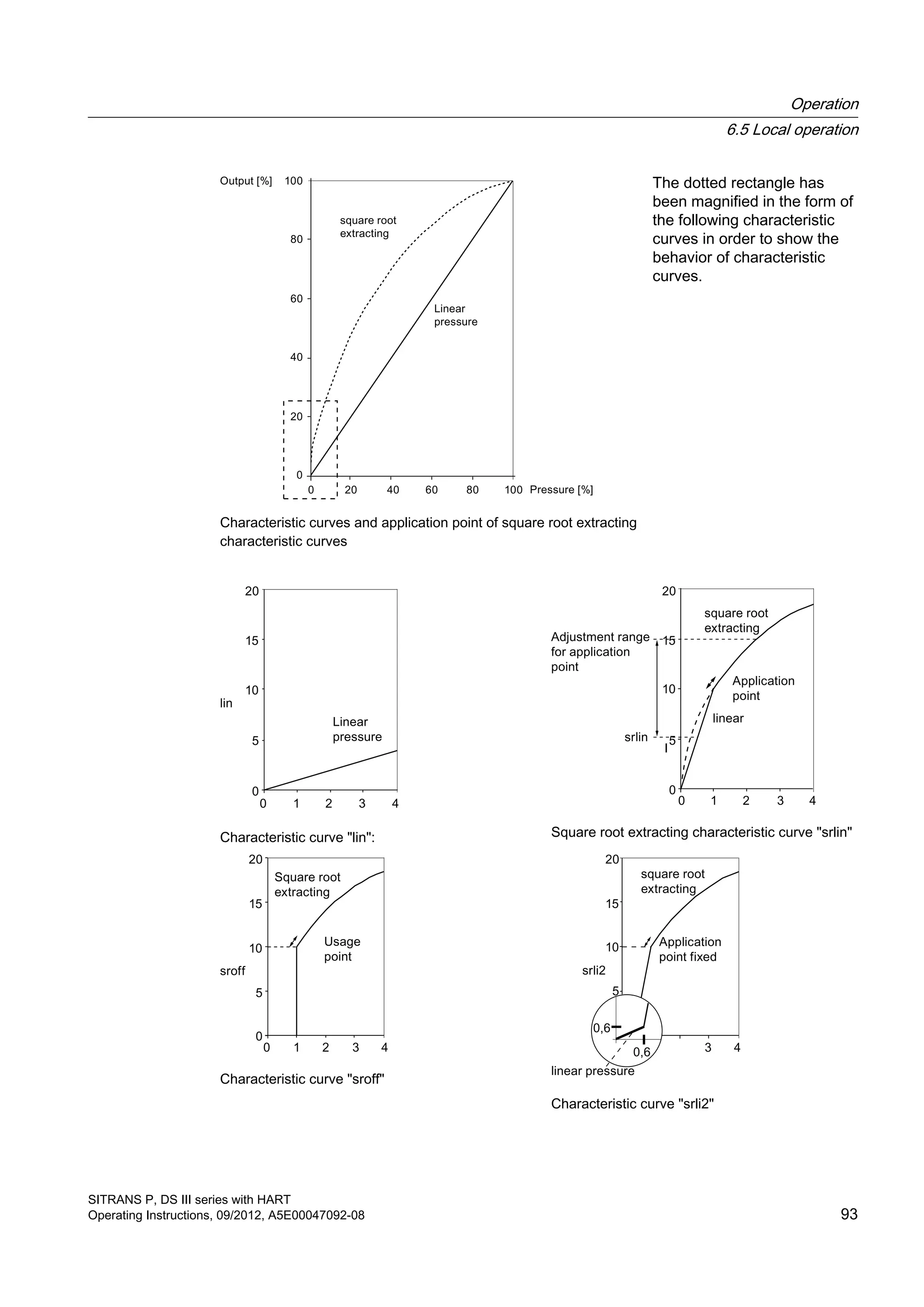
![● linear "lin": proportional to differential pressure
● square root extracting "sroff": proportional to flow rate, deactivated up to the application
point
● square root extracting "srlin": proportional to flow rate, linear up to the application point
● square root extracting "srli2": proportional to flow rate, two-step linear up to the application
point
Variable application point
The output current for the "srlin" and "sroff" functions can be displayed linearly or set to zero
below the application point of the square root extracting characteristic curve.
Fixed application point
The "srli2" function has a permanently defined application point of 10%. The range up to this
point contains two linear characteristic curve sections. The first section ranges from the zero
point to 0.6% of the output value and 0.6% of the pressure value. The second section has a
higher gradient and it goes up to the root application point at 10% of the output value and 1%
of the pressure value. See the following figure for this purpose.
Procedure
Proceed as follows to set or adjust the type of characteristic curve:
1. Set mode 11.
2. Select the type of characteristic curve.
To set the characteristic curve to "linear", press the [↑] and [↓] buttons simultaneously.
3. Save with the [M] button.
Proceed as follows to set or adjust the root application point: This procedure is not applicable
for "srli2":
1. Set mode 12.
2. Select an application point between 5 and 15%.
To set the application point to 10%, press the [↑] and [↓] buttons simultaneously.
3. Save with the [M] button.
Note
Mode 12 cannot be selected if the "linear" or "srli2" measuring mode has been adjusted
in mode 11.
If the square root extracting characteristic curve has been adjusted in mode 11 and if the
measured value display has been set to "Pressure" in mode 13, the root sign and the
differential pressure corresponding to the flow rate are displayed.
The "srli2" square root extraction function is set as default in "Flow rate" measuring mode.
Operation
6.5 Local operation
SITRANS P, DS III series with HART
92 Operating Instructions, 09/2012, A5E00047092-08](https://image.slidesharecdn.com/a5e00047092-07ends3hartexoien-us-150107073133-conversion-gate02/75/Manual-trm-siemens-94-2048.jpg)
![6.5.12 Measured value display
Note
To use the operating functions with the buttons, first set the device variable (DV) parameters
with a host system such as SIMATIC PDM. You will finds details of the relation between
primary variable (PV) assignment and the DV in the following section:
Measuring mode "Pressure" (Page 101)
Introduction
In mode 13, adjust the following types of measured value display:
● mA
● %
● Display of the PV selected via HART. (Default setting: P pressure)
Table 6-6 Display of measuring mode/device variables
Display DV Meaning
P 0 Pressure
t-SE 1 Sensor temperature
t-EL 2 Electronics temperature
P-UNC 3 Pressure (untrimmed)
LEVEL 4 Level
Vol 5 Volume
MASS 6 Mass
V-Flo 7 Volumetric flow rate (not relevant for gauge or absolute pressure)
M-Flo 8 Mass flow rate (not relevant for gauge or absolute pressure)
CUSt 9 Users
Condition
You are familiar with the correct operation of the transmitter and the associated safety notes.
Procedure
To select the display type, proceed as follows:
1. Set mode 13.
2. Select the measured value display.
3. Save with the [M] button.
Operation
6.5 Local operation
SITRANS P, DS III series with HART
94 Operating Instructions, 09/2012, A5E00047092-08](https://image.slidesharecdn.com/a5e00047092-07ends3hartexoien-us-150107073133-conversion-gate02/75/Manual-trm-siemens-96-2048.jpg)
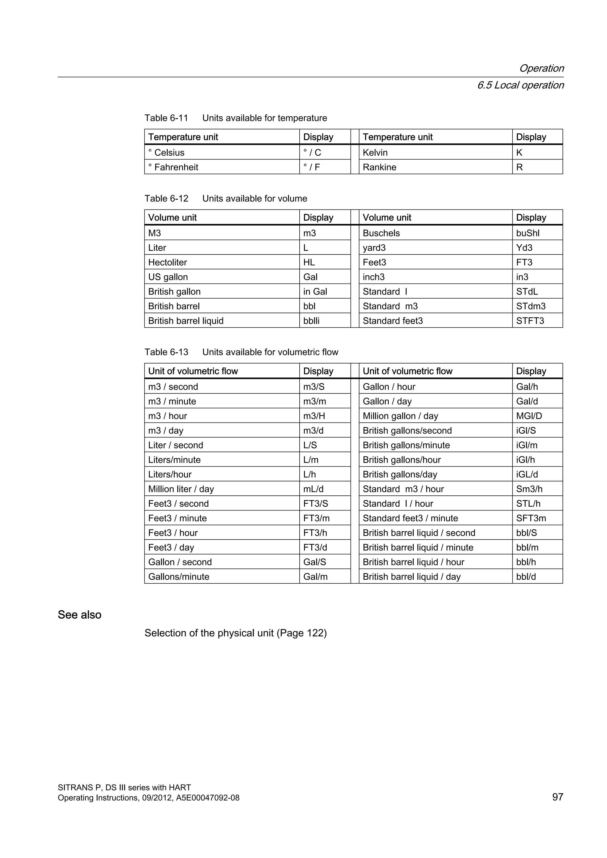
![See also
Measured value display (Page 121)
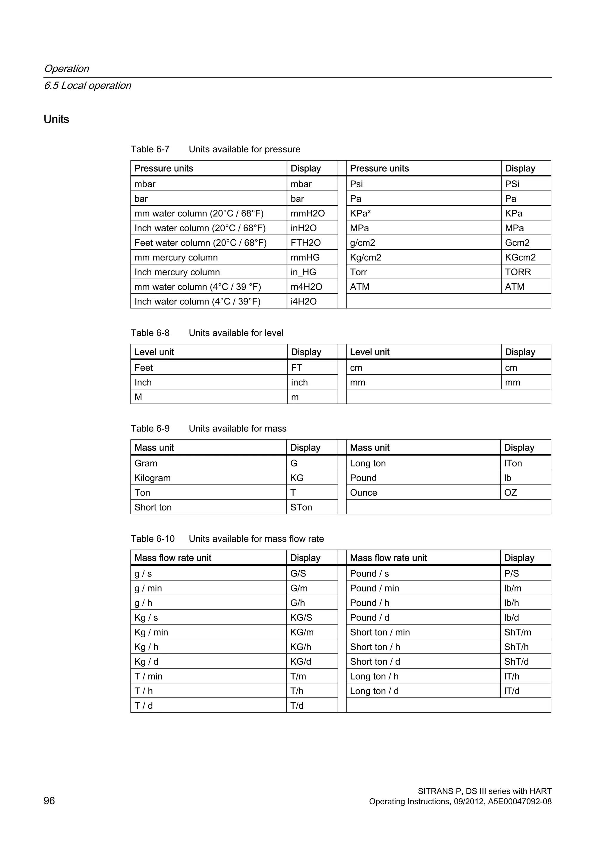
6.5.13 Unit
Introduction
In mode 14, select the physical unit in which the measured value display of the device should
be shown.
Condition
You are familiar with the correct operation of the transmitter and the associated safety notes.
You have already selected the desired measured value display via HART.
Procedure
To adjust the physical unit, proceed as follows:
1. Set mode 14.
2. Select a unit.
Press the [↑] and [↓] buttons simultaneously to set the unit to the first value in the following
table depending on the measuring mode set.
3. Save with the [M] button.
Instructions for selecting the unit
● Unit selection depends on the type of measurement set. For example, only pressure units
are available in "Pressure" measuring mode and only level units are available in the "Level"
measuring mode.
● The displayed measured value is always converted into the new unit. "9.9.9.9.9" appears
on the display when its display capacity is exceeded.
● The selected unit is visible on the display in the measuring mode only if you have selected
the display of a physical unit via HART. "mA" or "%" will be displayed if you have not selected
mode 13, "Measuring mode".
Operation
6.5 Local operation
SITRANS P, DS III series with HART
Operating Instructions, 09/2012, A5E00047092-08 95](https://image.slidesharecdn.com/a5e00047092-07ends3hartexoien-us-150107073133-conversion-gate02/75/Manual-trm-siemens-97-2048.jpg)

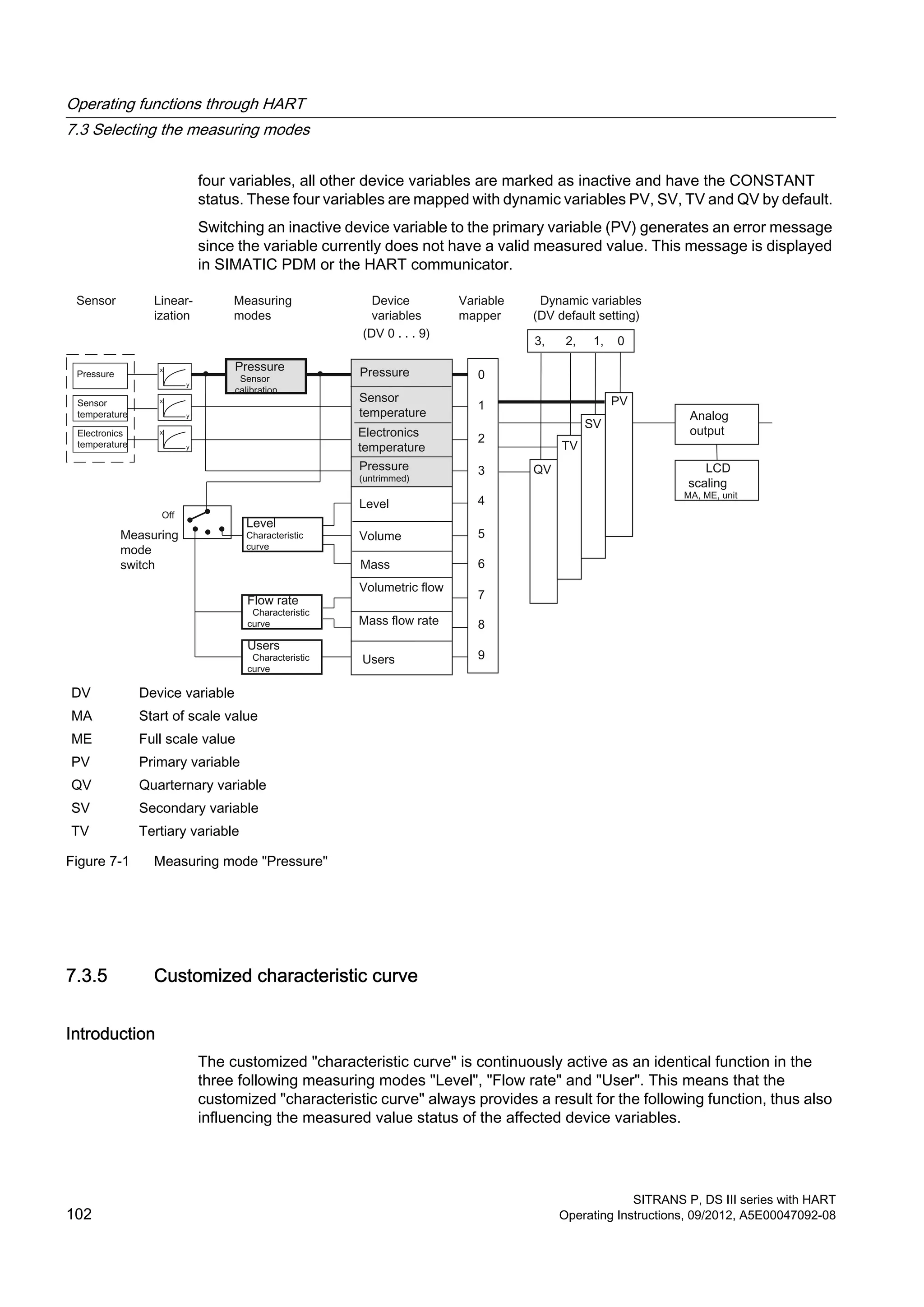
![DV [x] Device variable x
L Level
m Mass
MA Start of scale value
ME Full scale value
P Pressure
V Volume
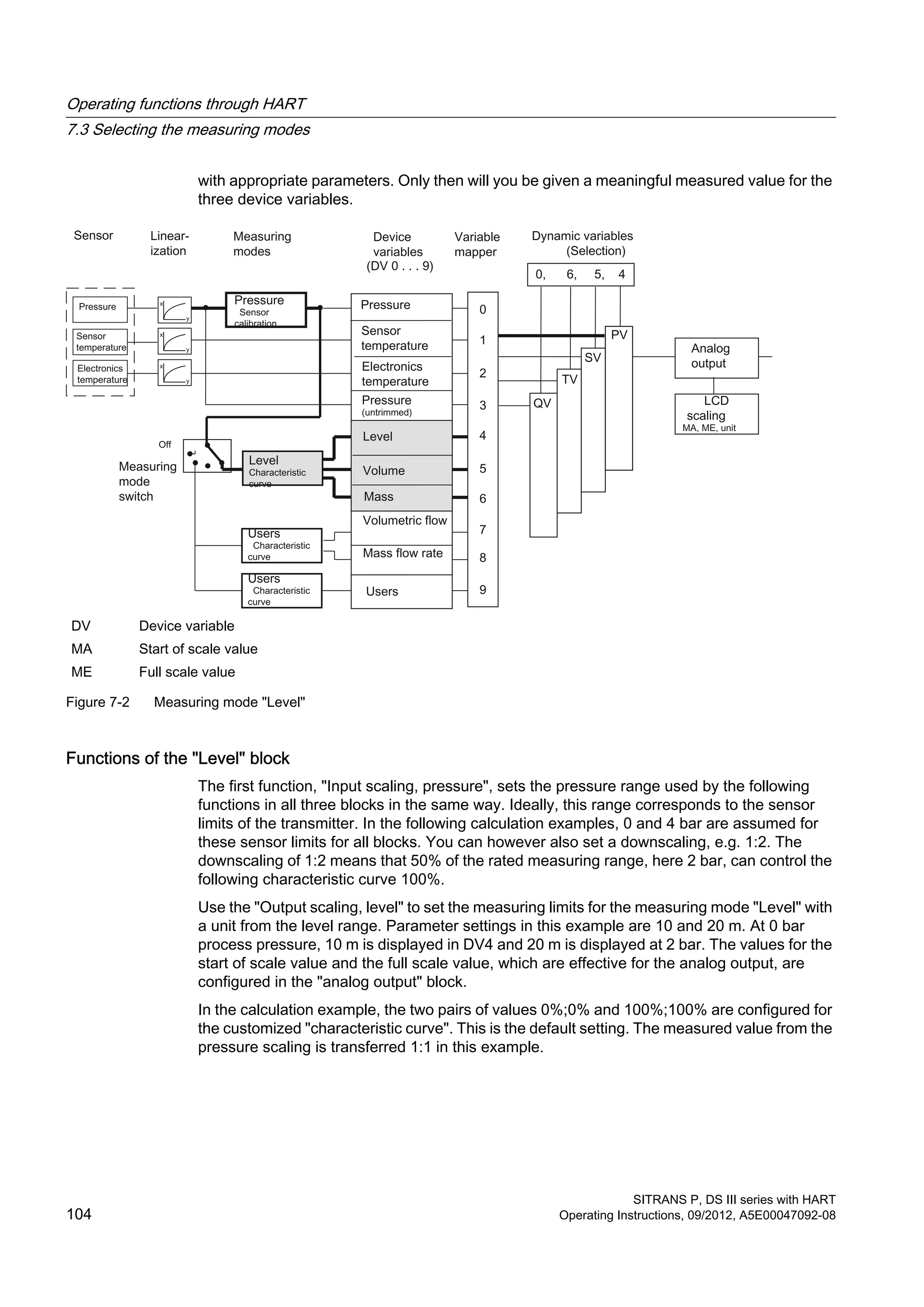
Figure 7-3 Functions of the "Level" block
Configure the "Output scaling, volume" with a unit from the volume range and the measuring
limits for the device variable "Volume". The characteristic curve output directly affects the
volume scaling input.
In the calculation example, for the measuring limits from 0 and 100 l, a volume of 50 l is yielded
for process pressure of 1 bar.
The "Level" parameter setting also still automatically activates the device variable for the mass.
If you have not yet configured a value for the density, the initial value of 1 kg/l is preset. In the
calculation example for the "Mass" device variable, a mass of 250 kg is derived at a density
of 5 kg/l.
Note
When the density changes, the measuring range limits have to be adjusted accordingly.
You can configure all parameter settings for the "Level" block in SIMATIC PDM or the HART
communicator. Activate the "Level" measuring mode for this purpose. For all settings, the
measuring limits may be exceeded by +/-20%. Values which lie above or below that will be
rejected by the device.
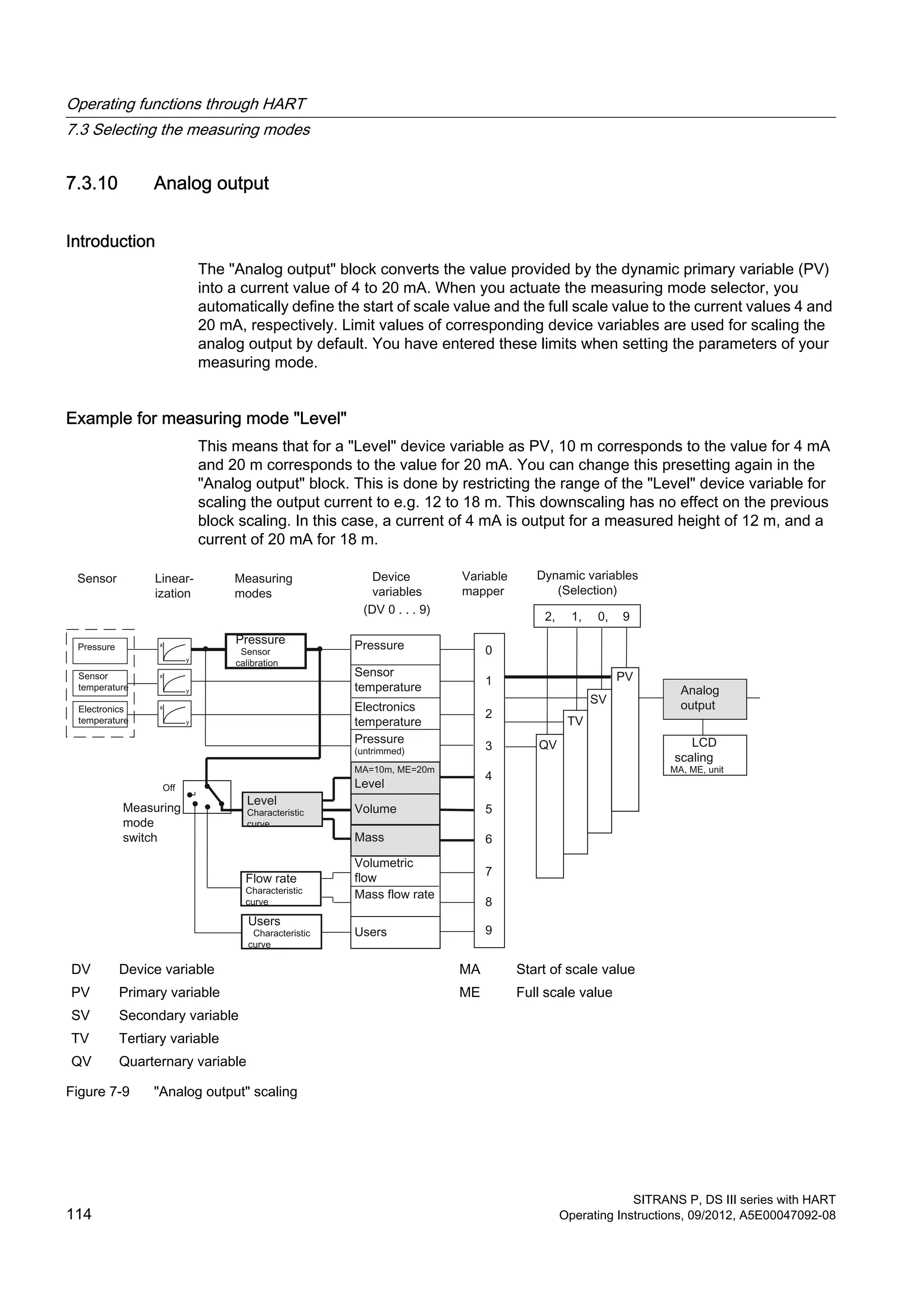
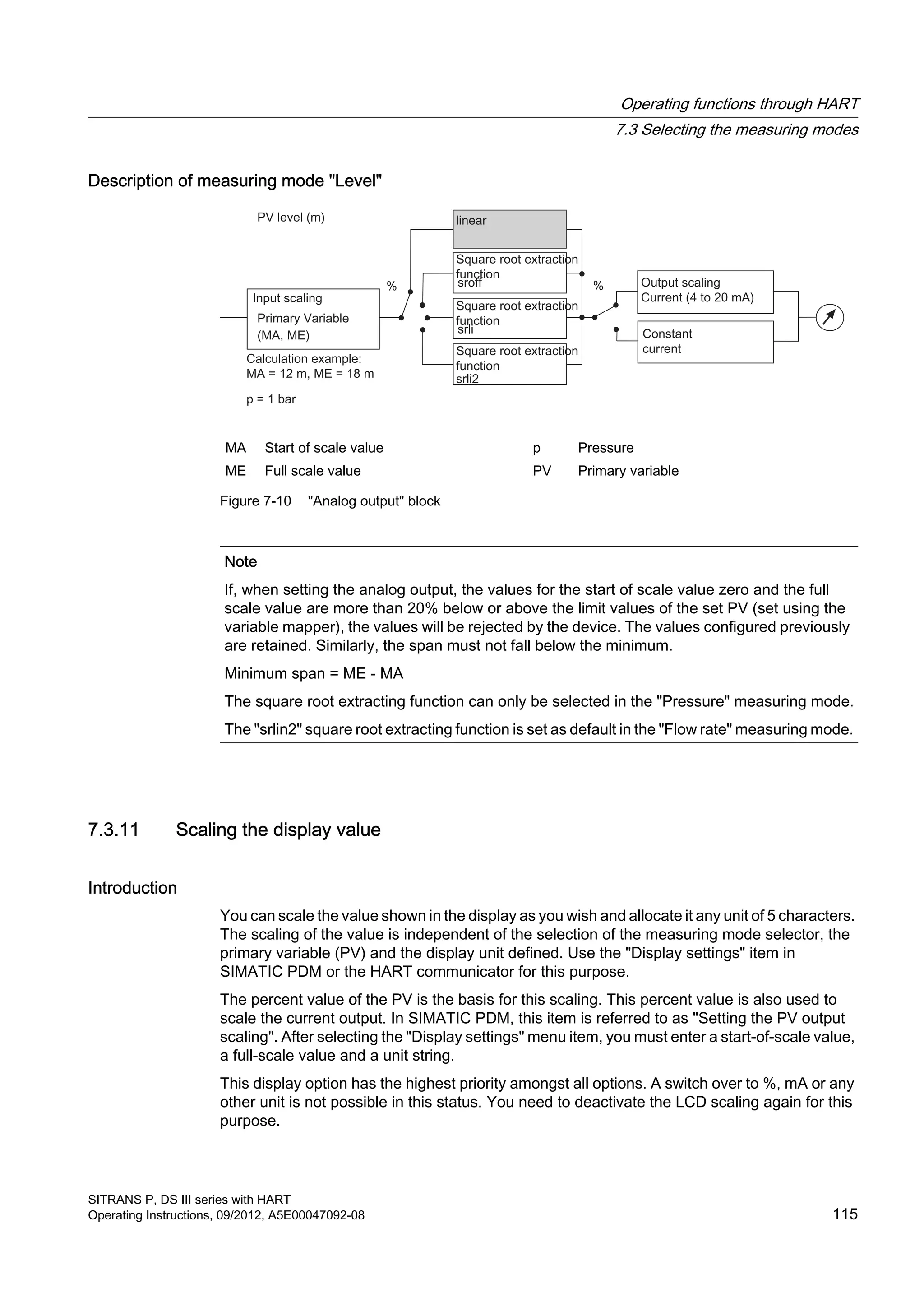
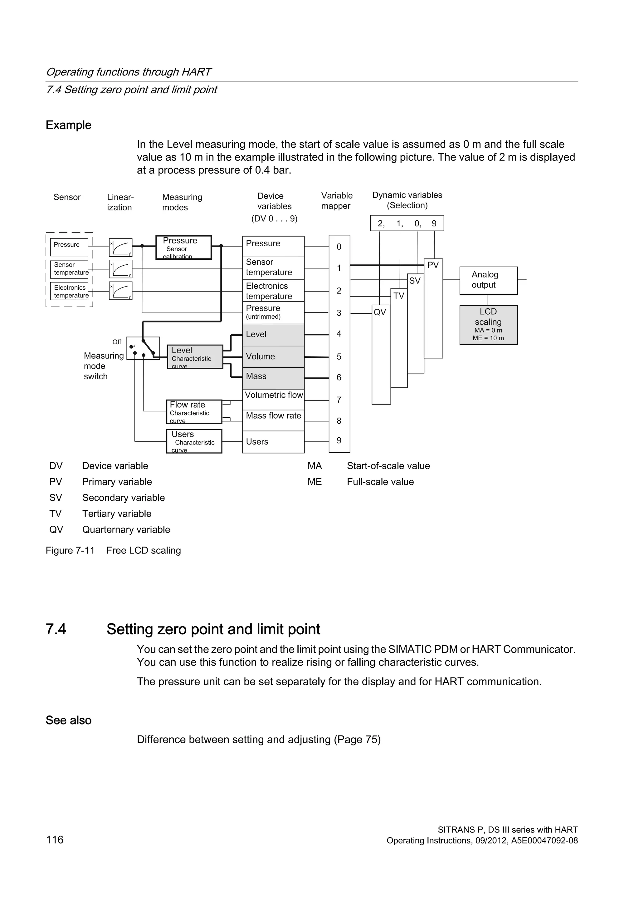
Operating functions through HART
7.3 Selecting the measuring modes
SITRANS P, DS III series with HART
Operating Instructions, 09/2012, A5E00047092-08 105](https://image.slidesharecdn.com/a5e00047092-07ends3hartexoien-us-150107073133-conversion-gate02/75/Manual-trm-siemens-107-2048.jpg)
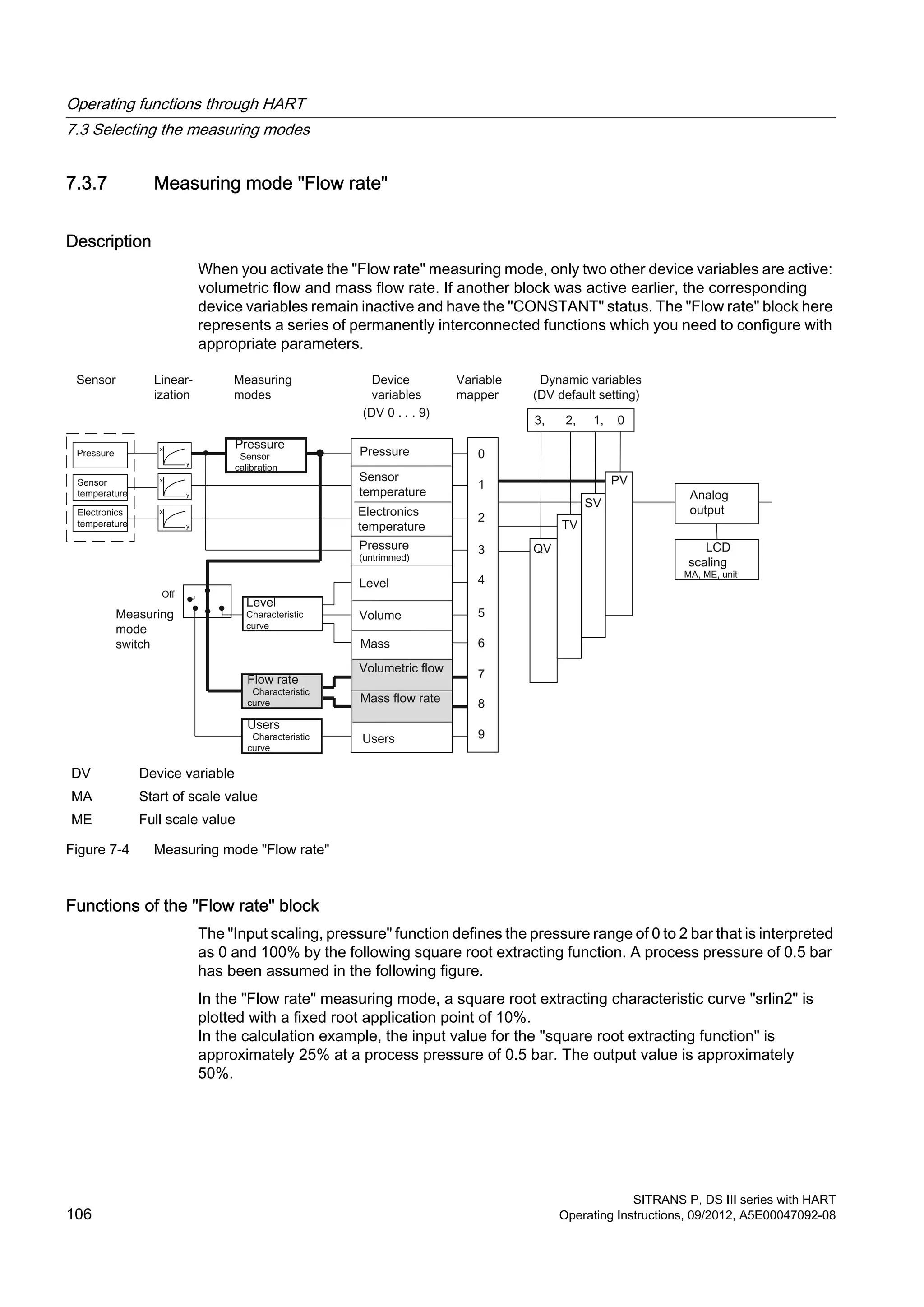
![Note
When using the "Flow rate" block, other square root extracting characteristic curves must be
deactivated if required.
DV [x] Device variable x MF Mass flow rate
MA Start of scale value p Pressure
ME Full scale value VF Volumetric flow
Figure 7-5 Functions of the "Flow rate" block
In the calculation example, the two pairs of values 0%;0% and 100%;50 % are configured for
the customized "characteristic curve". This setting corresponds to a bisection of the input value
for all output values.
Configure the output scaling "volumetric flow" with a unit from the volume flow range and the
measuring limits for the device variable "Volumetric flow". In the calculation example, 0 l/s and
1000 l/s are defined as lower and upper measuring limits. The volumetric flow rate is 250 l/s
at a process pressure of 0.5 bar.
The "Mass flow rate" device variable is automatically activated when the "Flow rate" block is
configured. If you have not yet configured a value for the density, the initial value of 1 kg/l is
preset.
In the calculation example, a mass of 1000 kg/s is derived for the "Mass flow rate" device
variable at a value of 4 kg/l. The density value entered is only used to calculate the mass flow
rate. The entered value of density has no effect on the diaphragm calculation that is to be
carried out by the user.
In SIMATIC PDM or the HART communicator, the "Flow rate" block is configured in an online
dialog box in an extremely compact manner. In this online dialog box, you can compile all
values in a menu and transfer them to the device collectively.
Operating functions through HART
7.3 Selecting the measuring modes
SITRANS P, DS III series with HART
Operating Instructions, 09/2012, A5E00047092-08 107](https://image.slidesharecdn.com/a5e00047092-07ends3hartexoien-us-150107073133-conversion-gate02/75/Manual-trm-siemens-109-2048.jpg)
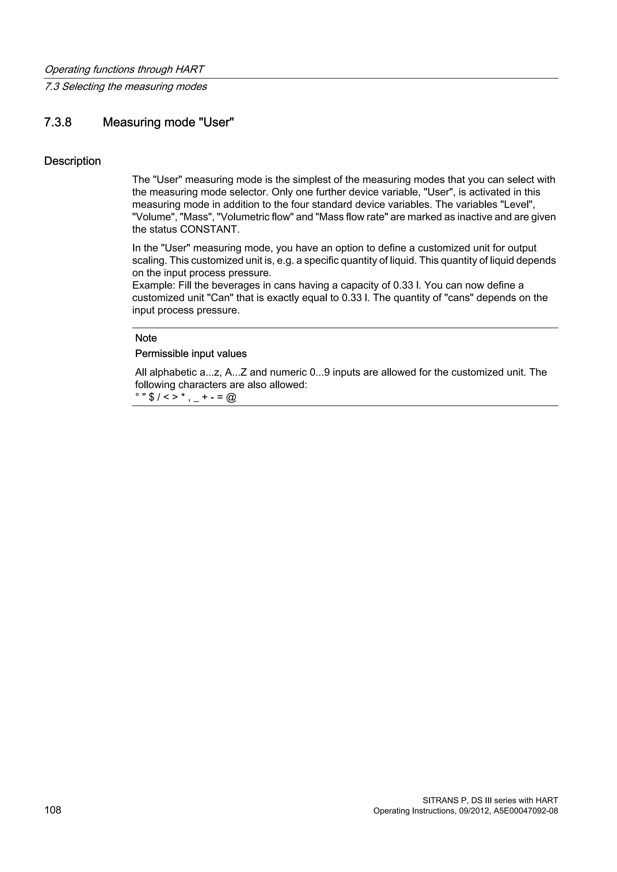
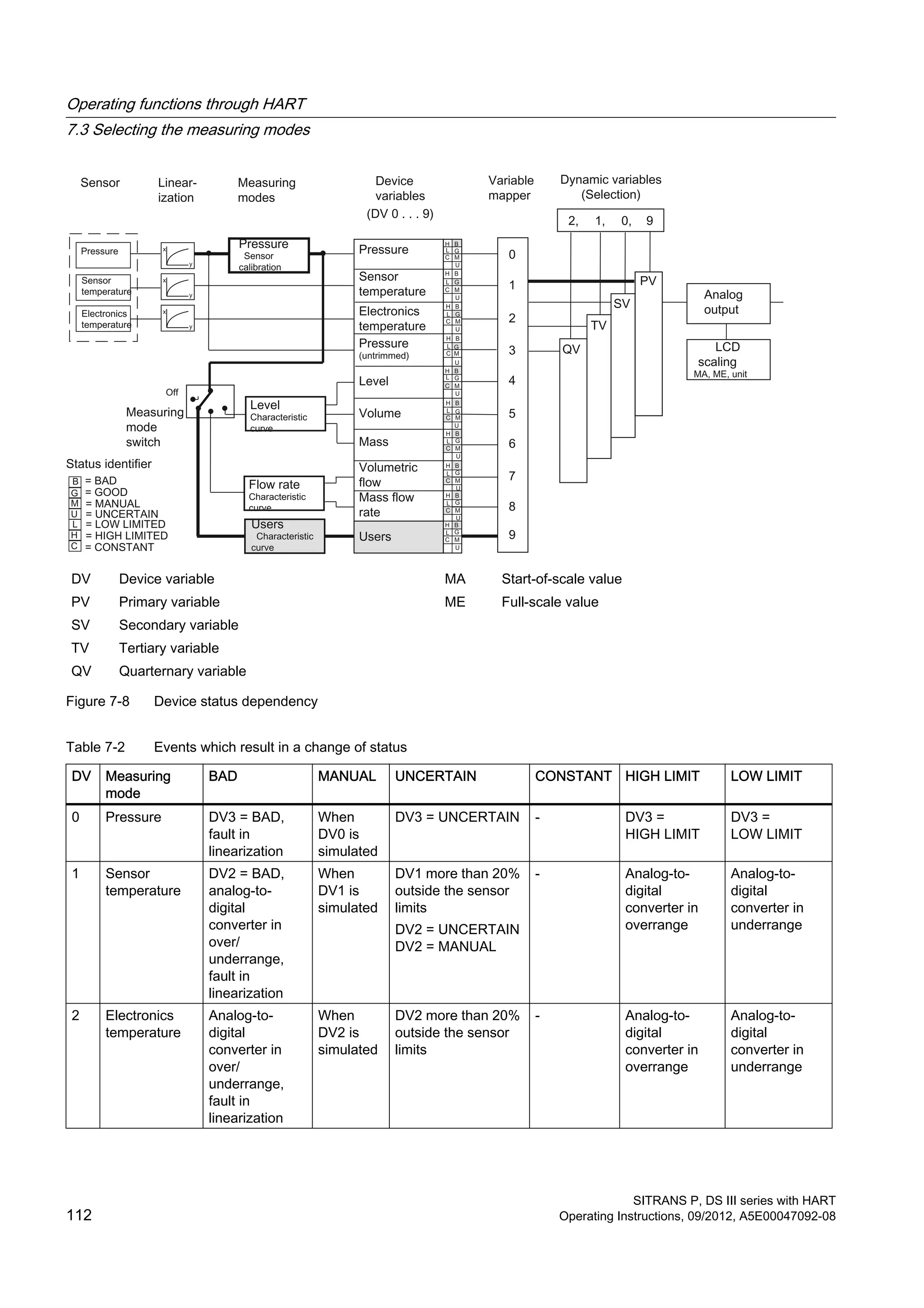
![DV Device variable MA Start of scale value
PV Primary variable ME Full scale value
SV Secondary variable
TV Tertiary variable
QV Quarternary variable
Figure 7-6 Measuring mode "User"
Functions of the "User" block
The first function, "Input scaling, pressure", defines the pressure range which is used by the
customized characteristic curve. Ideally, this range corresponds to the sensor limits.
In the calculation example, 0 and 2 bar are assumed. This means that with process pressure
of 0.5 bar, there is a value of 25% on the characteristic curve.
DV [x] Device variable x MA Start of scale value
p Pressure ME Full scale value
Figure 7-7 Functions of the "User" block
In the calculation example, the two pairs of values 0%;0% and 100%;100% are configured for
the customized "characteristic curve". Any curve shapes can be calculated with the help of 30
Operating functions through HART
7.3 Selecting the measuring modes
SITRANS P, DS III series with HART
Operating Instructions, 09/2012, A5E00047092-08 109](https://image.slidesharecdn.com/a5e00047092-07ends3hartexoien-us-150107073133-conversion-gate02/75/Manual-trm-siemens-111-2048.jpg)
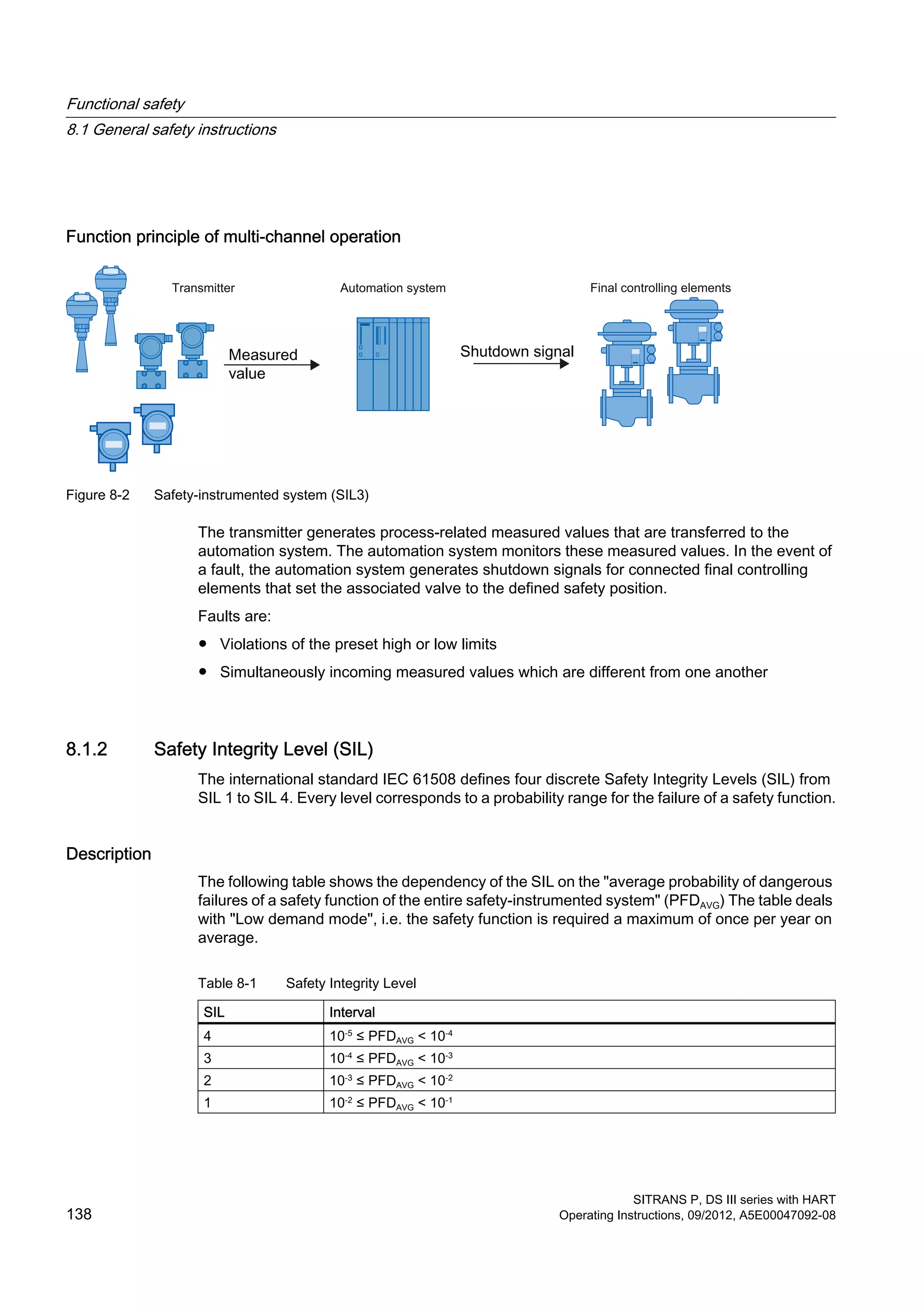
![8.2 Device-specific safety information for single-channel operation (SIL 2)
8.2.1 Safety function
Safety function for pressure transmitters
The safety function of SITRANS P refers to the measurement of pressures. An additional safety
accuracy of 2% of the measuring range (complete span) must be added to the application-
specific measuring error for an output current of 4 to 20 mA.
Total tolerance (safety function) = ± [application-specific measuring error + 2% safety
accuracy].
Pressure transmitter safety accuracy: the maximum effect of an uncritical individual error on
the measured value.
The diagnostics function will respond within 4 seconds in the worst-case scenario.
Note
Use of remote seals
If remote seals are used, the application-specific measurement error is the product of the
transmitter and remote seal measurement errors.
WARNING
Disregarding conditions for fulfilling the safety function
Disregard can result in a malfunction of the process plant or application, e.g. process pressure
too high, maximum level exceeded.
The binding settings and conditions are listed in the chapters "Settings (Page 140)" and
"Safety characteristics (Page 142)".
These conditions must be strictly observed in order to fulfill the safety function.
8.2.2 Settings
The following settings must be adhered to after installing and commissioning as per the
Operating Instructions:
Operation/configuration
While operating/configuring, ensure that the technical data of the pressure transmitter are
adhered to in their respective version.
Functional safety
8.2 Device-specific safety information for single-channel operation (SIL 2)
SITRANS P, DS III series with HART
140 Operating Instructions, 09/2012, A5E00047092-08](https://image.slidesharecdn.com/a5e00047092-07ends3hartexoien-us-150107073133-conversion-gate02/75/Manual-trm-siemens-142-2048.jpg)
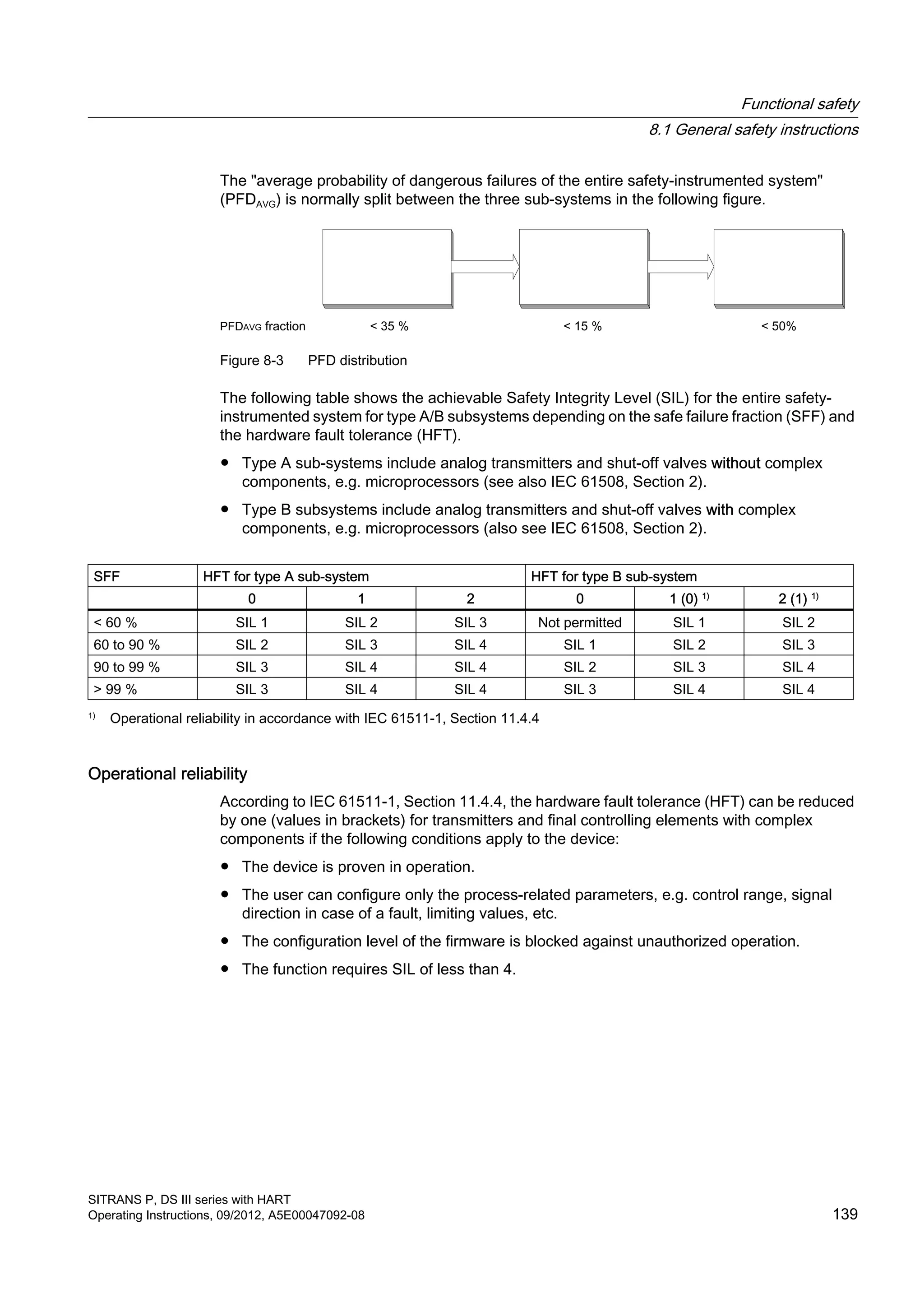
![● The SITRANS P pressure transmitter is only used in applications with a low demand for
the safety function (low demand mode).
● Communication with the HART protocol is used only for the following:
– Device configuration
– Reading diagnostics values
– However, it is not used for operations critical to safety. In particular, the simulation
function must not be activated in safety-related operation.
● The safety-related parameters/settings have been entered by local operation or HART
communication before commencing safety-related operation. They are checked on the local
display.
(see "Settings" section)
● The safety function test has been concluded successfully.
● The transmitter is blocked against unwanted and unauthorized changes/operation.
● The current signal of 4 to 20 mA of the transmitter is evaluated by a safe system.
● Fault rates are calculated on the basis of a Mean Time To Repair (MTTR) of eight hours
(order option C20) or 72 hours (order option C23).
See also
Settings (Page 140)
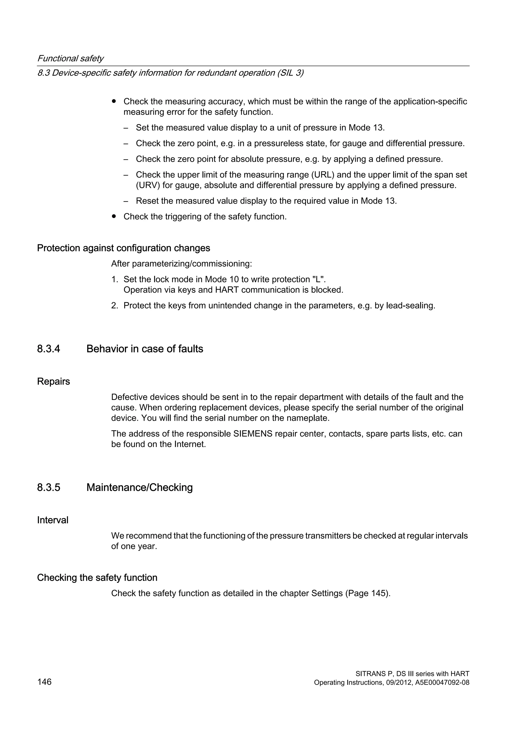
8.3 Device-specific safety information for redundant operation (SIL 3)
8.3.1 Safety function
Safety function for pressure transmitters
The safety function of SITRANS P refers to the measurement of pressures. An additional safety
allowance of 2% of the measuring range (complete span) must be added to the application-
specific measuring error for an output current of 4 to 20 mA.
Total tolerance (safety function) = ± [application-specific measuring error + 2% safety
allowance].
Pressure transmitter safety allowance: the maximum effect of an uncritical individual error on
the measured value.
The diagnostics function will respond within 4 seconds in the worst-case scenario.
Functional safety
8.3 Device-specific safety information for redundant operation (SIL 3)
SITRANS P, DS III series with HART
Operating Instructions, 09/2012, A5E00047092-08 143](https://image.slidesharecdn.com/a5e00047092-07ends3hartexoien-us-150107073133-conversion-gate02/75/Manual-trm-siemens-145-2048.jpg)


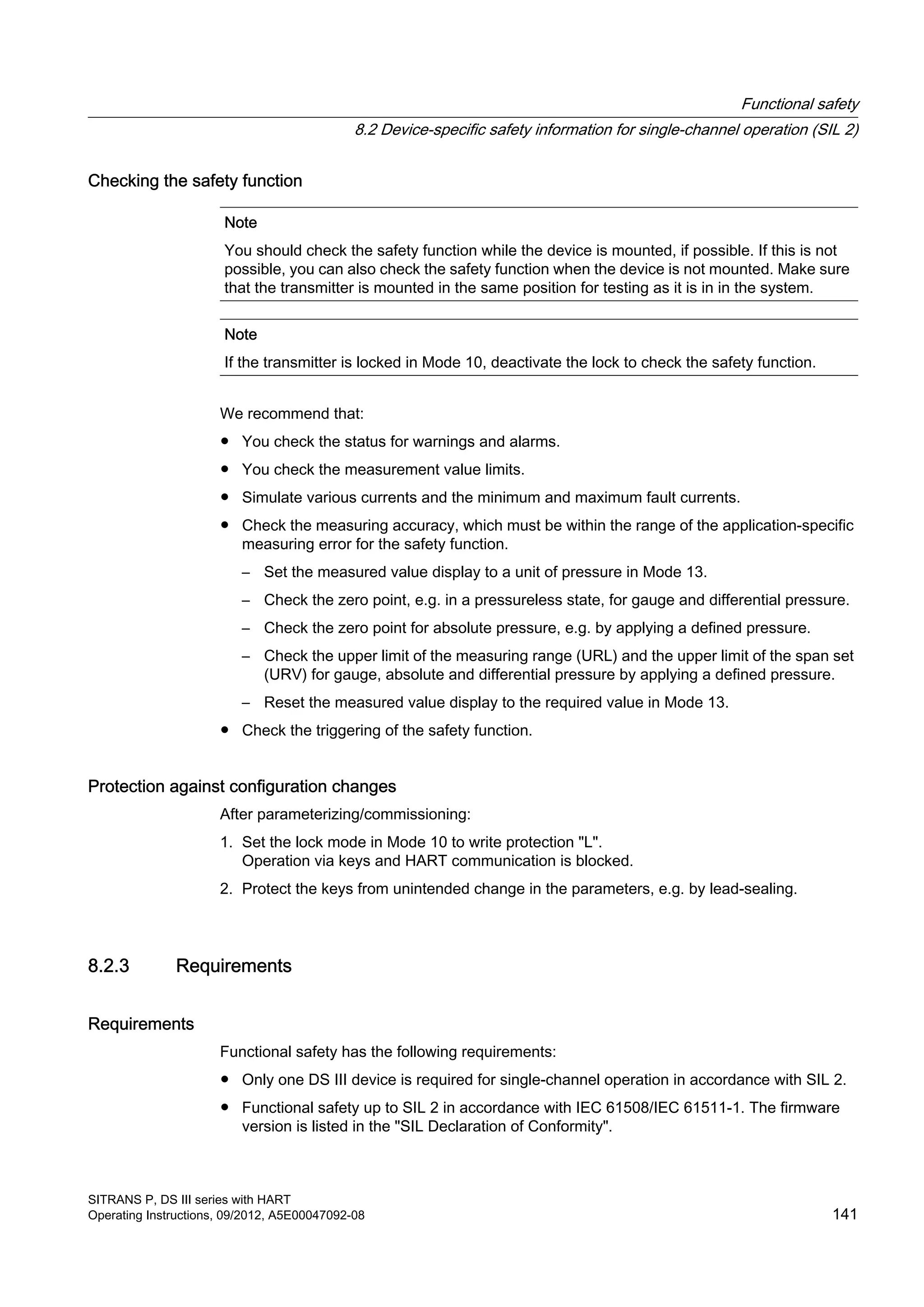
![11.3 Output
Output
HART PROFIBUS PA or Foundation Fieldbus
Output signal 4 … 20 mA Digital PROFIBUS-PA or
Foundation Fieldbus signal
● Lower limit (continuously
adjustable)
3.55 mA, set to 3.84 mA in the factory –
● Upper limit (continuously
adjustable)
23 mA, set to 20.5 mA or optionally
22.0 mA in the factory
–
● Ripple (without HART
communication)
ISS ≤ 0.5 % of the max. output current –
adjustable time constants
damping coefficient
0 … 100 s, continuously adjustable 0 … 100 s, continuously adjustable
Adjustable time constants (T63)
with local operation
0 … 100 s, in steps of 0.1 s
Factory-set to 2 s
0 … 100 s, in steps of 0.1 s
Factory-set to 2 s
● Current transmitter 3.55 … 23 mA –
● Failure signal 3.55 … 23 mA –
Load Resistor R [Ω] –
● Without HART communication –
UH Power supply in V
● With HART communication –
HART communicator (Handheld) R =230 … 1100 Ω –
SIMATIC PDM R =230 … 500 Ω –
Characteristic curve ● Linearly increasing or linearly decreasing
● Linear increase or decrease or square root extracting increasing (only for
DS III differential pressure and flow rate)
Bus physics – IEC 61158-2
Polarity-independent – Yes
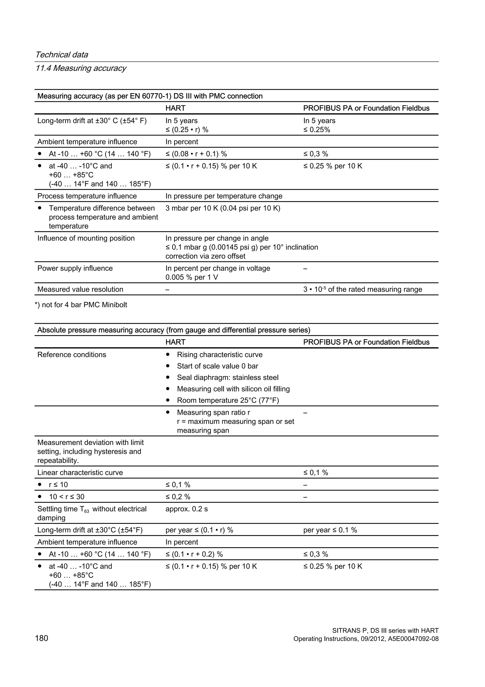
11.4 Measuring accuracy
Measuring accuracy (as per EN 60770-1) gauge pressure
HART PROFIBUS PA or Foundation Fieldbus
Reference conditions ● Rising characteristic curve
● Start of scale value 0 bar
● Seal diaphragm: stainless steel
● Measuring cell with silicon oil filling
● Room temperature 25°C (77°F)
● Measuring span ratio r
r = maximum measuring span or set
measuring span
–
Technical data
11.4 Measuring accuracy
SITRANS P, DS III series with HART
Operating Instructions, 09/2012, A5E00047092-08 177](https://image.slidesharecdn.com/a5e00047092-07ends3hartexoien-us-150107073133-conversion-gate02/75/Manual-trm-siemens-179-2048.jpg)

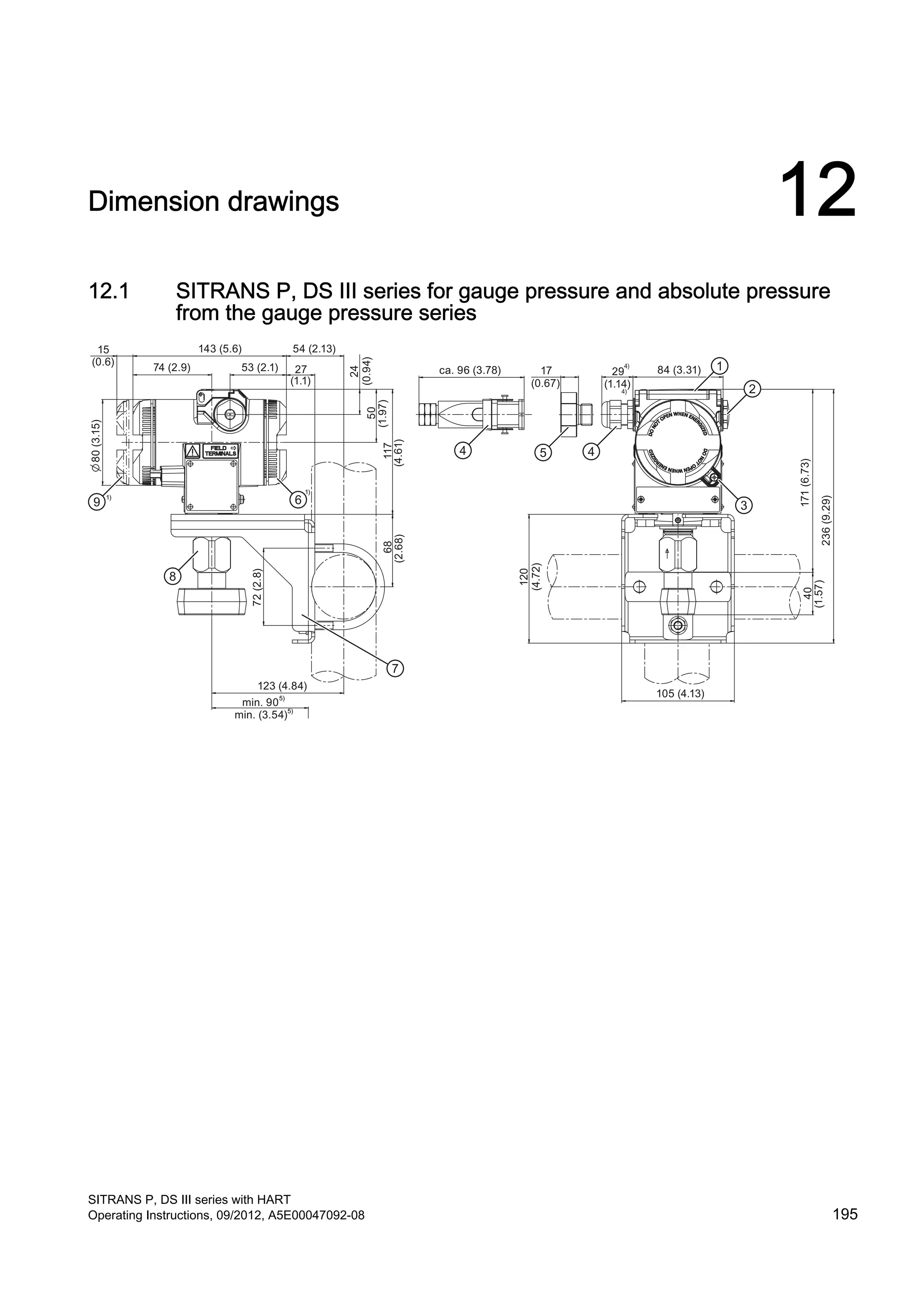
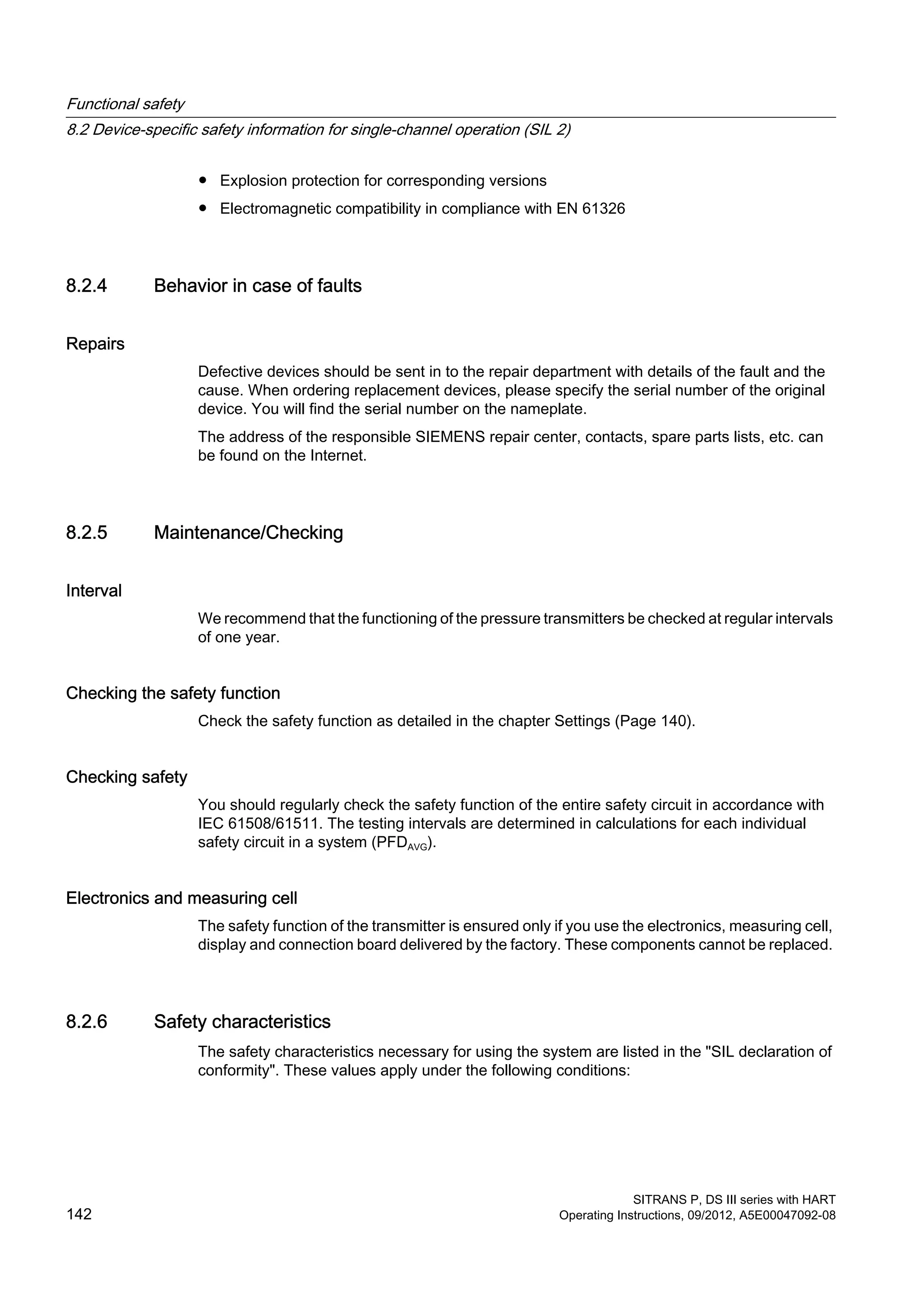
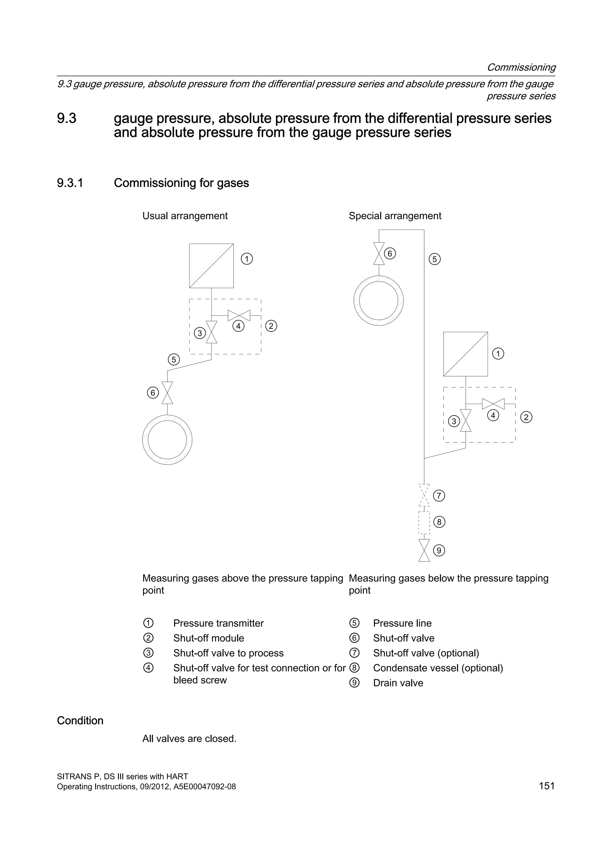
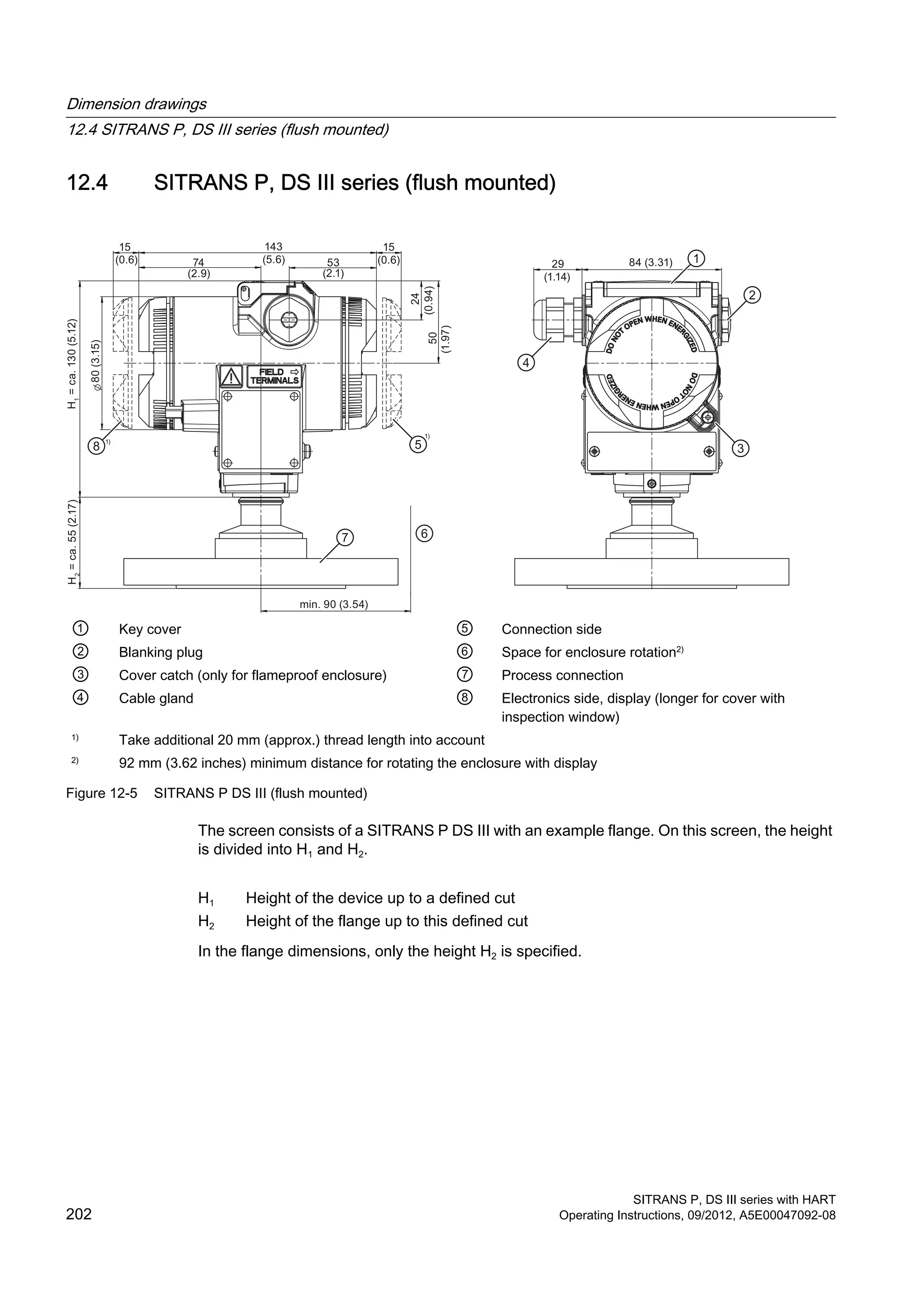
![① Key cover
② Blanking plug
③ Cover catch (only for "flameproof enclosure" type of protection)
④ Electrical connection:
● Threaded joint Pg 13.5 (adapter)2)3)
,
● Threaded joint M20 x 1.53),
● Threaded joint 1
/2-14 NPT
● Han 7D/Han 8D plug2) 3)
● M12 connector
⑤ Han 7D/Han 8D adapter
⑥ Connection side
⑦ Mounting bracket (optional)
⑧ Process connection:
● 1
/2-14 NPT,
● Connection pin G1
/2A or
● Oval flange
⑨ Electronics side, display (longer for cover with inspection window)
1)
Take additional 20 mm (0.79 inches) thread length into account
2)
Not with "flameproof enclosure" type of protection
3)
Not for "FM + CSA [is + XP]" type of protection
4)
For Pg 13.5 with adapter approx 45 mm (1.77 inches)
5)
Minimum distance for rotating
Figure 12-1 Pressure transmitter SITRANS P, DS III series for absolute pressure, from gauge pressure series, dimensions
in mm (inches)
Dimension drawings
12.1 SITRANS P, DS III series for gauge pressure and absolute pressure from the gauge pressure series
SITRANS P, DS III series with HART
196 Operating Instructions, 09/2012, A5E00047092-08](https://image.slidesharecdn.com/a5e00047092-07ends3hartexoien-us-150107073133-conversion-gate02/75/Manual-trm-siemens-198-2048.jpg)
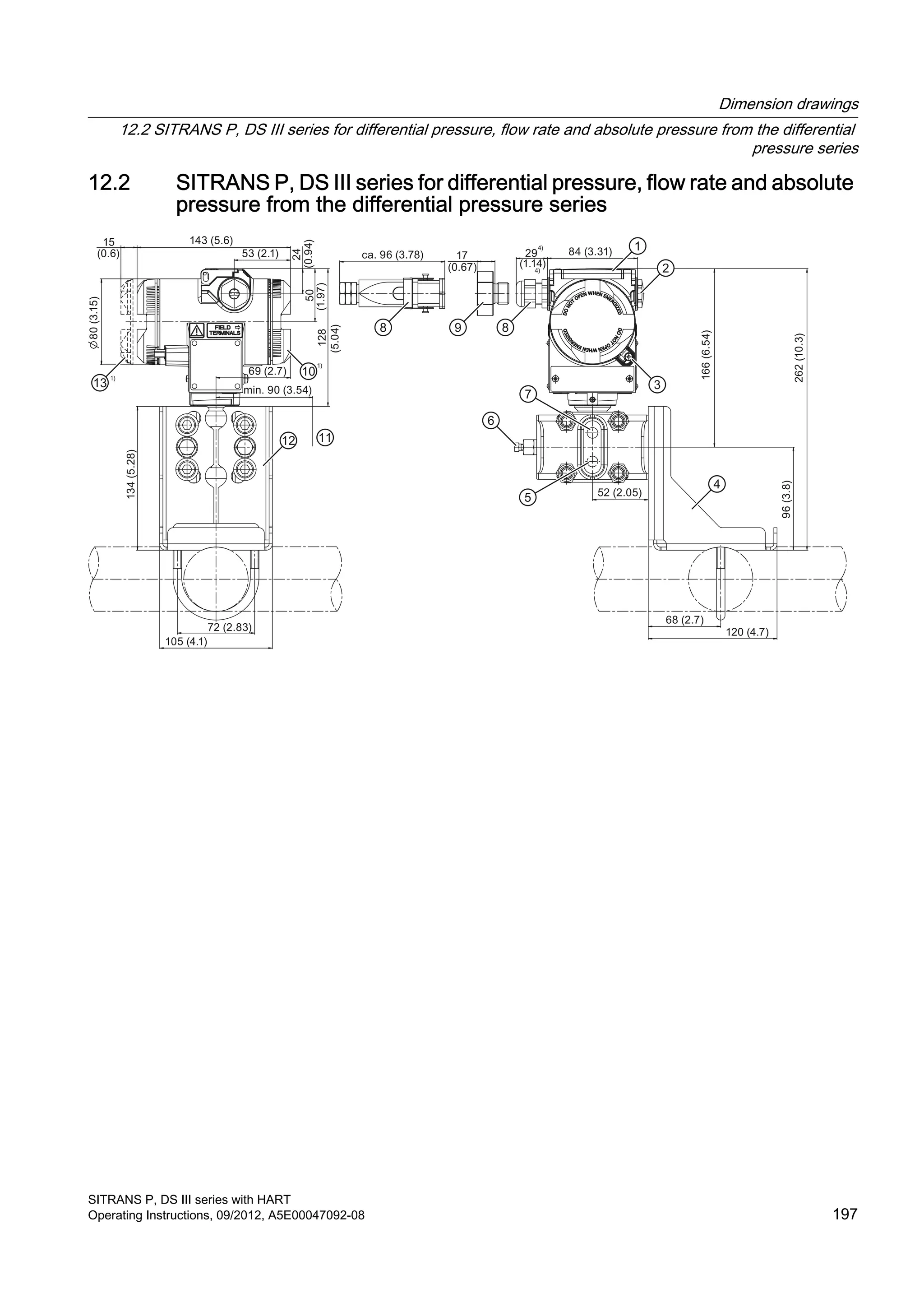
![① Key cover
② Blanking plug
③ Cover catch (only for "flameproof enclosure" type of protection)
④ Mounting bracket (optional)
⑤ Lateral ventilation for gas measurement (addition H02)
⑥ Sealing plug, with valve (optional)
⑦ Lateral ventilation for liquid measurement
⑧ Electrical connection:
● Pg 13.5 gland (adapter)2)3)
● M20 x 1.5 gland3)
● 1
/2-14 NPT gland
● Han 7D/Han 8D plug2) 3)
● M12 connector
⑨ Han 7D/Han 8D adapter
⑩ Connection side
⑪ Space for enclosure rotation5)
⑫ Process connection: 1
/4-18 NPT (EN 61518)
⑬ Electronics side, display (longer for cover with inspection window)
1)
Take an additional 20 mm (0.79 inches) thread length into account
2)
Not with "flameproof enclosure" type of protection
3)
Not for "FM + CSA [is + XP]" type of protection
4)
For Pg 13.5 with adapter, approx 45 mm (1.77 inches)
5)
92 mm (3.62 inches) minimum distance for rotating the enclosure with display
Figure 12-2 Pressure transmitter SITRANS P, DS III series for differential pressure and flow rate, dimensions in mm (inches)
Dimension drawings
12.2 SITRANS P, DS III series for differential pressure, flow rate and absolute pressure from the differential
pressure series
SITRANS P, DS III series with HART
198 Operating Instructions, 09/2012, A5E00047092-08](https://image.slidesharecdn.com/a5e00047092-07ends3hartexoien-us-150107073133-conversion-gate02/75/Manual-trm-siemens-200-2048.jpg)
![80(3.15)
15
(0.6)
143 (5.6)
53 (2.1) ca. 96 (3.78) 17
(0.67)
29
(1.14)
84 (3.31)
128(5.04)
ca.217(8.54)
ca. 87 (3.43)
ca.85(3.35)
min 90 (3.54)
60 (2.36)
65 (2.56)
24
(0.94)50
(1.97)
① Key cover
② Blanking plug
③ Cover catch (only for "flameproof enclosure" type of protection)
④ Sealing plug, with valve (optional)
⑤ Process connection: 1
/4-18 NPT (EN 61518)
⑥ Electrical connection:
● Pg 13.5 gland (adapter)2)3)
● M20 x 1.5 gland3)
● 1
/2-14 NPT gland
● Han 7D/Han 8D plug2) 3)
● M12 connector
⑦ Han 7D/Han 8D adapter
⑧ Connection side
⑨ Space for enclosure rotation8)
⑩ Electronics side, display (longer for cover with inspection window)
1)
Take an additional 20 mm (0.79 inches) thread length into account
2)
Not with "flameproof enclosure" type of protection
3)
Not for "FM + CSA [is + XP]" type of protection
4)
For Pg 13.5 with adapter, approx 45 mm (1.77 inches)
5)
74 mm (2.9 inch) for PN ≥ 420 (MAWP ≥ 6092 psi)
6)
219 mm (8.62 inches) for PN ≥ 420 (MAWP ≥ 6092 psi)
7)
91 mm (3.6 inches) for PN ≥ 420 (MAWP ≥ 6092 psi)
8)
92 mm (3.62 inches) minimum distance for rotating the enclosure with display
Figure 12-3 Pressure transmitter SITRANS P, DS III series for differential pressure and flow rate with caps for vertical
differential pressure lines, dimensions in mm (inches)
Dimension drawings
12.2 SITRANS P, DS III series for differential pressure, flow rate and absolute pressure from the differential
pressure series
SITRANS P, DS III series with HART
Operating Instructions, 09/2012, A5E00047092-08 199](https://image.slidesharecdn.com/a5e00047092-07ends3hartexoien-us-150107073133-conversion-gate02/75/Manual-trm-siemens-201-2048.jpg)
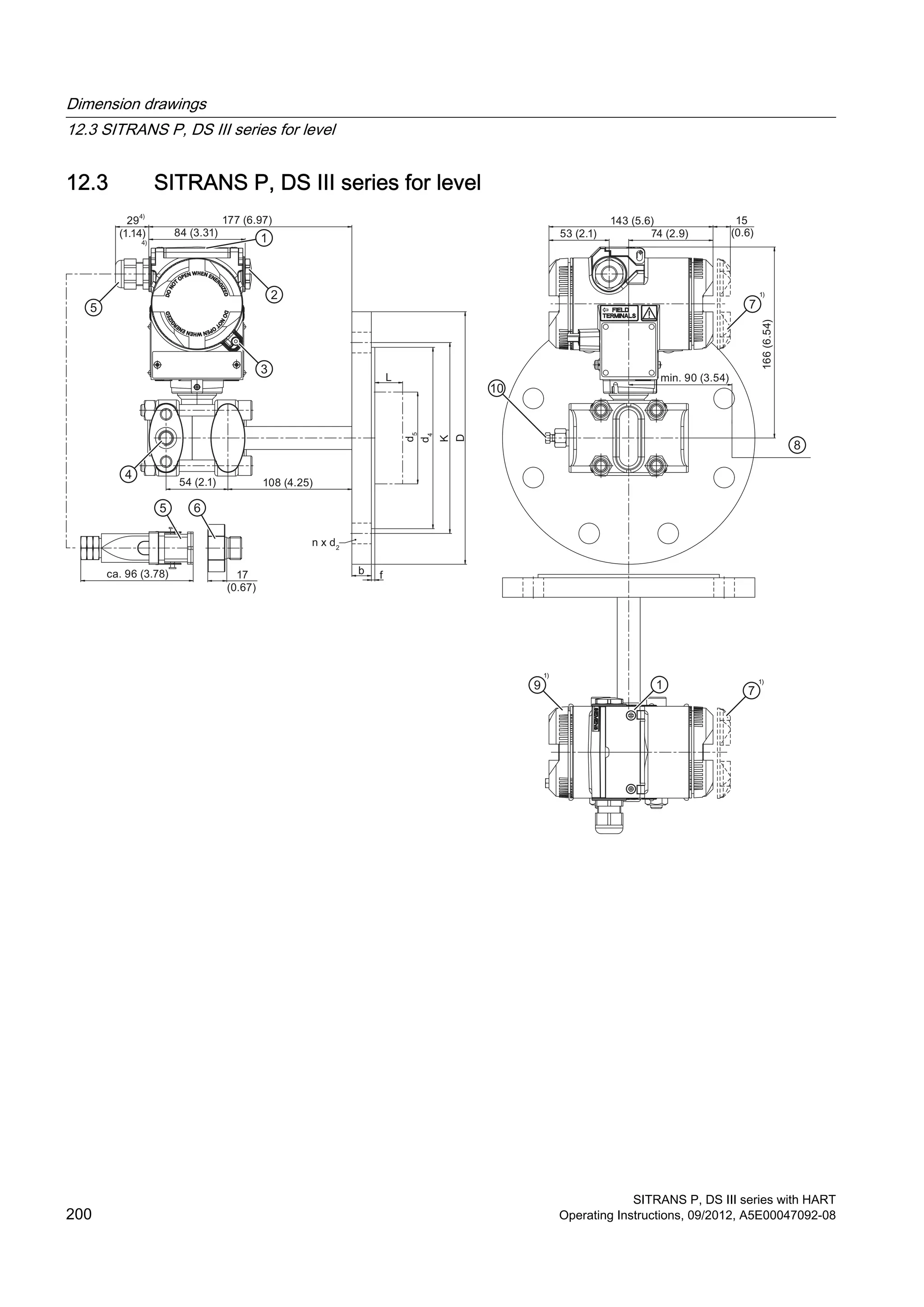
![① Key cover
② Blanking plug
③ Cover catch (only for "flameproof enclosure" type of protection)
④ Process connection: Minus side 1
/4-18 NPT (EN 61518)
⑤ Electrical connection:
● Pg 13.5 gland (adapter)2)3)
● M20 x 1.5 gland3)
● 1
/2-14 NPT gland
● Han 7D/Han 8D plug2) 3)
● M12 connector
⑥ Han 7D/Han 8D adapter
⑦ Electronics side, display (longer for cover with inspection window)
⑧ Space for enclosure rotation5)
⑨ Connection side
⑩ Sealing plug with valve (optional)
1)
Take an additional 20 mm (0.79 inches) thread length into account
2)
Not with "flameproof enclosure" type of protection
3)
Not for "FM + CSA [is + XP]" type of protection
4)
For Pg 13.5 with adapter, approx 45 mm (1.77 inches)
5)
92 mm (3.62 inches) minimum distance for rotating the enclosure with display
Figure 12-4 Pressure transmitter SITRANS P, DS III series for level, including mounting flange, dimensions in mm (inches)
Dimension drawings
12.3 SITRANS P, DS III series for level
SITRANS P, DS III series with HART
Operating Instructions, 09/2012, A5E00047092-08 201](https://image.slidesharecdn.com/a5e00047092-07ends3hartexoien-us-150107073133-conversion-gate02/75/Manual-trm-siemens-203-2048.jpg)


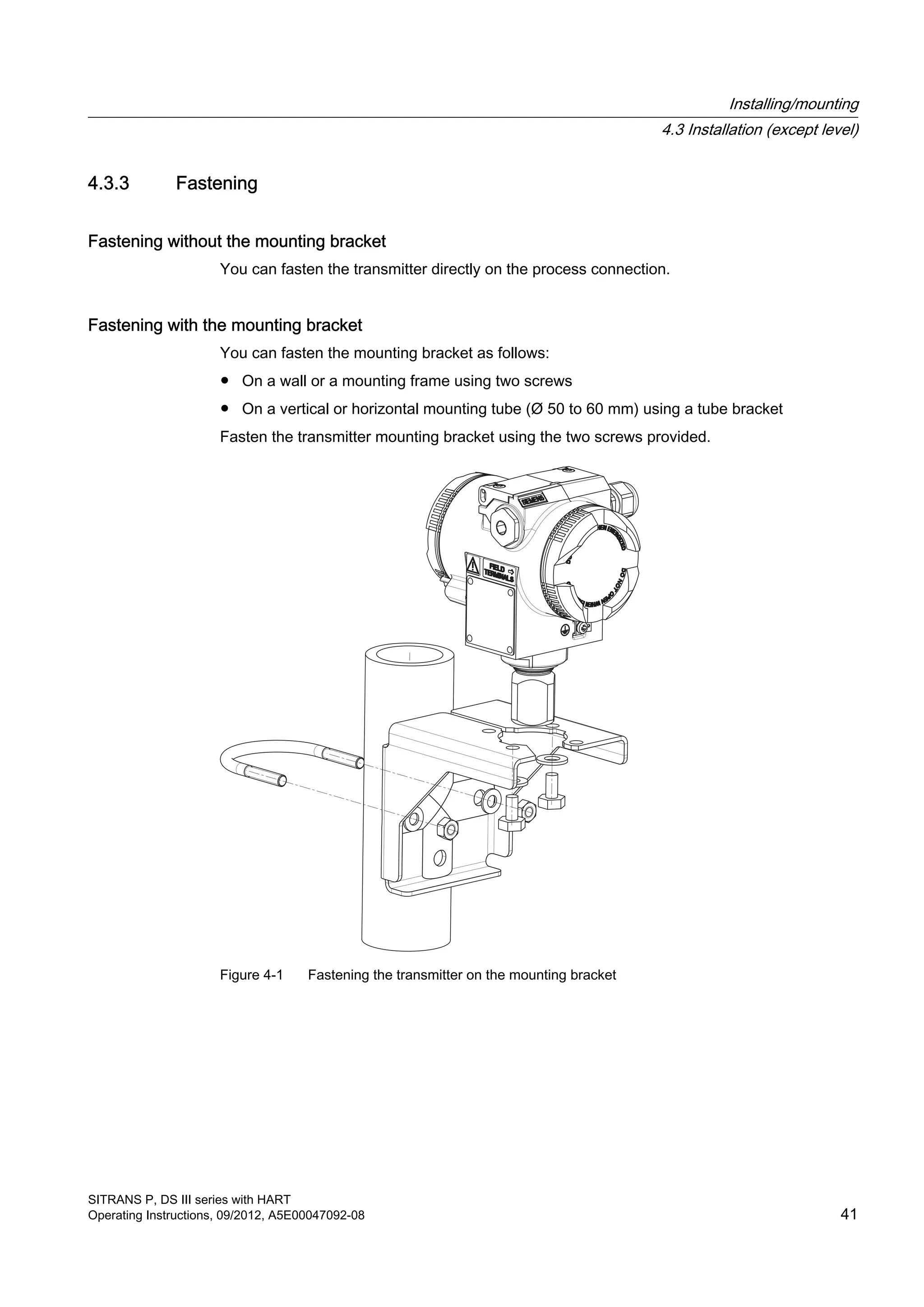
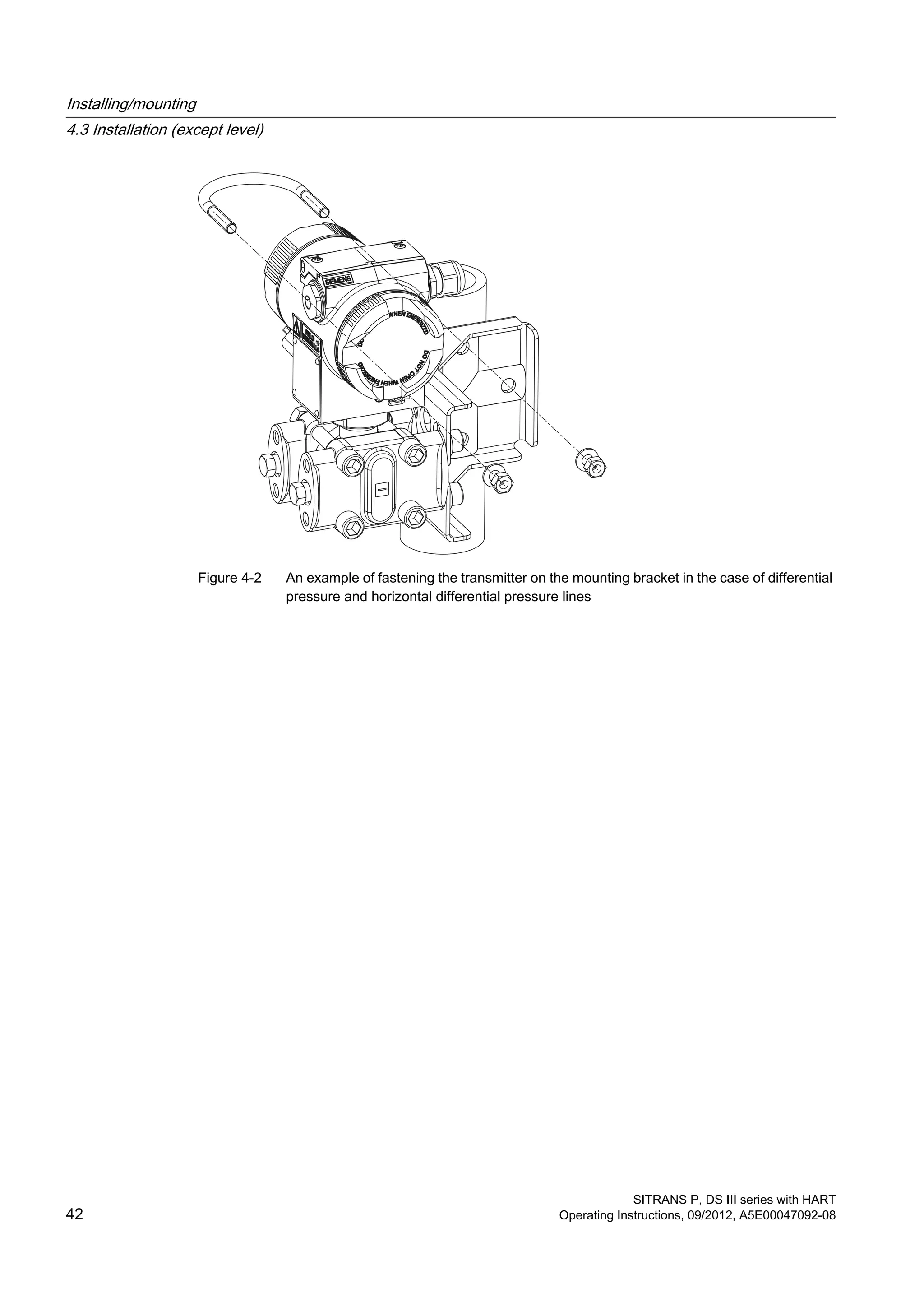
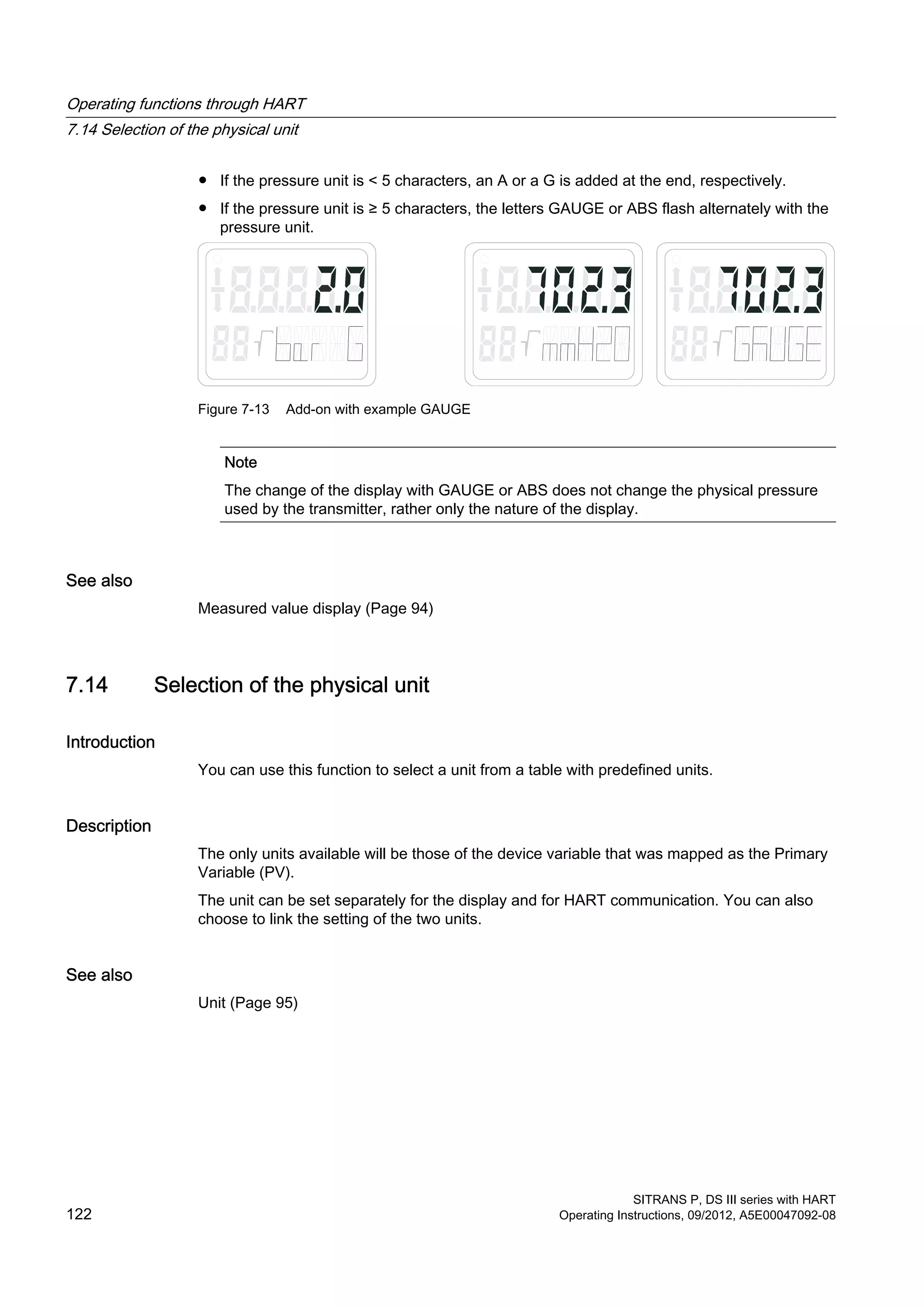
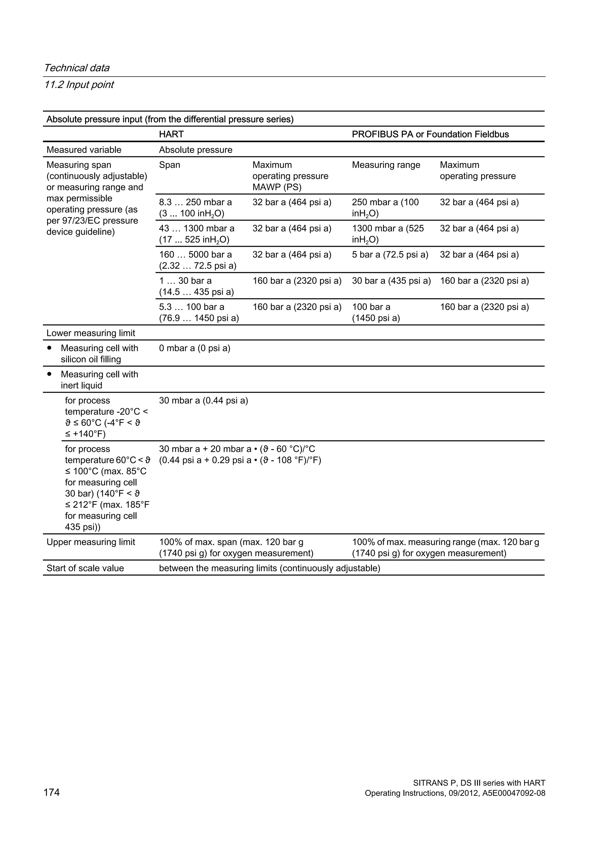
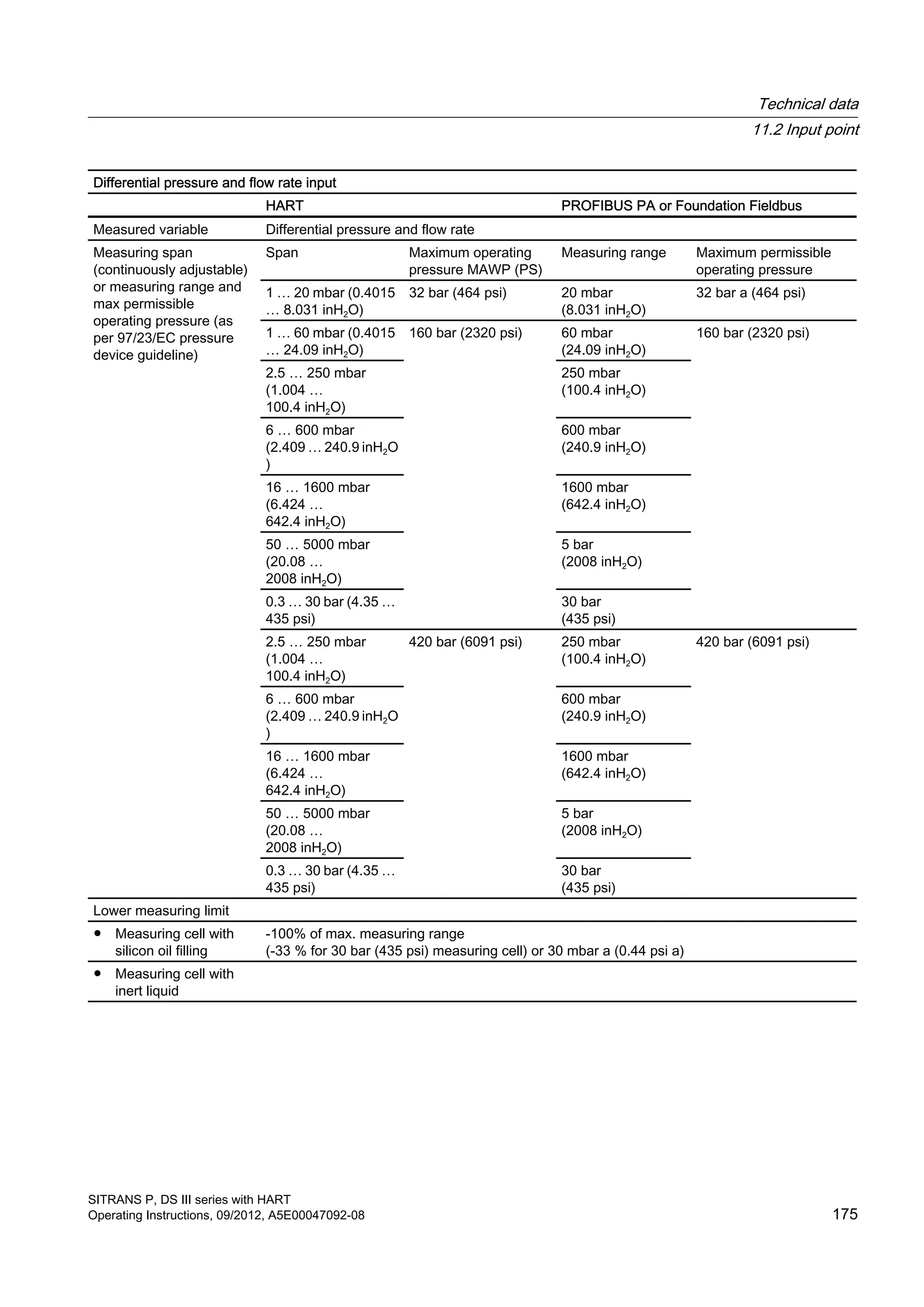
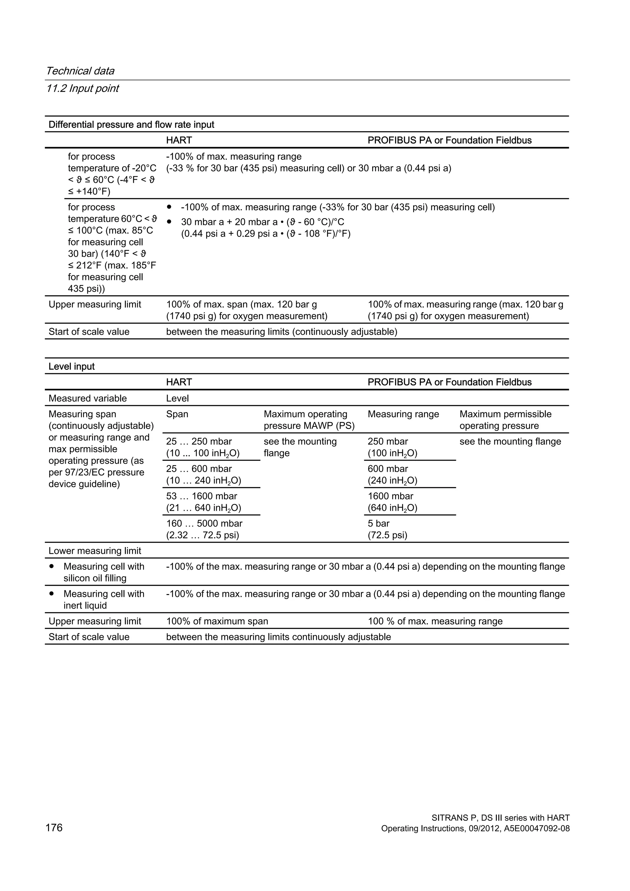
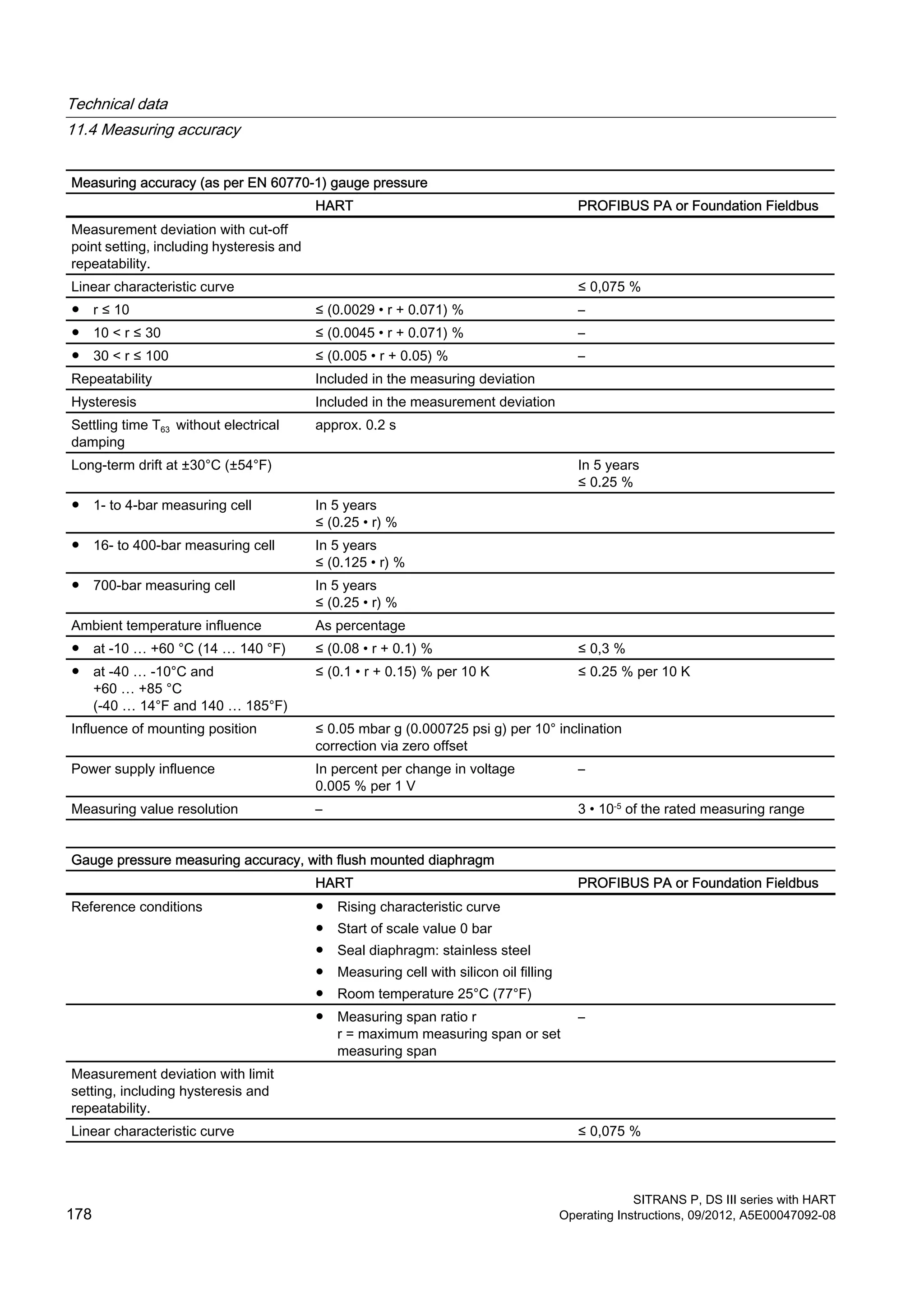
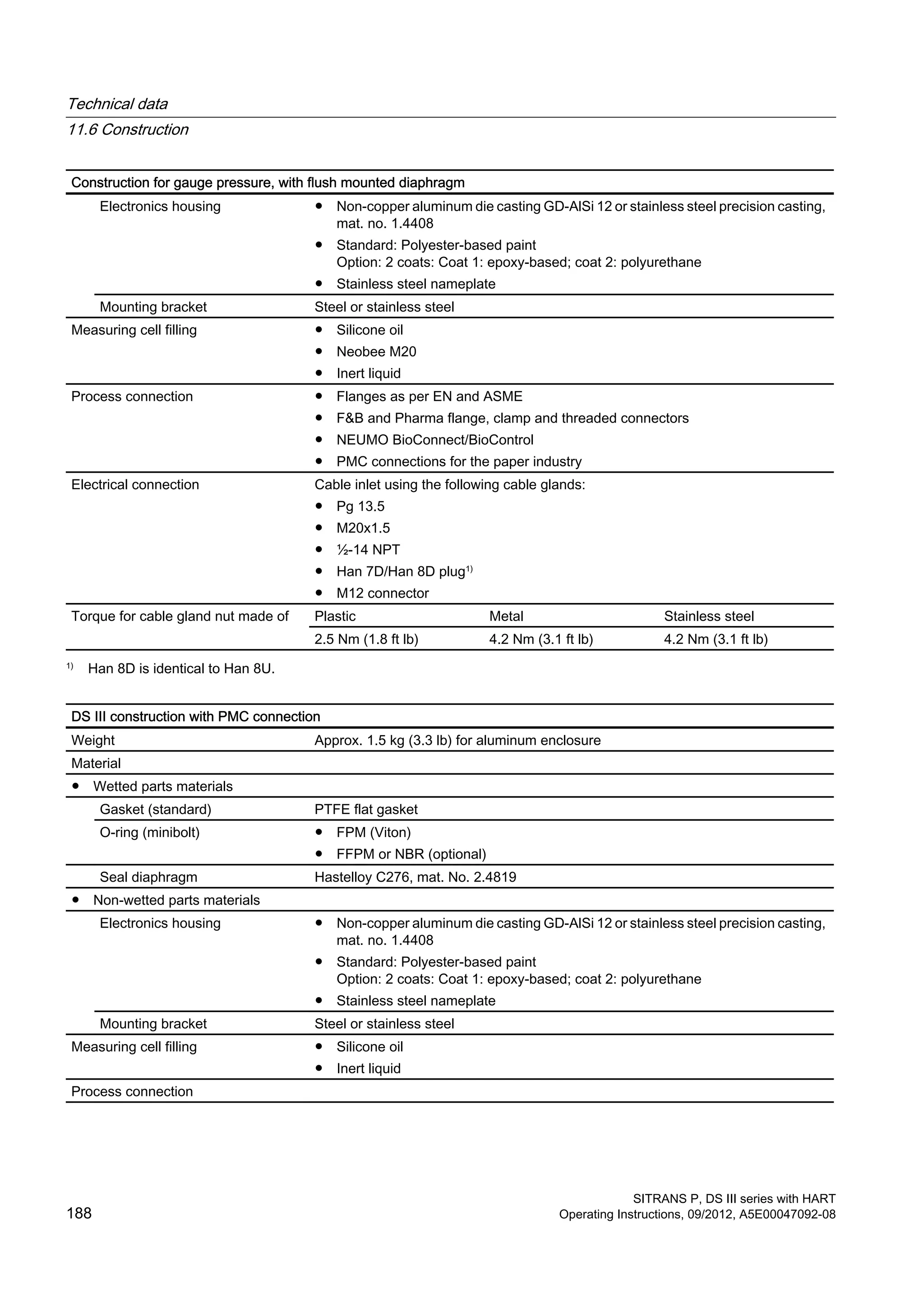
SITRANS P, DS III series with HART is a pressure transmitter that provides precise measurement of pressure, level, differential pressure and flow. It has a digital display and HART communication capability. The document covers safety instructions, descriptions of components and operation, installation, commissioning, maintenance and technical specifications. It is intended to ensure proper use of the transmitter in various process applications.


![Coded Agents – with UiPath SDK + LangGraph [Virtual Hands-on Workshop]](https://cdn.slidesharecdn.com/ss_thumbnails/codedagentsdeck-251215155422-5497c599-thumbnail.jpg?width=640&height=640&fit=bounds)


![Vibe Coding vs. Spec-Driven Development [Free Meetup]](https://cdn.slidesharecdn.com/ss_thumbnails/vibecodingvsspecdrivendevelopment-251209105622-43f455e7-thumbnail.jpg?width=640&height=640&fit=bounds)


