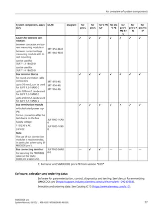
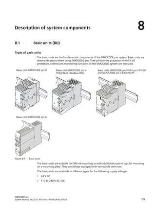
SIMOCODE pro is a motor management and control system for industrial applications. It consists of modular components including basic units, measuring modules, and expansion modules. The system provides protection, monitoring, control and communication functions. It can be integrated into various fieldbus systems and used in a wide range of industrial applications and areas. The manual provides detailed information on the system components, their mounting and wiring, commissioning processes, and safety guidelines for use in hazardous environments.


![you and the relevant licensor. To clarify matters, your attention is drawn to the fact that SIEMENS
shall not cede any warranty obligations on behalf of or as an obligation for a third-party licensor.
NOTICE
Open source software and/or third-party software included in this product
Please note the following license terms and conditions and copyright notices applicable to the
open source software and/or other components (or parts thereof):
Component Open Source
Software
[Yes/No]
Acknowledgements/
Comments
License conditions and copyright notices
tiva ware - 2.1.0 NO LICENSE AND COPYRIGHT INFORMATION FOR COMPO‐
NENT TIVA PRODUCTS - 2.1.0 (see below)
LICENSE CONDITIONS AND COPYRIGHT NOTICES
Commercial Software: tiva ware - 2.1.0
Enclosed you'll find license conditions and copyright notices applicable for Commercial
Software tiva ware - 2.1.0.
License conditions:
//
// Redistribution and use in source and binary forms, with or without
// modification, are permitted provided that the following conditions
// are met:
//
// Redistributions of source code must retain the above copyright
// notice, this list of conditions and the following disclaimer.
//
// Redistributions in binary form must reproduce the above copyright
// notice, this list of conditions and the following disclaimer in the
// documentation and/or other materials provided with the
// distribution.
//
// Neither the name of Texas Instruments Incorporated nor the names of
// its contributors may be used to endorse or promote products derived
// from this software without specific prior written permission.
//
// THIS SOFTWARE IS PROVIDED BY THE COPYRIGHT HOLDERS AND CONTRIBUTORS
Introduction
1.7 Information about third-party software
SIMOCODE pro
20 System Manual, 06/2021, A5E40507475002A/RS-AE/005](https://image.slidesharecdn.com/systemhandbuchsimocodeproen-us-220629180849-bce542c5/85/Systemhandbuch_SIMOCODE_pro_en-US-pdf-20-320.jpg)


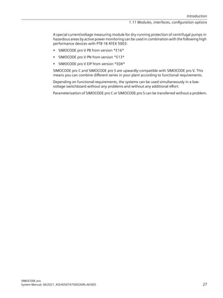


![2.3 Simplifying configuration with SIMOCODE pro
Conventional configuration without SIMOCODE pro
Individual components are used for control, monitoring and signal pre-processing. The
component and wiring requirements for this type of configuration are as follows:
• Use and wiring of overload relays, thermistor evaluation devices, current transformers and
analog/digital converters
• Wiring of the control circuit
• Connection of start / stop control devices
• The contactor must be brought into locking mode via the auxiliary switches
• Wiring of the interlocks
The following figure illustrates the conventional configuration of a direct starter:
3/
6WDUWVWRS
7KHUPLVWRU
HYDOXDWLRQ
/RFDO VWDUW
/RFDO VWRS
$XWR
0DQXDO
6ZLWFKJHDU
21
2))
2YHUORDG
7KHUPLVWRU
$XWRPDWLRQ OHYHO ,2 PRGXOH
XUUHQW
4
RSHQ
)HHGEDFN RQWURO FRPPDQGV
0DQXDO
212))
DXWRPDWLF
4
;
4
4
6
6
;
;
)
)
13(a+]9
/
/
/
1
3(
4
4
)
0
a
˽
3(
$P$
1
'
$
4 4 ) )
)
:
9
8
4
1
4 4
)
/
4
4
Figure 2-3 Conventional configuration of a motor feeder (direct starter)
Configuration with SIMOCODE pro
SIMOCODE pro only is used to perform all control, monitoring and signal pre-processing
functions.
The advantages of this configuration are as follows:
• Additional overload relays, thermistor evaluation devices, current transformers and analog/
digital converters are not necessary.
• The wiring of the control circuit (interlocking) is simplified.
Advantages/benefits/configuration with SIMOCODE pro
2.3 Simplifying configuration with SIMOCODE pro
SIMOCODE pro
System Manual, 06/2021, A5E40507475002A/RS-AE/005 33](https://image.slidesharecdn.com/systemhandbuchsimocodeproen-us-220629180849-bce542c5/85/Systemhandbuch_SIMOCODE_pro_en-US-pdf-38-320.jpg)


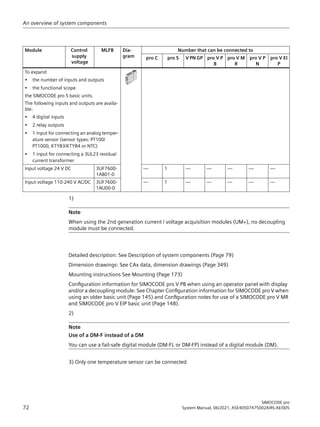
![RQWURO VWDWLRQ
/RFDO FRQWURO VWDWLRQ /@
13( a +] 9
/
/
/
1
3(
4
4
0
a
3( :
9
8
//
)
4
1/ದ
6 6
$ $
7 7
,Q ,Qದ
2XW 2XWದ
7
7
352),%86 '3
,1 ,1 9
287
/
/ದ
˽
Figure 2-4 Configuration of a load feeder (direct-on-line starter) with SIMOCODE pro
Advantages/benefits/configuration with SIMOCODE pro
2.3 Simplifying configuration with SIMOCODE pro
SIMOCODE pro
34 System Manual, 06/2021, A5E40507475002A/RS-AE/005](https://image.slidesharecdn.com/systemhandbuchsimocodeproen-us-220629180849-bce542c5/85/Systemhandbuch_SIMOCODE_pro_en-US-pdf-42-320.jpg)


![6WDUWVSRVVLEOH
2QHPRUHVWDUWRQOSRVVLEOH
1RVWDUWSRVVLEOH
2SHUDWLQJKRXUV
0RWRU!
1XPEHURIRYHUORDGWULSV
0RWRURSHUDWLQJKRXUVK@
1XPEHURIVWDUWV
3HUPLVVLEOHVWDUWV$FWXDOYDOXH
0RWRUVWRSWLPHK@
0RWRUVWRSWLPH!
(QHUJFRQVXPHGN:K@
1XPEHURISDUDPHWHUL]DWLRQV
2SHUDWLQJKRXUVEDVLFXQLWK@
7LPHU
7LPHU](https://image.slidesharecdn.com/systemhandbuchsimocodeproen-us-220629180849-bce542c5/85/Systemhandbuch_SIMOCODE_pro_en-US-pdf-129-320.jpg)


![6WDUWVSRVVLEOH
2QHPRUHVWDUWRQOSRVVLEOH
1RVWDUWSRVVLEOH
2SHUDWLQJKRXUV
0RWRU!
1XPEHURIRYHUORDGWULSV
0RWRURSHUDWLQJKRXUVK@
1XPEHURIVWDUWV
3HUPLVVLEOHVWDUWV$FWXDOYDOXH
0RWRUVWRSWLPHK@
0RWRUVWRSWLPH!
(QHUJFRQVXPHGN:K@
1XPEHURISDUDPHWHUL]DWLRQV
2SHUDWLQJKRXUVEDVLFXQLWK@
7LPHU
7LPHU](https://image.slidesharecdn.com/systemhandbuchsimocodeproen-us-220629180849-bce542c5/85/Systemhandbuch_SIMOCODE_pro_en-US-pdf-135-320.jpg)


![8.3.3.3 Read and adapt main display
To enable users speedy viewing of the measured values typically shown on their switchboard,
various profiles are stored in the operator panel with display that enable user-specific adaptation
of the standard measured values displayed in the SIMOCODE pro main display. The profile is
selected in the menu Display settings → Profiles (see Section Adapt display settings
(Page 119)).
The set current, the selected class time for the overload protection system and the use of
temperature monitoring based on thermistors or analog temperature sensors are displayed (if
programmed) at the bottom left of the main display. The submenus of the main display can be
navigated with the right-hand softkey. For motors with two speeds, the left-hand softkey can be
used to alternate between the display of the two set currents.
• IL1, IL2, IL3 [A] 1)
Shows the currents in all three phases in A.
• IL1, IL2, IL3 [%] 1)
Displays the currents in all three phases as a percentage of the set current.
• Imax [A] 1)
Shows the maximum current of all three phases in A.
• Imax [%] 1)
Displays the maximum current of all three phases as a percentage of the set current.
• Imax, Cos phi 2)
Displays the maximum current of all three phases in amps and the power factor.
• Imax, UL1-N, Cos phi, S 3)
Shows the maximum current of all three phases in amps, the phase voltage UL1 in V, the power
factor, and the apparent power in kVA.
• Imax, UL1-L2, Cos phi, S 4)
Shows the maximum current of all three phases in A, the line-to-line voltage UL1-L2 in V, the
power factor, and the apparent power in kVA.
• Imax, UL1-N, Cos phi, P 3)
Shows the maximum current of all three phases in amps, the phase voltage UL1 in V, the power
factor, and the active power in kW.
• Imax, UL1-L2, Cos phi, P 4)
Shows the maximum current of all three phases in A, the line-to-line voltage UL1-L2 in V, the
power factor, and the active power in W.
• In1/output AM1 / In1/output AM2 5)
[mA]
Shows the current value at input 1 of analog module 1 / 2 and at the output of analog module
1 / 2 in mA.
• In2/output AM1 / In2/output AM2 5)
[mA]
Shows the current value at input 2 of analog module 1 / 2 and at the output of analog module
1 / 2 in mA.
• Inputs AM 1 / inputs AM2 5)
[mA]
Description of system components
8.3 Operator panel with display
SIMOCODE pro
108 System Manual, 06/2021, A5E40507475002A/RS-AE/005](https://image.slidesharecdn.com/systemhandbuchsimocodeproen-us-220629180849-bce542c5/85/Systemhandbuch_SIMOCODE_pro_en-US-pdf-159-320.jpg)

![Permits display, for example, of a 2-byte or 4-byte value sent directly from the automation
system on the display of the switchboard or the display without units of each 2-byte and 4-byte
value in SIMOCODE pro.
• Energy consumed 2)
Note
Modified system expansion or hardware configuration
If the main display permanently fails to show measured values, this indicates that a profile has
been selected in the display settings that is no longer supported, due, for example, to a changed
system expansion or changed hardware configuration. The profile must be reselected.
1) Possible only if a current measuring module or current / voltage measuring module is used
2) Possible only if a current / voltage measuring module is used
3) Possible only if a current / voltage measuring module is used Values will only be displayed if
phase voltage is set/configured
4) Possible only if a current / voltage measuring module is used and line-to-line voltage is set/
configured
5) Possible only if the analog module is used
6) Possible only if the temperature module is used
7) Possible only if a current / voltage measuring module and temperature module are used
Values will only be displayed if phase voltage is set/configured
8.3.3.4 Display of measured values in the measured values display
The Measured Values menu item displays all current SIMOCODE pro measured values.
Depending upon the type of expansion modules used, all or only some of the values listed here
will be available. These are the most important menus by way of example:
• Imax 1)
Shows the maximum current of all three phases and can be switched between A or % of Is
• IL1, IL2, IL3 1)
Shows the currents of all three phases and can be switched between A or % of Is.
• Phase unbalance 1)
Shows the current phase unbalance as a percentage.
• UL1-N, UL2-N, UL3-N 2)
Shows all phase voltages in V.
• U L1-L2, U L2-L3, U L3-L1 3)
Shows all line-to-line voltages in V.
• Cos phi, P, S 4)
Shows the power factor (0 to 100 % or absolute, switchable using the right softkey), the
active power in kW, and the apparent power in kVA.
• Frequency [Hz] 7)
Description of system components
8.3 Operator panel with display
SIMOCODE pro
110 System Manual, 06/2021, A5E40507475002A/RS-AE/005](https://image.slidesharecdn.com/systemhandbuchsimocodeproen-us-220629180849-bce542c5/85/Systemhandbuch_SIMOCODE_pro_en-US-pdf-161-320.jpg)
![• Ground-fault current [mA]
Shows the measured value of the residual current.
• Last trip current [mA]
Shows the last measured value of the residual current.
• Analog input 1, analog input 2, analog output (for AM1) 5)
Shows the current values at both inputs and the actual value at the output of analog
module 1 and can be switched over between mA and %.
• Analog input 1, analog input 2, analog output (for AM2) 5)
Shows the actual values at both inputs and the actual value at the output of analog module 2
and can be switched over between mA and %.
• Max. temperature 6)
Shows the maximum temperature of all used sensor measuring circuits of the temperature
module 1 in °C (can be switched to °F).
• Max. temperature 6)
Shows the maximum temperature of all used sensor measuring circuits of the temperature
module 2 in °C (can be switched to °F).
• T1, T2, T3 6)
Shows the individual temperatures of all used sensor measuring circuits of the temperature
module 1 in °C (can be switched to °F).
• T1, T2, T3 6)
Shows the individual temperatures of all used sensor measuring circuits of the temperature
module 2 in °C (can be switched to °F).
• Thermal motor model
Shows the current temperature rise of the internal thermal motor model in %.
• Time to trip
Shows the estimated time to trip.
• Cooling down period
Displays the cooling down period remaining before the motor can be switched on again after
an overload trip.
• Last trip current
Shows the magnitude of the current that was measured at the moment of the overload trip,
unit of measurement can be switched between A and % of Is.
1) Possible only if a current measuring module or current / voltage measuring module is used
2) Possible only if a current / voltage measuring module is used Values will only be displayed if
phase voltage is set/configured
3) Possible only if a current / voltage measuring module is used and line-to-line voltage is set/
configured
4) Possible only if a current / voltage measuring module is used
5) Possible only if the analog module is used
6) Possible only if the temperature module is used
7) 2nd generation current / voltage measuring module necessary
Description of system components
8.3 Operator panel with display
SIMOCODE pro
System Manual, 06/2021, A5E40507475002A/RS-AE/005 111](https://image.slidesharecdn.com/systemhandbuchsimocodeproen-us-220629180849-bce542c5/85/Systemhandbuch_SIMOCODE_pro_en-US-pdf-162-320.jpg)


![Voltage measurement
• UL1-N, UL2-N, UL3-N: Displays all line-to-line voltages in V (possible only if a current / voltage
measuring module is used and the OPD is version *E04* or higher and line-to-line voltage is
set/configured).
• U L1-L2, U L2-L3, U L3-L1: Displays all line-to-line voltages in V (possible only if a current /
voltage measuring module is used, line-to-line voltage is set/configured and the OPD used is
version *E04* or higher).
Digital module 1, digital module 2
• Inputs 1 (2, 3, 4): Inputs 1, 2, 3, 4 monostable or bistable.
• Outputs 1, 2 monostable (possible only if digital module 1 is used as monostable).
Note
Display
For OPD up to product version *E03*, the display is different.
• Outputs 1, 2 bistable (possible only if digital module 1 is used as monostable or bistable).
Digital module 1 as DM-F Local
Possible only if digital module 1 is Local, an OPD as from version *E04* and a SIMOCODE pro V
(PB basic unit as from product version *E07*) is used.
• Inputs DM-F Local: Inputs IN, Start, Feedback circuit, Cascaded.
• Sensor channels DM-F Local: Sensor channels 1, 2
• Outputs DM-F Local: Outputs 1, 2, Enabling circuit.
Digital module 1 is DM-F PROFIsafe
Possible only if digital module 1 is PROFIsafe, an OPD as from version *E04* and a
SIMOCODE pro V PB / PN basic unit (PB as from product version *E07*) is used.
• Inputs DM-F PROFIsafe: Inputs 1, 2, 3, Feedback circuit.
• Outputs DM-F PROFIsafe: Outputs 1, 2, Enabling circuit.
Ground-fault module
Possible only if the ground-fault module is used.
• Ground-fault current [mA]
• Inputs
- Open circuit
- Short-circuit.
Description of system components
8.3 Operator panel with display
SIMOCODE pro
116 System Manual, 06/2021, A5E40507475002A/RS-AE/005](https://image.slidesharecdn.com/systemhandbuchsimocodeproen-us-220629180849-bce542c5/85/Systemhandbuch_SIMOCODE_pro_en-US-pdf-167-320.jpg)


![Profiles
Enables selection of the display profiles for the main display. If a defined profile is no longer
supported by SIMOCODE pro, for example, due to a changed hardware configuration, the start
display will be shown instead of the default main display:
• IL1, IL2, IL3 [A] (default)
• Imax [A]
• IL1, IL2, IL3 [%]
• Imax [%]
• Imax, Cos phi
• Imax, UL1-N, Cos phi, S
• Imax, UL1-L2, Cos phi, S
• Imax, UL1-N, Cos phi, P
• Imax, UL1-L2, Cos phi, P
• In1/output AM1 [mA] (only if analog module 1 is present and configured)
• In2/output AM1 [mA] (only if analog module 1 is present and configured)
• In1/output AM2 [mA] (only if analog module 2 is present and configured)
• In2/output AM2 [mA] (only if analog module 2 is present and configured)
• Inputs AM 1 / inputs AM2 [mA]
• Max. temp. °C/°F TM1 (only if temperature module 1 is present and configured)
• Temperatures °C/°F TM1 (only if temperature module 1 is present and configured)
• Max. temp. °C/°F TM2 (only if temperature module 2 is present and configured)
• Temperatures °C/°F TM2 (only if temperature module 2 is present and configured)
• UL1-N, UL2-N, UL3-N
• UL1-L2, UL2-L3, UL3-L1
• Imax, UL1-N, Cos phi
• Imax, UL1-L2, Cos phi
• Imax, UL1-N °C/°F (temperature display TM1! 1)
)
• Imax, UL1-L2, °C/°F 1)
(temperature display TM1! 1)
)
• Calculator 1
• Calculator 2
• Energy consumed [kWh] (only if a current / voltage measuring module is configured).
Description of system components
8.3 Operator panel with display
SIMOCODE pro
120 System Manual, 06/2021, A5E40507475002A/RS-AE/005](https://image.slidesharecdn.com/systemhandbuchsimocodeproen-us-220629180849-bce542c5/85/Systemhandbuch_SIMOCODE_pro_en-US-pdf-171-320.jpg)


![Accessories 10
Accessories overview
The following figure shows selected accessories:
0HPRUPRGXOH6,022'(SUR
,QLWLDOL]DWLRQPRGXOH
RQQHFWLQJFDEOH
$GDSWHUIRU
2SHUDWRUSDQHO
6VWHPLQWHIDFH
FRYHU
86% 3FDEOH
'RRUDGDSWHU
Figure 10-1 Accessories
USB PC cable
For device parameterization, for connecting a PC via its USB interface or serial interface to the
system interface of a basic unit.
Note
PC cable variant
For SIMOCODE pro V PN / EIP, a serial PC cable 3UF7940-0AA00-0 as from product version *E02*
or a USB PC cable USB 3UF7941-0AA00-0 can be used.
USB-to-serial adapter
For connecting an RS -232 PC cable to the USB interface of a PC.
SIMOCODE pro
System Manual, 06/2021, A5E40507475002A/RS-AE/005 163](https://image.slidesharecdn.com/systemhandbuchsimocodeproen-us-220629180849-bce542c5/85/Systemhandbuch_SIMOCODE_pro_en-US-pdf-216-320.jpg)


![Byte.Bit Setup 3UF50 -
Device-specific diag‐
nostics according to
DP standard SIMO‐
CODE DP
Byte.Bit Setup 3UF50 -
Device-specific diag‐
nostics according to
DPV1 SIMOCODE DP
Equivalent in SIMO‐
CODE pro V
13.5 Trip: Parameter fault 5 16.5 Trip: Parameter fault 5
13.6 Trip: Parameter fault 6 16.6 Trip: Parameter fault 6
13.7 Trip: Parameter fault 7 16.7 Trip: Parameter fault 7 Fault - hardware fault
basic unit
14 - 15 Number of overload
trips
Number of overload
trips
16 - 17 I of the overload trip
[% / IE)]
Last trip current
18 - 19 Operating hours [10 h] Motor operating hours
3UF50 compatibility mode
11.3 Diagram of diagnostics data
SIMOCODE pro
172 System Manual, 06/2021, A5E40507475002A/RS-AE/005](https://image.slidesharecdn.com/systemhandbuchsimocodeproen-us-220629180849-bce542c5/85/Systemhandbuch_SIMOCODE_pro_en-US-pdf-225-320.jpg)


![Figure 13-1 Connecting a PC to the basic unit
13.2.1.2 Setting the PROFIBUS DP address
Setting the PROFIBUS DP address via the addressing plug
Note
This setting cannot be made if the TEST / RESET button has been blocked.
Proceed as follows:
Table 13-3 Setting the PROFIBUS DP address via the addressing plug
Step Description
1 Set the desired valid address on the DIP switch.
The switches are numbered.
For example, address 21: Put the 16+4+1 switches in the ON position.
2 Plug the addressing plug into the system interface. The Device LED lights up yellow.
3 Briefly press the TEST / RESET button. The address you set is now stored. The Device LED flashes yellow for
approx. 3 seconds.
4 Remove the addressing plug from the system interface.
Setting the PROFIBUS DP address via SIMOCODE ES (TIA Portal)
Proceed as follows:
Table 13-4 Setting the PROFIBUS DP address via SIMOCODE ES (TIA Portal)
Step Description
1 Switch on the power supply of the basic unit.
2 Connect the USB interface of the PC/PG and the system interface of the basic unit to the Sirius USB PC cable.
It may be necessary to install a device driver for the parameterization cable when using the USB PC cable for the
first time.
3 Observe the status LED on the basic unit. The Device LED should light up green.
SIMOCODE pro can be started up.
4a Setting the address of a device configured in SIMOCODE ES (TIA Portal) (as started in steps 2 and 3):
Under Parameters → Fieldbus interface, set the Station address to the required address and then download
the parameterization to the device.
4b Setting the address of a SIMOCODE device without integration in the current project:
In the project navigator, open Online access via Online Diagnostics. Here, the device currently connected
to the serial interface can be accessed using COMx [SIRIUS PtP] → Update accessible devices. If the serial
interface COMx should indicate a protocol other than SIRIUS PtP, you can change this via the context menu
(right mouse button) → Properties. There, under Parameters → Fieldbus interface, set the Station address
to the required address and then download the change into the device again.
5 After the parameters have been transferred to the basic unit, the message confirming successful downloading
appears under Info → General in the status window.
Commissioning, service, troubleshooting
13.2 Commissioning
SIMOCODE pro
244 System Manual, 06/2021, A5E40507475002A/RS-AE/005](https://image.slidesharecdn.com/systemhandbuchsimocodeproen-us-220629180849-bce542c5/85/Systemhandbuch_SIMOCODE_pro_en-US-pdf-368-320.jpg)