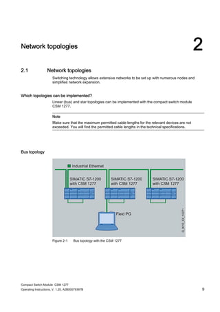
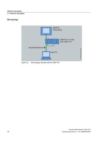
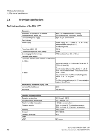
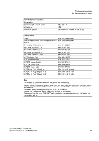
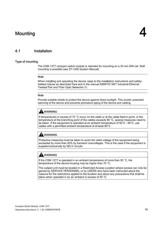
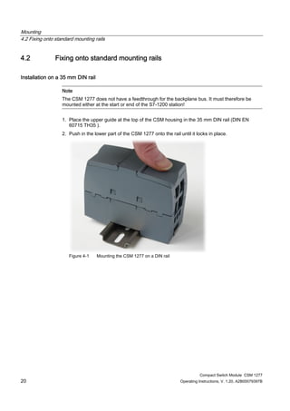
The document provides instructions for mounting and operating the CSM 1277 compact switch module, which allows for the implementation of bus or star topologies and features 4 RJ-45 ports, LED status indicators, and DIN rail mounting. It includes specifications for the switch such as its electrical characteristics, permitted cable lengths and ambient conditions. Safety notices are also provided regarding explosion hazards when used in hazardous environments.
The document provides information about SIRIUS 3RW30 and 3RW40 soft starters, including their product descriptions, functions, application planning, installation, configuration, commissioning, and technical specifications. It describes the basic principles of three-phase induction motors and how soft starters control motor starting and stopping using voltage ramping. The document also outlines safety information and guidelines for installing and working with the soft starters.
Catalogue biến tần Siemens V20 - đại lý biến tần siemens v20namtrungcompany
Giới thiệu biến tần Siemens, cách cài đặt biến tần siemens, ứng dụng của biến tần siemens, công ty TNHH Nam Trung chuyên cung cấp các loại biến tần siemens với giá tốt nhất.
The document provides information about the MP 277 HMI device, including its design, accessories, functions, configuration, commissioning, operation, maintenance and specifications. The MP 277 is an HMI device that can be used for automation applications. It has touch screen and keypad models available in 8-inch and 10-inch screen sizes. The document covers safety instructions, installation, communication setup, project transfer, operation of projects, and care of the device.
Explanation:
Provides a brief description of the cause of the alarm.
Reaction:
Describes the system reaction to the alarm, e.g. the machine stops.
Help:
Provides references to other documentation containing more detailed information on
evaluating and eliminating the cause of the alarm.
Continue program:
Specifies whether it is possible to continue the part program after the alarm occurs and has
been acknowledged.
The structure of the alarm descriptions is standardized. This ensures that all relevant
information is provided for each alarm.
SINAMICS alarms
The descriptions for the SINAMICS alarms can be found in chapter 5.
The structure of the SINAMICS alarm descriptions
The document is an instruction manual for the Emerson FB1200 Flow Computer. It describes the key features of the FB1200 including its explosion-proof enclosure, integral or external sensor options, I/O capabilities, power options, communication ports, and HMI module. It provides information on installing the device, wiring I/O, establishing communications, operating the device, and basic troubleshooting. The manual includes safety considerations and appendices with special instructions for hazardous location certifications.
The document provides safety and operating instructions for the Weapon Mounted Mini Thermal Monocular (WTM). It details potential hazards, proper battery installation, mounting procedures for helmets and weapons, operating controls and menus. Maintenance instructions include troubleshooting, inspection, cleaning and corrective procedures. The WTM allows night vision and thermal imaging with an integrated laser pointer and digital camera.
New holland mh city wheel excavator service repair manualfjskefkemms
This document provides safety instructions for operating and servicing a hydraulic excavator. It emphasizes the importance of following all safety precautions to avoid risks and ensure personal safety. Specific safety topics covered include personal protective equipment, checking the machine before starting work, safe operation practices like avoiding overhead power lines, and maintenance safety such as ensuring correct machine support and avoiding moving parts when servicing. Unauthorized or improper repairs not following the manufacturer's instructions are prohibited.
Honeywell Vista 15P Honeywell Vista-20P User GuideAlarm Grid
Alarm Grid Home Security http://www.alarmgrid.com/ has provided this pdf with the permission and courtesy of Honeywell.
Alarm Grid is a home security product and alarm monitoring company that loves its customers. We have a strong appreciation of the DIY community, and want to make sure that we not only provide the best products and services out there but we also want to make sure that resources like these Honeywell product pdfs are easily accessible so that or curious customers can find what they need when they need it.
This document provides guidelines for installing programmable logic controllers (PLCs) and related equipment in a way that minimizes electromagnetic interference (EMI). It discusses centralized vs distributed configuration, basic EMI prevention techniques like proper grounding and shielding of cables. Specific topics covered include assembly of control cabinets, routing of cables, use of equipotential bonding, power supplies, and distributed I/O installation. The document aims to help install systems that meet EMC standards.
New holland mh plus wheel excavator service repair manualkjskemmd
1. The document provides safety instructions for maintenance and repair of machines. It emphasizes the importance of following safety precautions to avoid hazards and ensure personal safety.
2. Key safety warnings are highlighted and include never attempting maintenance with the engine running or hydraulic pressure engaged. Only authorized personnel should perform repairs.
3. Personal protective equipment appropriate for the job such as helmets, gloves, protective clothing, and shoes should always be worn when working on or around machinery.
Daewoo doosan dx140 lcr 3 excavator service repair manual (serial number 1001...ufjjdjkksdekmd
The document provides maintenance instructions for an excavator model DX140LCR-3. It includes sections on safety procedures, specifications, general maintenance, maintenance of the upper structure (cabin, counterweight, fuel tank, swing bearing, swing reduction gear), lower structure and chassis (track assembly), engine and drivetrain, hydraulics (hydraulic system, accumulators, cylinders, pumps, valves), electrical system, and attachments (boom, arm, bucket). Safety is the top priority, with warnings to read all manuals, follow instructions, and ensure proper maintenance. The document provides detailed maintenance procedures and part replacements for key excavator systems.
시크 고정식 바코드스캐너 CLV69x는 처리 속도가 매우 빠르고 판독이 아주 확실하며 최고 수준의 유연성과 성능을 자랑합니다.
이 장치에 탑재된 거리 측정 기술에 기반한 자동 초점 기능 덕분에 리딩 필드 내 코드를 높이에 관계없이 판독할 수 있습니다.
진보한 SMART+ 코드 복원 기술
매개 변수 메모리가 내장된 신형 커넥터
CAN, Ethernet, D-Sub 내장(사용하는 복제 수 커넥터에 따라 다름)
실시간 자동 초점 기능으로 인한 매우 높은 피사계 심도
사용자 친화적인 통합 GUI “SOPAS ET”
트래킹 기능이 내장되어 별도 시스템 컨트롤러를 사용할 필요가 없음
유연한 분류 및 필터링 기능
내장 LED 막대 그래프(조작 필드 포함)
FEATURE
Version : Standard Density
Connection type: Depending on the cloning plug used
Reading field: Front
Scanner design: Line scanner
Focus: Auto focus (alternative: dynamic focus control)
Focus adjustment time: ≤ 20 ms
Focus trigger source: Data interface, Switching inputs
Light source: Visible red light (660 nm)
MTBF: 100,000 h
Laser class: 2 (IEC 60825-1 (2007-3))
Field of view: ≤ 60 °
Code resolution: 0.25 mm ... 1 mm
Reading distance: 500 mm ... 2,100 mm 1)
Scanning frequency: 400 Hz ... 1,200 Hz
No. of distance configurations: 8
PERFORMANCE
Bar code types : Interleaved 2 of 5, All current code types, Codabar, Code 128, Code 39, Code 93, GS1-128 / EAN 128, UPC / GTIN / EAN
Print ratio: 2:1 ... 3:1
No. of codes per scan: 1 ... 20 (Standard decoder), 1 ... 6 (SMART decoder)
No. of codes per reading interval: 1 ... 50 (auto-discriminating)
No. of characters per reading interval: 5,000
No. of multiple readings: 1 ... 100
INTERFACE
Serial (RS-232, RS-422/485): V
Remark (Serial (RS-232, RS-422/485)): Only with cloning plug D-Sub and Ethernet
Function (Serial (RS-232, RS-422/485)): Host, AUX (only RS-232)
Data transmission rate (Serial (RS-232, RS-422/485)): 300 Baud ... 500 kBaud, AUX: 57.6 kBaud (RS-232)
Ethernet: V
Remark (Ethernet) : Only with cloning plug I/O, CAN IN/OUT or CAN Redundant
Function (Ethernet) : Host, AUX
Protocol (Ethernet) : TCP/IP, EtherNet/IP, PROFINET (optional via external connection module CDF600-2), PROFINET Dual Port (optional via external connection module CDF600-2)
Data transmission rate (Ethernet): 10/100 Mbit
CAN bus : V
Function (CAN bus) : SICK CAN sensor network (Master/Slave, Multiplexer/Server)
Protocol (CAN bus) : CSN (SICK CAN Sensor Network)
Data transmission rate (CAN bus): 20 kbit/s ... 1 Mbit/s
PROFIBUS DP : V
Remark (PROFIBUS DP): Optional via external connection module (CDF600-2)
DeviceNet : V
Remark (DeviceNet): Optional via external connection module (CDM + CMF)
Control elements: 2 buttons
Switching inputs: 6 (“Sensor 1” ... “Sensor 6”)
Switching outputs: 4 (“Result 1” ... “Result 4”)
Reading pulse: Auto pulse, CAN, Switching inputs, Serial interface
Optical indicators: 6 LEDs (Ready, Result, laser, Data, CAN, LNK TX, Bar graph for displaying the reading rate percentage (10 LEDs))
Parameter storage: Integrated in cloning plug
Configuration software: SOPAS ET
>하이온아이티
주소 : 서울 금천구 가산디지털2로 165, 1304호 (백상스타타워2차)
대표번호 : 02-2038-0018 / 이메일 : hion@hionit.com
홈페이지 : http://hionsmart.com
This document provides an overview of 1FT6 synchronous motors. Key points:
- 1FT6 motors are permanently excited synchronous motors with integrated encoders that can be used with SIMODRIVE 611 and SIMOVERT MASTERDRIVES MC converters.
- Motors are available with natural cooling, forced cooling, or water cooling. Water cooling allows for higher power ratings and protection.
- Benefits include high accuracy, dynamics, efficiency, overload capability, and protection for dirty environments.
- Applications include high-performance machine tools, packaging machines, and other machinery requiring precision, flexibility and dynamics.
This document provides instructions for installing and using SICAM RTUs and SICAM AK systems. It describes the mechanical design of the mounting racks, how to install the racks, and how to install modules. It also covers system components, engineering the system, maintenance, and the licensing agreement. The document is intended for those installing, operating, and servicing SICAM AK systems.
New holland w80 btc compact wheel loader service repair manualkjskemmd
This service manual provides information on safety instructions, general safety instructions, technical specifications, and maintenance and repair procedures for compact wheel loaders models W50BTC, W60BTC, W70BTC, and W80BTC. The manual covers topics such as the engine, front and rear axles, brake system, hydraulic system, frame, steering system, electrical system, and working equipment.
This document provides an overview and instructions for setting parameters for FANUC servo motors and motors. It includes:
1. Procedures for initializing servo parameters for αiS/αiF/βiS/βiF series servo motors and setting parameters when using additional detectors or sensors.
2. Settings for large servo motors, linear motors, and synchronous built-in servo motors.
3. Information on adjusting parameters for high-speed, high-precision machining including servo tuning screens, diagnosis, and actions for alarms.
This document is a programming manual for a macro compiler and macro executor. It describes the functions of the macro compiler, which compiles macro programs into P-code, and the macro executor, which executes the compiled P-code macros. It also covers various macro functions like execution macros, conversational macros, auxiliary macros, macro variables, and macro executor functions. The manual provides definitions, limitations, and differences from previous CNC models. It aims to describe all possible and impossible operations to help users understand how to properly use the macro compiler and executor.
This document provides safety precautions for maintenance of CNC units. It contains 7 warnings related to replacing components, emphasizing the need to shut off all power, discharge static electricity, and wait for components to cool before exchange to avoid electric shock or other injuries. It also describes 5 warnings related to checking machine operation, such as verifying correct data and speeds, to prevent unexpected machine movement that could damage the machine or workpiece.
This document is a user manual for a paperless recorder. It provides instructions on installing and setting up the recorder, describes its key functions and parts, and explains how to operate the recorder. The manual is divided into chapters that cover an overview of functions, installation, names of parts, operation screens, system configurations, input/output settings, data storage, alarms, reports, communication functions, and specifications. It aims to ensure the recorder is used correctly by providing detailed information on its functions, settings, wiring methods, operation methods, and troubleshooting.
Daewoo doosan dx62 r 3 excavator service repair manual (serial number 1001 an...ufjjdjkksdekmd
The document provides instructions for maintenance of the swing bearing on excavator models DX62R-3, DX63-3, and DX85R-3. It recommends that operators consciously work to equalize usage of both ends of the excavator daily in order to extend the service life of the swing bearing. Repositioning the excavator during work shifts to alternate which end is used more can help provide more even wear. Failure to follow maintenance instructions in the manual can result in death or serious injury.
The document provides operating instructions for the OXYMAT 61 oxygen analyzer. It describes the device's area of application for continuous gas analysis, design including its communication interface and principle of operation. It also covers mounting and connecting the device, commissioning, operation including calibration and configuration, maintenance and servicing, spare parts, technical specifications, and dimension drawings. Safety information is provided throughout and qualified personnel are defined.
The document provides safety instructions for installing and operating SINAMICS G120 Power Modules. Key points include:
- Only qualified personnel should work on electrical devices after ensuring the drive system is isolated from power and cannot be restarted.
- Ground the device properly and use an appropriate protective device to prevent electric shock from ground faults or short circuits.
- Do not operate damaged or overloaded devices to prevent fire or electric shock.
- Wait 5 minutes after powering down to allow capacitors to discharge before working on the device.
- Follow all instructions to install and operate the device safely and prevent injury from electrical, mechanical, fire, and other hazards.
The assistant provides you with context-sensitive help for the current task.
�
Status bar:
The status bar displays information about the current status of the project.
�
Switch to portal view:
You can use the "Portal view" link to switch to the portal view.
�
Display of the project that is currently open:
Here, you can obtain information about which project is currently open.
�
Editors:
The editors are used to create and edit the project components.
�
Inspector window:
The inspector window displays the properties of the currently selected object.
�
Work area:
The work area provides space for
This document provides operating instructions for SIPART PS2 electropneumatic positioners with and without HART communications. It contains 15 sections that cover an introduction, general safety notes, a description of the device components and mode of operation, mounting instructions, installing optional modules, electrical and pneumatic connections, operating modes, functional safety, commissioning, parameterizing, alarm/error messages, service and maintenance, and technical data. The document provides comprehensive information for installation, setup, operation, diagnostics and maintenance of the positioner.
SITRANS P, DS III series with HART is a pressure transmitter that provides precise measurement of pressure, level, differential pressure and flow. It has a digital display and HART communication capability. The document covers safety instructions, descriptions of components and operation, installation, commissioning, maintenance and technical specifications. It is intended to ensure proper use of the transmitter in various process applications.
SIMOCODE pro is a motor management and control system for industrial applications. It consists of modular components including basic units, measuring modules, and expansion modules. The system provides protection, monitoring, control and communication functions. It can be integrated into various fieldbus systems and used in a wide range of industrial applications and areas. The manual provides detailed information on the system components, their mounting and wiring, commissioning processes, and safety guidelines for use in hazardous environments.
This document contains notes and information about programming and operating TIA Portal software versions. It includes notes on TIA Portal, STEP 7, WinCC, libraries, memory cards, virtual environments, Teamcenter Gateway, and compatibility of PLC programs from older versions. It also provides legal information, warnings, and disclaimers. The document has tables of contents to help navigate the various sections and topics.
This document provides instructions for installing, wiring, addressing, and commissioning Siemens S7-300 automation systems. It includes information on safety guidelines, selecting modules, installing racks and modules, wiring power supplies and I/O, addressing modules, and commissioning procedures.
This document provides instructions for installing, wiring, addressing, and commissioning Siemens S7-300 automation systems. It includes information on safety guidelines, selecting modules, planning networks, installing hardware, connecting wiring, assigning addresses, and steps for commissioning the PLC system.
STARTER (http://support.automation.siemens.com/WW/view/en/89254024)
• Startdrive (http://support.automation.siemens.com/WW/view/en/109738242)
4.1 Commissioning with STARTER
Connecting the Control Unit to the PC
Procedure
Proceed as follows to connect the Control Unit to the PC:
1. Connect the USB cable to the USB interface of the Control Unit.
2. Connect the other end of the USB cable to the PC.
3. Switch on the inverter power supply.
4. Start STARTER.
5
Sinamics v20 getting_started_072012_en-usphilip tony
This document provides instructions and specifications for the SINAMICS V20 Inverter, including:
- Safety precautions for installing and operating the inverter
- Guidelines for mechanical installation, electrical installation, and commissioning
- Descriptions of the built-in operator interface and parameter settings
- Technical specifications and ordering information
This document provides an overview and technical specifications for various Siemens S7-300 automation system modules, including:
1. General technical data that applies to all modules such as standards, approvals, environmental conditions, and specifications.
2. Details on power supply modules including ratings for 3 different power modules ranging from 2A to 10A.
3. Information on digital input/output modules including module overview, selection guidance, programming, diagnostics, and specifications for 16 different digital I/O modules covering a range of channel counts and voltage types.
As interface system-manual-2008-11_x-2010-09_en-usMarcio Miranda
This document provides an overview of the AS-Interface system, including its components, configuration, and operation. It describes the product portfolio, hardware setup, commissioning process, and physical/data link layers. The document also covers masters, power supplies, slaves, modules, diagnostics, and technical specifications. It aims to explain everything needed to understand and implement an AS-Interface network.
Guided
commissioning
The assistant supports you in the commis-
sioning of the CPU and connected modules.
You are guided step-by-step through the com-
missioning.
You save time during commissioning and avoid
errors.
Web server: Down-
load/upload of files
You can exchange files between the CPU and
a Web browser.
You can exchange files without STEP 7, for ex-
ample, during commissioning or maintenance.
You save time and resources.
Web server: Down-
load/upload of files
You can exchange files between the CPU and
a Web browser.
You can exchange files without STEP 7, for ex-
ample, during
Tự Động Hóa Siemens,
Catalog Thiết Bị Điện Tự Động Hóa Siemens,
Catalog Phụ Kiện Tự Động Hóa Siemens,
Catalog Tự Động Hóa Siemens,
http://dienhathe.com,
Chi tiết các sản phẩm khác của Tự Động Hóa Siemens tại https://dienhathe.com
Xem thêm các Catalog khác của Tự Động Hóa Siemens tại https://dienhathe.info
Để nhận báo giá sản phẩm Tự Động Hóa Siemens vui lòng gọi: 0907.764.966
The document provides information about the SIMATIC S7-1500/ET 200MP Analog Input Module AI 8xU/I HS. It includes sections on properties, functions, wiring, parameters, interrupts, diagnostics, technical specifications, and dimensions. The module allows high-speed analog input measurement for up to 8 channels and supports voltage or current input types. It provides interrupts, diagnostics, and parameter assignment capabilities.
This document provides an installation guide for the RUGGEDCOM RSG2488 device. It includes instructions for mounting the device, connecting power supplies, connecting communication ports, and technical specifications. The guide contains 6 chapters that cover preface information, installing the device, communication ports, and technical specifications. It provides concise instructions and diagrams for properly setting up and configuring the RSG2488.
This document provides information about the SIMATIC ET 200S distributed I/O 2 AI I 2/4WIRE HF analog electronic module. It includes sections on properties, parameters, diagnostics, analog value representation, and connecting measuring sensors. The module has 2 inputs for measuring current with ranges of ±20 mA or 4-20 mA. It supports two-wire or four-wire measuring transducers and has a resolution of 15 bits.
This manual provides information about installing and programming Siemens S7-200 Micro PLCs. It covers topics such as getting started, installing the S7-200 PLC, programming concepts and features, instructions, communicating over networks, troubleshooting, and application examples. The manual is designed for engineers and technicians working with S7-200 PLCs.
Similar to Compact switch module csm 1277 s7 1200 (20)
Este documento presenta un plano de planta de una casa con 15 habitaciones numeradas, incluyendo una cocina, comedor, sala, baño social, baño privado, habitación matrimonial y estudio. El plano también muestra detalles como un closet walk-in, patio trasero, hall de acceso, depósito, ducto de iluminación, puerta de garaje y jardinera.
Este documento establece los términos de referencia y especificaciones técnicas para el mantenimiento del sistema de circuito cerrado de televisión (CCTV) en 42 dependencias de la Empresa Pública Metropolitana de Agua Potable y Saneamiento. Incluye información sobre el alcance del servicio, la metodología de trabajo requerida, y el estado actual de los equipos CCTV en cada dependencia. El objetivo es mantener los sistemas CCTV operativos al 100% a través de mantenimientos preventivos y correctivos regulares.
Este documento establece las bases para la adquisición de estabilizadores de voltaje para su implementación en departamentos de policía en el distrito de Callao y Ventanilla. Incluye secciones sobre el registro de participantes, la presentación de consultas y observaciones, la integración de las bases y los pasos del proceso de selección como la presentación y apertura de ofertas. El objetivo es contratar la adquisición de estabilizadores de voltaje para mejorar la infraestructura eléctrica en comisarías policiales de esos distritos.
The SIMATIC S7-1200 CPU 1214C is a compact CPU for controlling small and mid-sized machines. It has 14 digital inputs, 10 relay outputs, 2 analog inputs, and communication via PROFINET. It operates on an AC supply of 85-264V at 47-63Hz and has an integrated 100KB program memory.
Este documento presenta una guía de operación e instalación para una central de alarma de incendio Bosch D7024. Explica las características del sistema incluyendo la placa de control, puntos convencionales y direccionables, gabinete, teclados, anunciadores, comunicador y usuarios. También cubre la instalación, conexiones de terminales, operación, programación, consideraciones UL, seguridad contra incendios y apéndices con especificaciones y mensajes de pantalla.
The document provides instructions for installing and operating an APC Back-UPS Pro 900 battery backup and surge protection device. It describes connecting the battery, installing software to manage automatic shutdown, connecting equipment to the different outlet types, and configuring settings like the power-saving function and sensitivity level. Safety guidelines are also provided around proper usage and potential issues.
Conozca las alarmas de las unidades smartRichard Deza
El documento describe las diferentes alarmas sonoras que puede emitir una unidad Smart-UPS de APC y su significado. La unidad Smart-UPS emite pitidos y enciende luces LED para indicar cuatro situaciones: 1) cuando cambia a modo de batería, 2) cuando está sobrecargada, 3) cuando falla la autocomprobación de baterías, y 4) cuando está en modo de batería con baja capacidad. Algunos modelos también suenan si la batería interna no está conectada. El sistema UPS puede producir chasquidos al regular autom
TIME DIVISION MULTIPLEXING TECHNIQUE FOR COMMUNICATION SYSTEMHODECEDSIET
Time Division Multiplexing (TDM) is a method of transmitting multiple signals over a single communication channel by dividing the signal into many segments, each having a very short duration of time. These time slots are then allocated to different data streams, allowing multiple signals to share the same transmission medium efficiently. TDM is widely used in telecommunications and data communication systems.
### How TDM Works
1. **Time Slots Allocation**: The core principle of TDM is to assign distinct time slots to each signal. During each time slot, the respective signal is transmitted, and then the process repeats cyclically. For example, if there are four signals to be transmitted, the TDM cycle will divide time into four slots, each assigned to one signal.
2. **Synchronization**: Synchronization is crucial in TDM systems to ensure that the signals are correctly aligned with their respective time slots. Both the transmitter and receiver must be synchronized to avoid any overlap or loss of data. This synchronization is typically maintained by a clock signal that ensures time slots are accurately aligned.
3. **Frame Structure**: TDM data is organized into frames, where each frame consists of a set of time slots. Each frame is repeated at regular intervals, ensuring continuous transmission of data streams. The frame structure helps in managing the data streams and maintaining the synchronization between the transmitter and receiver.
4. **Multiplexer and Demultiplexer**: At the transmitting end, a multiplexer combines multiple input signals into a single composite signal by assigning each signal to a specific time slot. At the receiving end, a demultiplexer separates the composite signal back into individual signals based on their respective time slots.
### Types of TDM
1. **Synchronous TDM**: In synchronous TDM, time slots are pre-assigned to each signal, regardless of whether the signal has data to transmit or not. This can lead to inefficiencies if some time slots remain empty due to the absence of data.
2. **Asynchronous TDM (or Statistical TDM)**: Asynchronous TDM addresses the inefficiencies of synchronous TDM by allocating time slots dynamically based on the presence of data. Time slots are assigned only when there is data to transmit, which optimizes the use of the communication channel.
### Applications of TDM
- **Telecommunications**: TDM is extensively used in telecommunication systems, such as in T1 and E1 lines, where multiple telephone calls are transmitted over a single line by assigning each call to a specific time slot.
- **Digital Audio and Video Broadcasting**: TDM is used in broadcasting systems to transmit multiple audio or video streams over a single channel, ensuring efficient use of bandwidth.
- **Computer Networks**: TDM is used in network protocols and systems to manage the transmission of data from multiple sources over a single network medium.
### Advantages of TDM
- **Efficient Use of Bandwidth**: TDM all
Using recycled concrete aggregates (RCA) for pavements is crucial to achieving sustainability. Implementing RCA for new pavement can minimize carbon footprint, conserve natural resources, reduce harmful emissions, and lower life cycle costs. Compared to natural aggregate (NA), RCA pavement has fewer comprehensive studies and sustainability assessments.
Embedded machine learning-based road conditions and driving behavior monitoringIJECEIAES
Car accident rates have increased in recent years, resulting in losses in human lives, properties, and other financial costs. An embedded machine learning-based system is developed to address this critical issue. The system can monitor road conditions, detect driving patterns, and identify aggressive driving behaviors. The system is based on neural networks trained on a comprehensive dataset of driving events, driving styles, and road conditions. The system effectively detects potential risks and helps mitigate the frequency and impact of accidents. The primary goal is to ensure the safety of drivers and vehicles. Collecting data involved gathering information on three key road events: normal street and normal drive, speed bumps, circular yellow speed bumps, and three aggressive driving actions: sudden start, sudden stop, and sudden entry. The gathered data is processed and analyzed using a machine learning system designed for limited power and memory devices. The developed system resulted in 91.9% accuracy, 93.6% precision, and 92% recall. The achieved inference time on an Arduino Nano 33 BLE Sense with a 32-bit CPU running at 64 MHz is 34 ms and requires 2.6 kB peak RAM and 139.9 kB program flash memory, making it suitable for resource-constrained embedded systems.
Presentation of IEEE Slovenia CIS (Computational Intelligence Society) Chapte...University of Maribor
Slides from talk presenting:
Aleš Zamuda: Presentation of IEEE Slovenia CIS (Computational Intelligence Society) Chapter and Networking.
Presentation at IcETRAN 2024 session:
"Inter-Society Networking Panel GRSS/MTT-S/CIS
Panel Session: Promoting Connection and Cooperation"
IEEE Slovenia GRSS
IEEE Serbia and Montenegro MTT-S
IEEE Slovenia CIS
11TH INTERNATIONAL CONFERENCE ON ELECTRICAL, ELECTRONIC AND COMPUTING ENGINEERING
3-6 June 2024, Niš, Serbia
KuberTENes Birthday Bash Guadalajara - K8sGPT first impressionsVictor Morales
K8sGPT is a tool that analyzes and diagnoses Kubernetes clusters. This presentation was used to share the requirements and dependencies to deploy K8sGPT in a local environment.
Electric vehicle and photovoltaic advanced roles in enhancing the financial p...IJECEIAES
Climate change's impact on the planet forced the United Nations and governments to promote green energies and electric transportation. The deployments of photovoltaic (PV) and electric vehicle (EV) systems gained stronger momentum due to their numerous advantages over fossil fuel types. The advantages go beyond sustainability to reach financial support and stability. The work in this paper introduces the hybrid system between PV and EV to support industrial and commercial plants. This paper covers the theoretical framework of the proposed hybrid system including the required equation to complete the cost analysis when PV and EV are present. In addition, the proposed design diagram which sets the priorities and requirements of the system is presented. The proposed approach allows setup to advance their power stability, especially during power outages. The presented information supports researchers and plant owners to complete the necessary analysis while promoting the deployment of clean energy. The result of a case study that represents a dairy milk farmer supports the theoretical works and highlights its advanced benefits to existing plants. The short return on investment of the proposed approach supports the paper's novelty approach for the sustainable electrical system. In addition, the proposed system allows for an isolated power setup without the need for a transmission line which enhances the safety of the electrical network
Optimizing Gradle Builds - Gradle DPE Tour Berlin 2024Sinan KOZAK
Sinan from the Delivery Hero mobile infrastructure engineering team shares a deep dive into performance acceleration with Gradle build cache optimizations. Sinan shares their journey into solving complex build-cache problems that affect Gradle builds. By understanding the challenges and solutions found in our journey, we aim to demonstrate the possibilities for faster builds. The case study reveals how overlapping outputs and cache misconfigurations led to significant increases in build times, especially as the project scaled up with numerous modules using Paparazzi tests. The journey from diagnosing to defeating cache issues offers invaluable lessons on maintaining cache integrity without sacrificing functionality.
5. Compact Switch Module CSM 1277
Operating Instructions, V. 1.20, A2B00079397B 5
Introduction 1
1.1 Preface
Overview
This section provides you with an overview of the functions of the unmanaged compact
switch module CSM 1277.
Purpose of the Commissioning Manual
This commissioning manual supports you when commissioning networks with the compact
switch module CSM 1277.
Validity of this Commissioning Manual
This commissioning manual is valid for the following device:
CSM 1277
6GK7277-1AA10-0AA0
Further documentation
The "SIMATIC NET Industrial Ethernet Twisted Pair and Fiber Optic Networks" manual
contains additional information on other SIMATIC NET products that you can operate along
with the CSM 1277 switch in an Industrial Ethernet network.
Finding information
To help you to find the information you require more quickly, the manual includes not only
the table of contents but also the following sections in the Appendix:
● Index
● Glossary
Audience
This commissioning manual is intended for personnel involved in the commissioning of
networks with the CSM 1277 compact switch module.
6. Introduction
1.1 Preface
Compact Switch Module CSM 1277
6 Operating Instructions, V. 1.20, A2B00079397B
Standards and approvals
The CSM 1277 compact switch module meets the requirements for the CE, UL, C-Tick, FM
and ATEX marks. You will find detailed information in the section "Approvals and Markings"
in this commissioning manual in the "Approvals" table.
Note
The specified approvals apply only when the corresponding mark is printed on the product.
7. Introduction
1.2 Introduction
Compact Switch Module CSM 1277
Operating Instructions, V. 1.20, A2B00079397B 7
1.2 Introduction
What is possible?
The CSM 1277 device allows the cost-effective installation of Industrial Ethernet bus or star
structures with switching functionality.
Note
It is not possible to use the CSM 1277 switch in a redundant ring because it does not support
redundancy.
Note
If the CSM 1277 switch is supplied over long 24 V power supply lines or networks, measures
are necessary to prevent interference by strong electromagnetic pulses on the supply lines.
These can result, for example, due to lightning or switching of large inductive loads.
One of the tests used to attest the immunity of the switch to electromagnetic interference
was the "surge immunity test" according to EN61000-4-5. This test requires overvoltage
protection for the power supply lines. A suitable device is, for example, the Dehn Blitzductor
VT AD 24 V type no. 918 402 or comparable protective element.
Manufacturer:
DEHN+SÖHNE GmbH+Co.KG Hans Dehn Str.1 Postfach 1640 D-92306 Neumarkt,
Germany
WARNING
When used under hazardous conditions (zone 2), the CSM 1277 switch must be installed in
an enclosure.
To comply with ATEX 95 (EN 60079-15), this enclosure must be at least IP54 in
compliance with EN 60529.
WARNING – EXPLOSION HAZARD: DO NOT DISCONNECT EQUIPMENT WHEN A
FLAMMABLE OR COMBUSTIBLE ATMOSPHERE IS PRESENT.
9. Compact Switch Module CSM 1277
Operating Instructions, V. 1.20, A2B00079397B 9
Network topologies 2
2.1 Network topologies
Switching technology allows extensive networks to be set up with numerous nodes and
simplifies network expansion.
Which topologies can be implemented?
Linear (bus) and star topologies can be implemented with the compact switch module
CSM 1277.
Note
Make sure that the maximum permitted cable lengths for the relevant devices are not
exceeded. You will find the permitted cable lengths in the technical specifications.
Bus topology
Figure 2-1 Bus topology with the CSM 1277
10. Network topologies
2.1 Network topologies
Compact Switch Module CSM 1277
10 Operating Instructions, V. 1.20, A2B00079397B
Star topology
Figure 2-2 Star topology. Example with the CSM 1277
11. Compact Switch Module CSM 1277
Operating Instructions, V. 1.20, A2B00079397B 11
3Product characteristics
3.1 Components of the product
The CSM 1277 compact switch module ships with the following:
● 3-pin terminal block (power supply)
● Operating Instructions (on the CD)
● CD
3.2 Unpacking and checking
Unpacking, checking
1. Make sure that the package is complete.
2. Check all the parts for transport damage.
WARNING
Do not use any parts that show evidence of damage!
12. Product characteristics
3.3 CSM 1277 product characteristics
Compact Switch Module CSM 1277
12 Operating Instructions, V. 1.20, A2B00079397B
3.3 CSM 1277 product characteristics
Possible attachments
The CSM 1277 has four RJ-45 jacks for the connection of end devices or other network
segments.
Figure 3-1 Compact Switch Module CSM 1277
13. Product characteristics
3.4 TP ports
Compact Switch Module CSM 1277
Operating Instructions, V. 1.20, A2B00079397B 13
3.4 TP ports
Connector pinout
On the CSM 1277, the TP ports are implemented as RJ-45 sockets with MDI-X assignment
(Medium Dependent Interface–Autocrossover) of a network component.
Figure 3-2 RJ-45 jacks
Figure 3-3 RJ-45 jack
Table 3- 1 Pin assignment of the RJ-45 jack
Pin number Assignment
Pin 8 n. c.
Pin 7 n. c.
Pin 6 TD-
Pin 5 n. c.
Pin 4 n. c.
Pin 3 TD+
Pin 2 RD-
Pin 1 RD+
14. Product characteristics
3.4 TP ports
Compact Switch Module CSM 1277
14 Operating Instructions, V. 1.20, A2B00079397B
NOTICE
TP cords or TP-XP cords with a maximum length of 10 m can be connected to the RJ-45
TP port.
With the IE FC cables and IE FC RJ-45 plug 180, an overall cable length of up to 100 m is
permitted between two devices depending on the cable type.
Autonegotiation
Autonegotiation means the automatic detection of the functionality of the port at the opposite
end. Using autonegotiation, network components or end devices can detect the functionality
available at the port of a partner device allowing automatic configuration of different types of
device. With autonegotiation, two components connected to an Ethernet segment can
exchange parameters and set themselves to match the supported communication
functionality.
Note
Devices not supporting autonegotiation must be set to 100 Mbps/ half duplex or 10 Mbps half
duplex.
Note
The CSM 1277 is a plug-and-play device that does not require settings to be made for
commissioning.
Auto polarity exchange
If the pair of receiving cables are incorrectly connected (RD+ and RD- swapped over), the
polarity is adapted automatically.
MDI /MDIX autocrossover function
The advantage of the MDI /MDIX autocrossover function is that straight-through cables can
be used throughout and crossover Ethernet cables are unnecessary. This prevents
malfunctions resulting from mismatching send and receive wires. This makes installation
much easier for the user.
Insulation between the ports
There are two port groups:
Group1: P1 and P2
Group2: P3 and P4
Between ports of different port groups, an insulation voltage of 1.5 kV is adhered to
(corresponds to IEEE802.3 Section 33.4.1.1, Environment B). For example between P1 and
P4.
15. Product characteristics
3.5 Displays
Compact Switch Module CSM 1277
Operating Instructions, V. 1.20, A2B00079397B 15
Between ports of the same group, the requirements for Environment A are met. For example
between P1 and P2.
NOTICE
Please note that the direct connection of two ports on the switch or accidental connection
over several switches causes an illegal loop. Such a loop can lead to network overload and
network failures.
3.5 Displays
Displays of the CSM 1277
Power indicator 'DIAG' (green LED)
The status of the power supply is indicated by a green LED:
Status Meaning
LED lit green Power supply is connected
LED not lit Power supply is not connected or the applied voltage is too low.
Refer to the Note in Section 4.7
Port status indicators 'P1' to 'P4' (green LEDs)
The status of the ports is indicated by four green LEDs. These are below the top panel. See
also Figure 4-4
Status Meaning
Port 1 through 4 LED lit Existing connection via port to Industrial Ethernet (LINK status)
Port 1 through 4 LED flashing Port is sending / receiving via Industrial Ethernet
Ports 1 through 4 LEDs flashing / in
sequence
Test phase during power on
16. Product characteristics
3.6 Technical specifications
Compact Switch Module CSM 1277
16 Operating Instructions, V. 1.20, A2B00079397B
3.6 Technical specifications
Technical specifications of the CSM 1277
Connectors
Attachment of end devices or network
components over twisted pair
4 x RJ-45 sockets with MDI-X pinning
10/100 Mbps (half/ full duplex), floating
Connector for power supply 3-pin plug-in terminal block
Electrical data
Power supply Power supply 24 V DC (limit: 19.2 to 28.8 V DC)
safety extra-low voltage (SELV)
Functional ground
Power loss at 24 V DC 1.6 W
Current consumption at rated voltage 70 mA
Overvoltage protection at input PTC resettable fuse (0.5 A / 60 V)
Permitted cable lengths
Connection over Industrial Ethernet FC TP cables
0 – 100 m
0 – 85 m
Industrial Ethernet FC TP standard cable with IE
FC RJ-45 plug 180
or
over Industrial Ethernet FC outlet RJ-45 with 0 -
90 m Industrial Ethernet FC TP standard cable +
10 m TP cord
Industrial Ethernet FC TP marine/trailing cable
with IE FC RJ-45 plug 180
or
0 - 75 m Industrial Ethernet FC TP marine/trailing
cable + 10 m TP cord
learnable MAC addresses / Aging Time
learnable MAC addresses 2048
Aging time 280 seconds
Permitted ambient conditions
Operating temperature 0°C through +60°C
Storage/transport temperature -40°C through +70°C
Relative humidity in operation ‹ 95% (no condensation)
Operating altitude 2000 m at max 56 °C ambient temperature
3000 m at max. 50 °C ambient temperature
Immunity EN 61000-6-2
Emission EN 61000-6-4
Degree of protection IP20
MTBF
MTBF 273 years
17. Product characteristics
3.6 Technical specifications
Compact Switch Module CSM 1277
Operating Instructions, V. 1.20, A2B00079397B 17
Permitted ambient conditions
Construction
Dimensions (W x H x D) in mm 45 x 100 x 76
Weight in g 150
Installation options 35 mm DIN rail (DIN EN 60715 TH35)
Order numbers
CSM 1277 6GK7277-1AA10-0AA0
"Industrial Ethernet TP and Fiber Optic Networks"
manual
6GK1970-1BA10-0AA0
TP Cord RJ-45/RJ-45, 0.5 m 6XV1870-3QE50
TP Cord RJ-45/RJ-45, 1 m 6XV1870-3QH10
TP Cord RJ-45/RJ-45, 2 m 6XV1870-3QH20
TP Cord RJ-45/RJ-45, 6 m 6XV1870-3QH60
TP Cord RJ-45/RJ-45, 10 m 6XV1870-3QN10
IE FC Stripping Tool 6GK1901-1GA00
IE FC blade cassettes 6GK1901-1GB00
IE FC TP standard cable 6XV1840 2AH10
IE FC TP trailing cable 6XV1840-3AH10
IE FC TP marine cable 6XV1840-4AH10
IE FC RJ-45 Plug 180 pack of 1 6GK1 901-1BB10-2AA0
IE FC RJ-45 Plug 180 pack of 10 6GK1 901-1BB10-2AB0
IE FC RJ-45 Plug 180 pack of 50 6GK1 901-1BB10-2AE0
Note
The number of connected switches influences the frame delay.
When a frame passes through the CSM 1277, it is delayed by the store and forward function
of the switch
- with a 64 byte frame length by approx. 8 µs (at 100 Mbps)
- with a 1500 byte frame length by approx. 125 µs (at 100 Mbps)
This means that the more CSM 1277 switches that a frame passes through, the higher the
frame delay will be.
19. Compact Switch Module CSM 1277
Operating Instructions, V. 1.20, A2B00079397B 19
4Mounting
4.1 Installation
Type of mounting
The CSM 1277 compact switch module is intended for mounting on a 35 mm DIN rail. Wall
mounting is possible (see S7-1200 System Manual).
Note
When installing and operating the device, keep to the installation instructions and safety-
related notices as described here and in the manual SIMATIC NET Industrial Ethernet
Twisted Pair and Fiber Optic Networks /1/.
Note
Provide suitable shade to protect the device against direct sunlight. This avoids unwanted
warming of the device and prevents premature aging of the device and cabling.
WARNING
If temperatures in excess of 70 °C occur on the cable or at the cable feed-in point, or the
temperature at the branching point of the cables exceeds 80 °C, special measures need to
be taken. If the equipment is operated at an ambient temperature of 50°C - 60°C, use
cables with a permitted ambient temperature of at least 80°C.
WARNING
Protective measures must be taken to avoid the rated voltage of the equipment being
exceeded by more than 40% by transient overvoltages. This is the case if the equipment is
supplied exclusively by SELV circuits.
WARNING
If the CSM 1277 is operated in an ambient temperature of more than 55 °C, the
temperature of the device housing may be higher than 70 °C.
The subject unit must be located in a Restricted Access Location where access can only be
gained by SERVICE PERSONNEL or by USERS who have been instructed about the
reasons for the restrictions applied to the location and about any precautions that shall be
taken when operated in an air ambient in excess of 55 °C.
20. Mounting
4.2 Fixing onto standard mounting rails
Compact Switch Module CSM 1277
20 Operating Instructions, V. 1.20, A2B00079397B
4.2 Fixing onto standard mounting rails
Installation on a 35 mm DIN rail
Note
The CSM 1277 does not have a feedthrough for the backplane bus. It must therefore be
mounted either at the start or end of the S7-1200 station!
1. Place the upper guide at the top of the CSM housing in the 35 mm DIN rail (DIN EN
60715 TH35 ).
2. Push in the lower part of the CSM 1277 onto the rail until it locks in place.
Figure 4-1 Mounting the CSM 1277 on a DIN rail
21. Mounting
4.2 Fixing onto standard mounting rails
Compact Switch Module CSM 1277
Operating Instructions, V. 1.20, A2B00079397B 21
3. Fit the connectors for the power supply. See Figure 4-5
4. Insert the terminal block into the sockets on the device. See Figure 4-4
Figure 4-2 CSM 1277 mounted on a DIN rail
Uninstalling
To remove a CSM 1277 compact switch module from the DIN rail:
1. First disconnect all connected cables.
2. Using a screwdriver, lever out the catch on the bottom of the device approximately 5 mm
while pulling the device away from the rail at the same time.
Figure 4-3 Removing the CSM 1277 from the rail
22. Mounting
4.3 Power supply
Compact Switch Module CSM 1277
22 Operating Instructions, V. 1.20, A2B00079397B
4.3 Power supply
Power supply
The power supply is connected using a 3-pin plug-in terminal block. The functional ground
can be connected to the grounded DIN rail. It does not need to be connected for problem-
free operation. The power supply is non-floating.
Figure 4-4 Connecting the power supply
Figure 4-5 Pin assignment of the terminal block
Table 4- 1 Pin assignment for the power supply
Pin number Assignment
Pin 1 L+ (24 V DC)
Pin 2 M (chassis ground)
Pin 3 Functional ground
23. Mounting
4.4 Grounding
Compact Switch Module CSM 1277
Operating Instructions, V. 1.20, A2B00079397B 23
NOTICE
The previous device CSM 1277 with order number 6GK7277-1AA00-0AA0 had a different
pin assignment of the terminal block. Pin 1: Functional grounding, Pin 2: Protective earth,
Pin 3: L+.
The supply input of the CSM is protected against polarity reversal. A reverse polarity of the
supply voltage does not cause any damage but will not result in any function either.
WARNING
The device is designed for operation with safety extra-low voltage. This means that only
safety extra-low voltages (SELV) complying with IEC 60950-1/EN60950/VDE0805 can be
connected to the power supply terminals.
The power supply unit for the device power supply must meet NEC Class 2, as described
by the National Electrical Code(r) (ANSI/NFPA 70).
The power of all connected power supply units must total the equivalent of a power source
with limited power (LPS limited power source).
Never connect the device to AC voltage.
Never operate the device with DC voltage higher than 28.8 V DC.
4.4 Grounding
35 mm DIN rail
A functional grounding can be established by connecting a cable from terminal 3 to the DIN
rail, , for example. Such a cable should be kept as short as possible. Grounding is, however,
not necessary for interference-free operation.
4.5 Twisted pair cable
Recommendation
● Cable quality at least CAT 5
● Standard cables and IE FC RJ-45 Plug 180 connectors that can be assembled in the field
for connection of the S7-1200 station to the LAN, for example over greater distances.
● Preassembled cables such as TP Cord RJ-45 0.5 m for connecting the CSM 1277 to the
CPU etc.
24. Mounting
4.6 Fitting the IE FC RJ-45 Plug 180
Compact Switch Module CSM 1277
24 Operating Instructions, V. 1.20, A2B00079397B
4.6 Fitting the IE FC RJ-45 Plug 180
IE FC RJ-45 Plug 180
The rugged node connectors with PROFINET-compliant plug-in connectors are designed for
industry and provide sure contact.
Assembly of the IE FC RJ-45 Plug 180 on an IE FC standard cable
For information on assembling an IE FC RJ-45 Plug 180 on a SIMATIC NET Industrial
Ethernet FastConnect cable, please refer to the instructions supplied with the IE FC RJ-45
Plug.
Figure 4-6 IE FC RJ-45 Plug 180
Inserting the IE FC RJ-45 Plug 180
Insert the IE FC RJ-45 Plug 180 into the twisted pair port of the CSM 1277 until it locks in
place.
Figure 4-7 Inserting the IE FC RJ-45 Plug 180
25. Mounting
4.7 Possible sources of problems and how to deal with them
Compact Switch Module CSM 1277
Operating Instructions, V. 1.20, A2B00079397B 25
Removing the IE FC RJ-45 Plug 180
Press the release button of the IE FC RJ-45 Plug 180 and pull it out of the twisted pair port of
the CSM 1277.
4.7 Possible sources of problems and how to deal with them
Fuses
Note
The CSM 1277 compact switch module has a resettable fuse / PTC. If the fuse triggers (all
LEDs are off despite correctly applied power supply), the device should be disconnected
from the power supply for approximately 30 minutes before turning it on again.
LED display when voltage is too low
If the power supply is too low, then the internal power supply will switch off causing the
DIAG-LED and all port LEDs to go off. The functionality of the CSM 1277 is no longer
available. A supply voltage of at least 19.2 V is necessary for correct operation.
LED display in case of reverse polarity of the power supply
The CSM 1277 is equipped with reverse polarity protection. A reverse polarity of the supply
voltage does not cause any damage but will not result in any function either. The DIAG-LED
and all port LEDs are off.
Device defective
If a fault develops, please send the device to your SIEMENS service center for repair.
Repairs on-site are not possible.
26. Mounting
4.7 Possible sources of problems and how to deal with them
Compact Switch Module CSM 1277
26 Operating Instructions, V. 1.20, A2B00079397B
27. Compact Switch Module CSM 1277
Operating Instructions, V. 1.20, A2B00079397B 27
Approvals and markings 5
5.1 Notes on the CE Mark
Product name
Compact switch module
SIMATIC NET CSM 1277 6GK7277-1AA10-0AA0
EMC directive
89/336/EEC "Electromagnetic Compatibility"
Area of application
The product is designed for use in an industrial environment:
Area of application Requirements
RF interference level Immunity
Industrial area EN 61000-6-4: 2007 EN 61000-6-2: 2005
Installation guidelines
The product meets the requirements if you keep to the installation instructions and safety-
related notices as described here and in the manual "SIMATIC NET Industrial Ethernet
Twisted Pair and Fiber Optic Networks" /1/ when installing and operating the device.
Conformity certificates
The EC Declaration of Conformity is available for the responsible authorities according to the
above-mentioned EC Directive at the following address:
Siemens Aktiengesellschaft
Industry Sector Industry Automation Division
Industrielle Kommunikation (I IA SC IC)
Postfach 4848
D-90026 Nürnberg
Notes for the manufacturers of machines
This product is not a machine in the sense of the EC Machinery Directive. There is therefore
no declaration of conformity relating to the EC Machinery Directive 98/37/EEC for this
product.
28. Approvals and markings
5.1 Notes on the CE Mark
Compact Switch Module CSM 1277
28 Operating Instructions, V. 1.20, A2B00079397B
If the product is part of the equipment of a machine, it must be included in the procedure for
obtaining the declaration of conformity by the manufacturer of the machine.
Certifications and approvals
c-UL-us UL 508
CSA C22.2 No. 142
FM1 FM 3611
CL.1, Div.2 GP. A.B.C.D T..
CL.1, Zone 2, GP. IIC, T..
Ta:..
C-TICK AS/NZS 2064 (Class A)
CE EN 61000-6-4,
EN 61000-6-2
ATEX Zone 21 EN60079-15:2005
EN60079-0:2006
II 3 G Ex nA II T..
KEMA 08 ATEX 0003 X
1For the temperature code "T.." or the maximum ambient temperature "Ta:..", refer to the
type plate.
WARNING
Explosion hazard!
Replacing components will impair the suitability for class I, category 2.
29. Compact Switch Module CSM 1277
Operating Instructions, V. 1.20, A2B00079397B 29
References 6
6.1 References
Sources of information and other documentation
1. SIMATIC NET Industrial Twisted Pair and Fiber-Optic Networks,
Order numbers:
6GK1970-1BA10-0AA0 German
6GK1970-1BA10-0AA1 English
6GK1970-1BA10-0AA2 French
6GK1970-1BA10-0AA4 Italian
2. PROFINET Cabling and Interconnection Technology Guideline
Can be ordered from the PROFIBUS User Organization (PNO)
6.2 Internet
Further information on the Internet
You will find additional information on SIMATIC NET products in the Internet at
http://www.automation.siemens.com/net/index_00.htm
32. Graphics
7.1 Dimension drawings
Compact Switch Module CSM 1277
32 Operating Instructions, V. 1.20, A2B00079397B
Figure 7-2 Dimension drawing, view from side
33. Compact Switch Module CSM 1277
Operating Instructions, V. 1.20, A2B00079397B 33
Glossary
Aging time
The aging time is the time after which a learned MAC address is discarded if a CSM 1277
has not received frames with this sender address during this time.
Autocrossover
Technique with which a TP port is automatically switched over between MDI and MDI-X
assignment to make a connection independent of the port assignment of the device being
attached. This means that crossover cables are not required. The autocrossover function
can only be used when the port is set to autonegotiation mode.
Autonegotiation
Procedure standardized by IEEE 802.3 in which the transmission parameters (for example
10/100 Mbps, full/half duplex) are negotiated automatically between the devices.
CRC
Cyclic Redundancy Check. A checksum used in transmission protocols to detect errors in
frames.
Multicast
A frame with a multicast address is received by all nodes prepared to receive this address.
Segment
In the Ethernet bus system, transceivers connected together over the bus cable along with
the nodes connected over patch cables form a segment. Several such segments can be
connected via repeaters. When using twisted pair and fiber-optic cables, each subsection
forms a segment.
Store and forward
An entire frame is received, its validity checked (checksum, length etc.) and then buffered.
Invalid frames are discarded, in other words, a frame is forwarded only when it is error-free.
TP
Twisted Pair
34. Glossary
Compact Switch Module CSM 1277
34 Operating Instructions, V. 1.20, A2B00079397B
TP port
Port with a TP connector (RJ-45 jack)
35. Compact Switch Module CSM 1277
Operating Instructions, V. 1.20, A2B00079397B 35
Index
A
ATEX, 6, 28
ATEX 95, 7
Autonegotiation, 14
C
CE mark, 28
Certifications and approvals, 6, 28
Conformity certificates, 27
Connecting up
High temperatures, 19
Connector pinout
TP port, 13
C-Tick mark, 6, 28
D
defective, 25
Display, 15, 25
E
Error
LED display in case of reverse polarity, 25
LED display when voltage is too low, 25
F
FM approval, 6, 28
I
Internet, 29
M
MDI /MDIX autocrossover function, 14
N
Network topology, 9
Star topology, 9, 10
P
Possible attachments, 12
R
Reduced voltage, 25
Reverse polarity, 25
U
UL approval, 6, 28