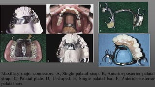
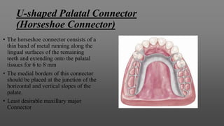
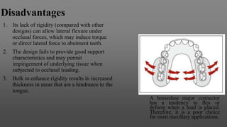
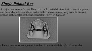
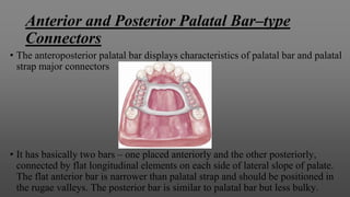
Maxillary Major Connectors
Submitted by Raghunandan Singh
Major Connectors
“The part of a removable partial denture that joins the components on one side of the
arch to those on the opposite side” (GPT 9th Edition)
Ideal Requirements:-
1. Be Rigid
2. Protect the associated soft tissues
3. Provide a means for obtaining indirect retention where indicated
4. Provide a means for placement of one or more denture bases
5. Promote patient comfort
6. It should be self cleansing and should not allow food accumulation.
Types of Maxillary Major Connectors
1. Single Palatal Strap
2. Combination anterior and posterior palatal strap–type connector
3. Palatal plate-type connector
4. U-shaped palatal connector
5. Single palatal bar
6. Anterior-posterior palatal bars
Maxillary major connectors: A, Single palatal strap. B, Anterior-posterior palatal
strap. C, Palatal plate. D, U-shaped. E, Single palatal bar. F, Anterior-posterior
palatal bars.
Design of Maxillary Major Connectors
Blatterfein in 1953, described a systematic approach to designing maxillary major
connectors. His method involves five basic steps. When using a diagnostic cast and
knowledge of the relative displaceability of the palatal tissue, including that
covering the median palatal raphe, he recommends following steps,
Step 1: Outline of primary bearing areas. The primary bearing areas are those
that will be covered by the denture base(s)
Step 2: Outline of nonbearing areas. The nonbearing areas are the lingual
gingival tissue within 5 to 6 mm of the remaining teeth, hard areas of the medial
palatal raphe (including tori), and palatal tissue posterior to the vibrating line
Step 3: Outline of connector areas. Steps 1 and 2, when completed, provide an
outline or designate areas that are available to place components of major
connectors
Step 4: Selection of connector type. Selection of the type of connector(s) is
based on four factors: mouth comfort, rigidity, location of denture bases, and
indirect retention
Step 5: Unification. After selection of the type of major connector based on
considerations in Step 4, the denture base areas and connectors are joined.
A, Diagnostic cast of partially edentulous maxillary arch. B, The palatal extent of the denture base areas are located 2 mm from the palatal surface
of the posterior teeth. C, Nonbearing areas outlined in black, which include lingual soft tissue within 5 to 6 mm of teeth, an unyielding median
palatal raphe area, and the soft palate. The space bounded by bearing and nonbearing area outlines is available for placement of the major
connector. D, The major connector selected will be rigid and noninterfering with the tongue and will cover a minimum of the palate.
Beading of the Maxillary Cast
Beading is a term used to denote the scribing of a shallow groove on the maxillary master cast
outlining the palatal major connector exclusive of rugae areas.
Framework design on master cast before preparation for duplication in refractory investment. A
shallow groove (0.5 mm) has been scribed on the outline of anterior and posterior borders of the major
connector. The anterior outline follows the valleys of rugae. Beading is readily accomplished with a
cleoid carver. A slightly rounded groove is preferred to a V-shaped groove
A, Refractory cast. Note the definitive outline of the major
connector indicated by beading lines that were transferred in
duplicating the master cast. B, The wax pattern for the major
connector is accurately executed by following the beading
lines. The major connector is confined to previously scribed
beading.
The purpose of beading is as
follows:-
1. To transfer the major
connector design to the
investment cast
2. To provide a visible finishing
line for the casting
3. To ensure intimate tissue
contact of the major
connector with selected
palatal tissue
ῼ Cast and framework showing metal margin produced by the 0.5-mm beading line scribed
on the cast. Such a margin is easily finished in the lab and provides intimate tissue contact,
preventing food from easily dislodging the prosthesis. Care should be exercised in adapting
such a beaded margin to noncompressible tissue, such as the median palatal raphe.
ῼ A, Tissue side of casting. Note slightly elevated ridges outlining
anterior, posterior, and midpalatal opening regions of this anterior-
posterior palatal strap major connector. B, Casting finished to a
demarcated outline and seated on the master cast showing intimate
adaptation.
Single Palatal Strap
A major connector of a maxillary removable
partial denture having an anterioposterior
dimension not less than 8 mm that directly or
obliquely traverses the palate; it is generally
located in the area of the second premolar and first
molar. (GPT 9th Edition)
A, This single palatal strap–type major connector is better suited
for the restoration of short-span tooth-supported bilateral
edentulous areas. It may also be used in tooth-supported unilateral
edentulous situations with provision for cross arch attachment by
extracoronal retainers or internal attachments. Width of the palatal
strap should be confined within the boundaries of supporting rests.
B, Sagittal section. Midportion of the major connector
demonstrates slight elevation to provide rigidity. Such thickness of
the major connector does not appreciably alter palatal contours.
Indications:-
1. Unilateral distal extension partial dentures (class II)
2. Tooth-supported short-span bilateral edentulous areas (class III)
Advantages:-
1. Offers great resistance to bending and twisting forces because it is located in
three planes (horizontal – palatal vault; vertical – lateral slopes of palate; sagittal
– anterior slope of palate)
2. Produces greater rigidity with less bulk of metal.
3. It can be kept thin, increasing patient comfort.
4. Retention through adhesion and cohesion is enhanced by intimate contact.
5. Also contributes some indirect retention.
Disadvantages
1. Patient may complain of excessive palatal coverage – borders should
be properly placed to avoid this.
2. Strap must avoid crossing a torus or a prominent midpalatine suture.
3. Can cause papillary hyperplasia
Combination anterior
and posterior palatal
strap–type connector
Anterior-posterior palatal strap–type major
connector. The anterior component is a flat
strap located as far posteriorly as possible to
avoid rugae coverage and tongue interference.
The anterior border of this strap should be
located just posterior to a rugae crest or in the
valley between two crests. The posterior strap
is thin, a minimum of 8 mm wide, and located
as far posteriorly as possible, yet entirely on
the hard palate. It should be located at right
angles to midline rather than diagonally.
Combination anterior and posterior palatal strap–type
connector
• Structurally, this is a rigid palatal major connector. The anterior and posterior
palatal strap combination may be used in almost any maxillary partial denture
design.
• Each strap should be at least 8 mm in width and relatively thin in cross section.
Borders of the major connector should be kept 6 mm from the free gingival
margins or should extend onto the lingual surfaces of the remaining teeth.
Palatal borders should exhibit smooth, gentle curves.
• Also sometimes referred to as Closed Horseshoe Major Connector.
Indications:-
1.When numerous teeth are to be replaced and torus is present.
2. Kennedy’s class I and II with anterior tooth replacement
Advantages:-
1. Rigid with less thickness.
2. Good palatal support.
3. Strong, L-beam effect.
Disadvantages
Interference with phonetics and
patient comfort in some cases
Palatal Plate–type Connector
Palatal major connector covering two thirds of the palate. The
anterior border follows valleys between rugae and does not extend
anteriorly to indirect retainers on the first premolars. The posterior
border is located at the junction of the hard and soft palates but
does not extend onto the soft palate. In the bilateral distal
extension situation illustrated, indirect retainers are a must to aid
in resisting horizontal rotation of the restoration. Note that
provisions have been made for a butt-type joint joining the denture
bases and framework as the denture base on each side passes
through the pterygomaxillary notch.
“A major connector of a removable partial denture
that covers a significant portion of the palatal
surface”
(GPT 9th Edition)
The palatal plate may be used in any one of three
ways
1. It may be used as a plate of varying width that
covers the area between two or more edentulous
areas
2. As a complete or partial cast plate that extends
posterior to the junction of the hard and soft
palates.
3. Or in the form of an anterior palatal connector
with a provision for extending an acrylic resin
denture base in a posterior direction
Palatal plate major connector for a Class I,
modification 1 removable partial denture. The
posterior border lies on the immovable hard palate
and crosses the midline at a right angle. Total
contact provides excellent support.
Complete coverage palatal major connector. The
posterior border terminates at the junction of the hard and
soft palates. The anterior portion, in the form of the palatal
linguoplate, is supported by positive lingual rest seats on
canines. The location of finishing lines is most important in
this type of major connector. Anteroposteriorly, they should
be parallel to a line along the center of the ridge crest and
located just lingual to an imaginary line contacting the
lingual surfaces of missing natural teeth. Alteration of the
natural palatal contour should be anticipated with its
attendant detrimental effects on speech if these contours are
not followed
A, Maxillary major connector in the form of a palatal linguoplate with provisions
for attaching the full-coverage resin denture base. B, Completed removable partial
denture with resin base. The palatal linguoplate is supported by rests occupying
lingual rest seats prepared in cast restorations on canines. This type of removable
partial denture is particularly applicable when (1) residual ridges have undergone
extreme vertical resorption, and (2) terminal abutments have suffered some bone
loss and splinting cannot be accomplished
Indications
1. Kennedy’s class I where length of span is long with anterior modification.
2. Kennedy’s class II with anterior and posterior modification spaces.
3. When opposing arch consists of a full complement of mandibular teeth
and patient has well-developed muscles of mastication, complete palate
provides the needed extra support against vertical displacement.
4. Flat, flabby ridges or shallow palatal vault, complete palate provides best
stabilization.
5. Cleft palate patients with narrow, steep palatal vault
Advantage
1. Best rigidity, support and strength.
2. If the palatal coverage is made
with acrylic resin instead of metal,
the removable partial denture is a
temporary, transitional or interim
prosthesis, used to get the patient
accustomed to complete palatal
coverage or as surgical stents
when future relining is predicted
Disadvantage
1. Adverse soft tissue reactions
because of extensive coverage
2. Problem with phonetics.
U-shaped Palatal Connector
(Horseshoe Connector)
• The horseshoe connector consists of a
thin band of metal running along the
lingual surfaces of the remaining
teeth and extending onto the palatal
tissues for 6 to 8 mm
• The medial borders of this connector
should be placed at the junction of the
horizontal and vertical slopes of the
palate.
• Least desirable maxillary major
Connector
Disadvantages
1. Its lack of rigidity (compared with other
designs) can allow lateral flexure under
occlusal forces, which may induce torque
or direct lateral force to abutment teeth.
2. The design fails to provide good support
characteristics and may permit
impingement of underlying tissue when
subjected to occlusal loading.
3. Bulk to enhance rigidity results in increased
thickness in areas that are a hindrance to the
tongue.
A horseshoe major connector
has a tendency to flex or
deform when a load is placed.
Therefore, it is a poor choice
for most maxillary applications.
Indications
• U shaped connector should be used only in those situations in which
inoperable tori extend to the posterior limit of the hard palate
Removable partial denture design that uses an objectionable
U-shaped palatal major connector. Such a connector lacks
necessary rigidity, places bulk where it is most
objectionable to the patient, and impinges on gingival tissue
lingual to remaining teeth
Single Palatal Bar
A major connector of a maxillary removable partial denture that crosses the palate
and has a characteristic shape that is half-oval anteroposteriorly with its thickest
portion at the center of the bar connector” (GPT 9th Edition)
• Palatal connector component less than 8 mm in width is referred to as a bar
Indication-
1. Interim partial denture.
2. Kennedy’s class III limited to replacing one or two teeth on each side of arch.
Disadvantage-
1. Most difficult for patient to get adjusted as
to maintain rigidity it has to be bulky.
2. Narrow anteroposterior width derives little
support from palate; hence, it should be
positively supported by rests on remaining
teeth.
3. Should be placed no further anteriorly
than second premolar position due to
tongue interference.
4. Should never be used in a distal extension
situation or in class IV.
Advantages-
Palatal bar major connectors are used
primarily in interim applications
Anterior and Posterior Palatal Bar–type
Connectors
• The anteroposterior palatal bar displays characteristics of palatal bar and palatal
strap major connectors
• It has basically two bars – one placed anteriorly and the other posteriorly,
connected by flat longitudinal elements on each side of lateral slope of palate.
The flat anterior bar is narrower than palatal strap and should be positioned in
the rugae valleys. The posterior bar is similar to palatal bar but less bulky.
Indications-
1. Patients with large inoperable tori.
2. Anterior and posterior abutments are widely separated.
3. Patients who want less palatal coverage.
4. Class II and class IV.
Advantage-
1. Rigidity.
2. Limited soft tissue coverage.
3. Strong L-beam effect contributes to
good resistance.
Disadvantage-
1. Less palatal support, hence cannot be
used when periodontal support of
remaining teeth is poor.
2. Not indicated with high narrow
palatal vault as anterior bar interferes
with phonetics.
3. Multiple borders make it
uncomfortable for patient.
Bibliography
1. Glossary of Prosthodontic Terms 9th Edition
2. McCracken’s Removable Partial Prosthodontics 12th Edition
3. Rangarajan-Padmanabhan Textbook of Prosthodontics 2nd Edition
4. Stewart’s Clinical Removable Partial Prosthodontics 4th Edition

Maxillary major connectors

  • 1.
  • 2.
    Major Connectors “The partof a removable partial denture that joins the components on one side of the arch to those on the opposite side” (GPT 9th Edition) Ideal Requirements:- 1. Be Rigid 2. Protect the associated soft tissues 3. Provide a means for obtaining indirect retention where indicated 4. Provide a means for placement of one or more denture bases 5. Promote patient comfort 6. It should be self cleansing and should not allow food accumulation.
  • 3.
    Types of MaxillaryMajor Connectors 1. Single Palatal Strap 2. Combination anterior and posterior palatal strap–type connector 3. Palatal plate-type connector 4. U-shaped palatal connector 5. Single palatal bar 6. Anterior-posterior palatal bars
  • 4.
    Maxillary major connectors:A, Single palatal strap. B, Anterior-posterior palatal strap. C, Palatal plate. D, U-shaped. E, Single palatal bar. F, Anterior-posterior palatal bars.
  • 5.
    Design of MaxillaryMajor Connectors Blatterfein in 1953, described a systematic approach to designing maxillary major connectors. His method involves five basic steps. When using a diagnostic cast and knowledge of the relative displaceability of the palatal tissue, including that covering the median palatal raphe, he recommends following steps, Step 1: Outline of primary bearing areas. The primary bearing areas are those that will be covered by the denture base(s) Step 2: Outline of nonbearing areas. The nonbearing areas are the lingual gingival tissue within 5 to 6 mm of the remaining teeth, hard areas of the medial palatal raphe (including tori), and palatal tissue posterior to the vibrating line
  • 6.
    Step 3: Outlineof connector areas. Steps 1 and 2, when completed, provide an outline or designate areas that are available to place components of major connectors Step 4: Selection of connector type. Selection of the type of connector(s) is based on four factors: mouth comfort, rigidity, location of denture bases, and indirect retention Step 5: Unification. After selection of the type of major connector based on considerations in Step 4, the denture base areas and connectors are joined.
  • 7.
    A, Diagnostic castof partially edentulous maxillary arch. B, The palatal extent of the denture base areas are located 2 mm from the palatal surface of the posterior teeth. C, Nonbearing areas outlined in black, which include lingual soft tissue within 5 to 6 mm of teeth, an unyielding median palatal raphe area, and the soft palate. The space bounded by bearing and nonbearing area outlines is available for placement of the major connector. D, The major connector selected will be rigid and noninterfering with the tongue and will cover a minimum of the palate.
  • 8.
    Beading of theMaxillary Cast Beading is a term used to denote the scribing of a shallow groove on the maxillary master cast outlining the palatal major connector exclusive of rugae areas. Framework design on master cast before preparation for duplication in refractory investment. A shallow groove (0.5 mm) has been scribed on the outline of anterior and posterior borders of the major connector. The anterior outline follows the valleys of rugae. Beading is readily accomplished with a cleoid carver. A slightly rounded groove is preferred to a V-shaped groove
  • 9.
    A, Refractory cast.Note the definitive outline of the major connector indicated by beading lines that were transferred in duplicating the master cast. B, The wax pattern for the major connector is accurately executed by following the beading lines. The major connector is confined to previously scribed beading. The purpose of beading is as follows:- 1. To transfer the major connector design to the investment cast 2. To provide a visible finishing line for the casting 3. To ensure intimate tissue contact of the major connector with selected palatal tissue
  • 10.
    ῼ Cast andframework showing metal margin produced by the 0.5-mm beading line scribed on the cast. Such a margin is easily finished in the lab and provides intimate tissue contact, preventing food from easily dislodging the prosthesis. Care should be exercised in adapting such a beaded margin to noncompressible tissue, such as the median palatal raphe.
  • 11.
    ῼ A, Tissueside of casting. Note slightly elevated ridges outlining anterior, posterior, and midpalatal opening regions of this anterior- posterior palatal strap major connector. B, Casting finished to a demarcated outline and seated on the master cast showing intimate adaptation.
  • 12.
    Single Palatal Strap Amajor connector of a maxillary removable partial denture having an anterioposterior dimension not less than 8 mm that directly or obliquely traverses the palate; it is generally located in the area of the second premolar and first molar. (GPT 9th Edition) A, This single palatal strap–type major connector is better suited for the restoration of short-span tooth-supported bilateral edentulous areas. It may also be used in tooth-supported unilateral edentulous situations with provision for cross arch attachment by extracoronal retainers or internal attachments. Width of the palatal strap should be confined within the boundaries of supporting rests. B, Sagittal section. Midportion of the major connector demonstrates slight elevation to provide rigidity. Such thickness of the major connector does not appreciably alter palatal contours.
  • 13.
    Indications:- 1. Unilateral distalextension partial dentures (class II) 2. Tooth-supported short-span bilateral edentulous areas (class III) Advantages:- 1. Offers great resistance to bending and twisting forces because it is located in three planes (horizontal – palatal vault; vertical – lateral slopes of palate; sagittal – anterior slope of palate) 2. Produces greater rigidity with less bulk of metal. 3. It can be kept thin, increasing patient comfort. 4. Retention through adhesion and cohesion is enhanced by intimate contact. 5. Also contributes some indirect retention.
  • 14.
    Disadvantages 1. Patient maycomplain of excessive palatal coverage – borders should be properly placed to avoid this. 2. Strap must avoid crossing a torus or a prominent midpalatine suture. 3. Can cause papillary hyperplasia
  • 15.
    Combination anterior and posteriorpalatal strap–type connector Anterior-posterior palatal strap–type major connector. The anterior component is a flat strap located as far posteriorly as possible to avoid rugae coverage and tongue interference. The anterior border of this strap should be located just posterior to a rugae crest or in the valley between two crests. The posterior strap is thin, a minimum of 8 mm wide, and located as far posteriorly as possible, yet entirely on the hard palate. It should be located at right angles to midline rather than diagonally.
  • 16.
    Combination anterior andposterior palatal strap–type connector • Structurally, this is a rigid palatal major connector. The anterior and posterior palatal strap combination may be used in almost any maxillary partial denture design. • Each strap should be at least 8 mm in width and relatively thin in cross section. Borders of the major connector should be kept 6 mm from the free gingival margins or should extend onto the lingual surfaces of the remaining teeth. Palatal borders should exhibit smooth, gentle curves. • Also sometimes referred to as Closed Horseshoe Major Connector.
  • 17.
    Indications:- 1.When numerous teethare to be replaced and torus is present. 2. Kennedy’s class I and II with anterior tooth replacement Advantages:- 1. Rigid with less thickness. 2. Good palatal support. 3. Strong, L-beam effect. Disadvantages Interference with phonetics and patient comfort in some cases
  • 18.
    Palatal Plate–type Connector Palatalmajor connector covering two thirds of the palate. The anterior border follows valleys between rugae and does not extend anteriorly to indirect retainers on the first premolars. The posterior border is located at the junction of the hard and soft palates but does not extend onto the soft palate. In the bilateral distal extension situation illustrated, indirect retainers are a must to aid in resisting horizontal rotation of the restoration. Note that provisions have been made for a butt-type joint joining the denture bases and framework as the denture base on each side passes through the pterygomaxillary notch. “A major connector of a removable partial denture that covers a significant portion of the palatal surface” (GPT 9th Edition) The palatal plate may be used in any one of three ways 1. It may be used as a plate of varying width that covers the area between two or more edentulous areas 2. As a complete or partial cast plate that extends posterior to the junction of the hard and soft palates. 3. Or in the form of an anterior palatal connector with a provision for extending an acrylic resin denture base in a posterior direction
  • 19.
    Palatal plate majorconnector for a Class I, modification 1 removable partial denture. The posterior border lies on the immovable hard palate and crosses the midline at a right angle. Total contact provides excellent support. Complete coverage palatal major connector. The posterior border terminates at the junction of the hard and soft palates. The anterior portion, in the form of the palatal linguoplate, is supported by positive lingual rest seats on canines. The location of finishing lines is most important in this type of major connector. Anteroposteriorly, they should be parallel to a line along the center of the ridge crest and located just lingual to an imaginary line contacting the lingual surfaces of missing natural teeth. Alteration of the natural palatal contour should be anticipated with its attendant detrimental effects on speech if these contours are not followed
  • 20.
    A, Maxillary majorconnector in the form of a palatal linguoplate with provisions for attaching the full-coverage resin denture base. B, Completed removable partial denture with resin base. The palatal linguoplate is supported by rests occupying lingual rest seats prepared in cast restorations on canines. This type of removable partial denture is particularly applicable when (1) residual ridges have undergone extreme vertical resorption, and (2) terminal abutments have suffered some bone loss and splinting cannot be accomplished
  • 21.
    Indications 1. Kennedy’s classI where length of span is long with anterior modification. 2. Kennedy’s class II with anterior and posterior modification spaces. 3. When opposing arch consists of a full complement of mandibular teeth and patient has well-developed muscles of mastication, complete palate provides the needed extra support against vertical displacement. 4. Flat, flabby ridges or shallow palatal vault, complete palate provides best stabilization. 5. Cleft palate patients with narrow, steep palatal vault
  • 22.
    Advantage 1. Best rigidity,support and strength. 2. If the palatal coverage is made with acrylic resin instead of metal, the removable partial denture is a temporary, transitional or interim prosthesis, used to get the patient accustomed to complete palatal coverage or as surgical stents when future relining is predicted Disadvantage 1. Adverse soft tissue reactions because of extensive coverage 2. Problem with phonetics.
  • 23.
    U-shaped Palatal Connector (HorseshoeConnector) • The horseshoe connector consists of a thin band of metal running along the lingual surfaces of the remaining teeth and extending onto the palatal tissues for 6 to 8 mm • The medial borders of this connector should be placed at the junction of the horizontal and vertical slopes of the palate. • Least desirable maxillary major Connector
  • 24.
    Disadvantages 1. Its lackof rigidity (compared with other designs) can allow lateral flexure under occlusal forces, which may induce torque or direct lateral force to abutment teeth. 2. The design fails to provide good support characteristics and may permit impingement of underlying tissue when subjected to occlusal loading. 3. Bulk to enhance rigidity results in increased thickness in areas that are a hindrance to the tongue. A horseshoe major connector has a tendency to flex or deform when a load is placed. Therefore, it is a poor choice for most maxillary applications.
  • 25.
    Indications • U shapedconnector should be used only in those situations in which inoperable tori extend to the posterior limit of the hard palate Removable partial denture design that uses an objectionable U-shaped palatal major connector. Such a connector lacks necessary rigidity, places bulk where it is most objectionable to the patient, and impinges on gingival tissue lingual to remaining teeth
  • 26.
    Single Palatal Bar Amajor connector of a maxillary removable partial denture that crosses the palate and has a characteristic shape that is half-oval anteroposteriorly with its thickest portion at the center of the bar connector” (GPT 9th Edition) • Palatal connector component less than 8 mm in width is referred to as a bar
  • 27.
    Indication- 1. Interim partialdenture. 2. Kennedy’s class III limited to replacing one or two teeth on each side of arch. Disadvantage- 1. Most difficult for patient to get adjusted as to maintain rigidity it has to be bulky. 2. Narrow anteroposterior width derives little support from palate; hence, it should be positively supported by rests on remaining teeth. 3. Should be placed no further anteriorly than second premolar position due to tongue interference. 4. Should never be used in a distal extension situation or in class IV. Advantages- Palatal bar major connectors are used primarily in interim applications
  • 28.
    Anterior and PosteriorPalatal Bar–type Connectors • The anteroposterior palatal bar displays characteristics of palatal bar and palatal strap major connectors • It has basically two bars – one placed anteriorly and the other posteriorly, connected by flat longitudinal elements on each side of lateral slope of palate. The flat anterior bar is narrower than palatal strap and should be positioned in the rugae valleys. The posterior bar is similar to palatal bar but less bulky.
  • 29.
    Indications- 1. Patients withlarge inoperable tori. 2. Anterior and posterior abutments are widely separated. 3. Patients who want less palatal coverage. 4. Class II and class IV. Advantage- 1. Rigidity. 2. Limited soft tissue coverage. 3. Strong L-beam effect contributes to good resistance. Disadvantage- 1. Less palatal support, hence cannot be used when periodontal support of remaining teeth is poor. 2. Not indicated with high narrow palatal vault as anterior bar interferes with phonetics. 3. Multiple borders make it uncomfortable for patient.
  • 30.
    Bibliography 1. Glossary ofProsthodontic Terms 9th Edition 2. McCracken’s Removable Partial Prosthodontics 12th Edition 3. Rangarajan-Padmanabhan Textbook of Prosthodontics 2nd Edition 4. Stewart’s Clinical Removable Partial Prosthodontics 4th Edition