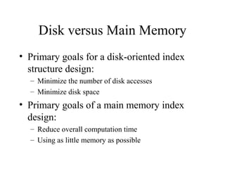
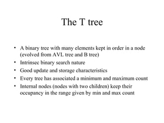
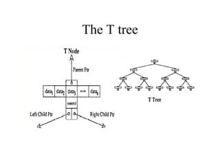
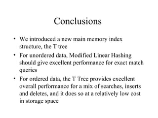
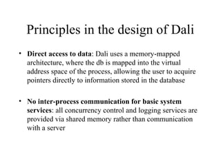
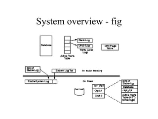
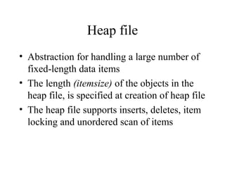
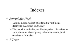
Main Memory Database Systems
Rushi
Introduction
Main Memory database system (MMDB)
• Data resides permanently on main physical
memory
• Backup copy on disk
Disk Resident database system (DRDB)
• Data resides on disk
• Data may be cached into memory for access
Main difference is that in MMDB, the primary
copy lives permanently in memory
Questions about MMDB
• Is it reasonable to assume that the entire
database fits in memory?
Yes, for some applications!
• What is the difference between a MMDB
and a DRDB with a very large cache?
In DRDB, even if all data fits in memory,
the structures and algorithms are designed
for disk access.
Differences in properties of main
memory and disk
• The access time for main memory is orders
of magnitude less than for disk storage
• Main memory is normally volatile, while
disk storage is not
• The layout of data on disk is much more
critical than the layout of data in main
memory
Impact of memory resident data
• The differences in properties of main-memory and
disk have important implications in:
– Concurrency control
– Commit processing
– Access methods
– Data representation
– Query processing
– Recovery
– Performance
Concurrency control
• Access to main memory is much faster than
disk access, so we can expect that
transactions complete more quickly in a
MM system
• Lock contention may not be as important as
it is when the data is disk resident
Commit Processing
• As protection against media failure, it is
necessary to have a backup copy and to
keep a log of transaction activity
• The need for a stable log threatens to
undermine the performance advantages that
can be achieved with memory resident data
Access Methods
• The costs to be minimized by the access
structures (indexes) are different
Data representation
• Main memory databases can take advantage
of efficient pointer following for data
representation
A study of Index Structures for
Main Memory Database
Management Systems
Tobin J. Lehman
Michael J. Carey
VLDB 1986
Disk versus Main Memory
• Primary goals for a disk-oriented index
structure design:
– Minimize the number of disk accesses
– Minimize disk space
• Primary goals of a main memory index
design:
– Reduce overall computation time
– Using as little memory as possible
Classic index structures
• Arrays:
– A: use minimal space, providing that the size is known in advance
– D: impractical for anything but a read-only environment
• AVL Trees:
– Balanced binary search tree
– The tree is kept balanced by executing rotation operations when
needed
– A: fast search
– D: poor storage utilization
Classic index structures (cont)
• B trees:
– Every node contains some ordered data items and pointers
– Good storage utilization
– Searching is reasonably fast
– Updating is also fast
Hash-based indexing
• Chained Bucket Hashing:
– Static structure, used both in memory and disk
– A: fast, if proper table size is known
– D: poor behavior in a dynamic environment
• Extendible Hashing:
– Dynamic hash table that grows with data
– A hash node contain several data items and splits in two when an
overflow occurs
– Directory grows in powers of two when a node overflows and has
reached the max depth for a particularly directory size
Hash-based indexing (cont)
• Linear Hashing:
– Uses a dynamic hash table
– Nodes are split in predefined linear order
– Buckets can be ordered sequentially, allowing the bucket address
to be calculated from a base address
– The event that triggers a node split can be based on storage
utilization
• Modified Linear Hashing:
– More oriented towards main memory
– Uses a directory which grows linearly
– Chained single items nodes
– Splitting criteria is based on average length of the hash chains
The T tree
• A binary tree with many elements kept in order in a node
(evolved from AVL tree and B tree)
• Intrinsec binary search nature
• Good update and storage characteristics
• Every tree has associated a minimum and maximum count
• Internal nodes (nodes with two children) keep their
occupancy in the range given by min and max count
The T tree
Search algorithm for T tree
• Similar to searching in a binary tree
• Algorithm
– Start at the root of the tree
– If the search value is less than the minimum value of the node
• Then search down the left subtree
• If the search value is greater than the maximum value in the node
– Then search the right subtree
– Else search the current node
The search fails when a node is searched and the item is not found, or
when a node that bounds the search value cannot be found
Insert algorithm
Insert (x):
• Search to locate the bounding node
• If a bounding node is found:
– Let a be this node
– If value fits then insert it into a and STOP
– Else
• remove min element amin from node
• Insert x
• Go to the leaf containing greatest lower bound for a and insert amin
into this leaf
Insert algorithm (cont)
• If a bounding node is not found
– Let a be the last node on the search path
– If insert value fits then insert it into the node
– Else create a new leaf with x in it
• If a new leaf was added
– For each node in the search path (from leaf to root)
• If the two subtrees heights differ by more than one, then rotate and
STOP
Delete algorithm
• (1)Search for the node that bounds the delete value; search
for the delete value within this node, reporting an error and
stopping if it is not found
• (2)If the delete will not cause an underflow then delete the
value and STOP
• Else, if this is an internal node, then delete the value and
‘borrow’ the greatest lower bound
• Else delete the element
• (3)If the node is a half-leaf and can be merged with a leaf,
do it, and go to (5)
Delete algorithm (cont)
• (4)If the current node (a leaf) is not empty, then STOP
• Else free the node and go to (5)
• (5)For every node along the path from the leaf up to the
root, if the two subtrees of the node differ in height by
more than one, then perform a rotation operation
• STOP when all nodes have been examined or a node with
even balanced has been discovered
LL Rotation
LR Rotation
Special LR Rotation
Conclusions
• We introduced a new main memory index
structure, the T tree
• For unordered data, Modified Linear Hashing
should give excellent performance for exact match
queries
• For ordered data, the T Tree provides excellent
overall performance for a mix of searches, inserts
and deletes, and it does so at a relatively low cost
in storage space
But…
• Even if the T trees have more keys in each
node, only the two end keys are actually
used for comparison
• Since for every key in node we store a
pointer to the record, and most of the time
the record pointers are not used, the space is
‘wasted’
The Architecture of the Dali
Main-Memory Storage Manager
Philip Bohannon, Daniel Lieuwen,
Rajeev Rastogi, S. Seshadri,
Avi Silberschatz, S. Sudarshan
Introduction
• Dali System is a main memory storage manager designed
to provide the persistence, availability and safety
guarantees typically expected from a disk-resident
database, while at the same time providing very high
performance
• It is intended to provide the implementor of a database
management system flexible tools for storage
management, concurrency control and recovery, without
dictating a particular storage model or precluding
optimization
Principles in the design of Dali
• Direct access to data: Dali uses a memory-mapped
architecture, where the db is mapped into the virtual
address space of the process, allowing the user to acquire
pointers directly to information stored in the database
• No inter-process communication for basic system
services: all concurrency control and logging services are
provided via shared memory rather than communication
with a server
Principles in the design of Dali (cont)
• Support for creation of fault-tolerant applications:
– Use of transactional paradigm
– Support for recovery from process and/or system failure
– Use of codewords and memory protection to help ensure the
integrity of data stored in shared memory
• Toolkit approach: for example, logging can be turned off
for data which don’t need to be persistent
• Support for multiple interface levels: low-level
components can be exposed to the user so that critical
system components can be optimized
Architecture of the Dali
• In Dali, the database consists of:
– One or more database files: stores user data
– One system database file: stores all data related to
database support
• Database files opened by a process are
directly mapped into the address space of
that process
Layers of abstraction
Dali architecture is organized to support the toolkit
approach and multiple interface levels
Storage allocation requirements
• Control data should be stored separately
form user data
• Indirection should not exist at the lowest
level
• Large objects should be stored contiguously
• Different recovery characteristics should be
available for different regions of the
database
Segments and chunks
• Segment: contiguous page-aligned units of
allocation; each database file is comprised of
segments
• Chunk: collection of segments
• Recovery characteristics are specified on a per-
chunk basis, at chunk creation
• Different alocators are available within a chunk:
– The power-of-two allocator
– The inline power-of-two allocator
– The coalescing allocator
The Page Table and Segment
Headers
• Segment header – associate info about a
segment/chunk with a physical pointer
– Allocated when segment is added to a chunk
– Can store additional info about data in segment
• Page table – maps pages to segment
headers
– Pre-allocated based on max # of pages in dbase
Transaction management in Dali
• We will present how transaction atomicity,
isolation and durability are achieved in Dali
• In Dali, data is logically organized into
regions
• Each region has a single associated lock
with exclusive and shared modes, that
guards accesses and updates to the region
Multi-level recovery (MLR)
• Provides recovery support for concurrency
based on the semantics of operations
• It permits the use of operation locks in place
of shared/exclusive region locks
• The MLR approach is to replace the low-
level physical undo log records with higher-
level logical undo log records containing
undo descriptions at the operation level
System overview - fig
System overview
• On disk:
– Two checkpoint images of the database
– An ‘anchor’ pointing to the most recent valid
checkpoint
– A single system log containing redo information, with
its tail in memory
System overview (cont)
• In memory:
– Database, mapped into the address space of each
process
– The variable end_of_stable_log, which stores a pointer
into the system log such that all records prior to the
pointer are known to have been flushed to disk
– Active Transaction Table (ATT)
– Dirty Page Table (dpt)
ATT and dpt are stored in system database and saved on
disk with each checkpoint
Transaction and Operations
• Transaction – a list of operations
– Each op. has a level Li associate with it
– Op at level Li is can consist of ops of level Li-1
– L0 are physical updates to regions
– Pre-commit – the commit record enters the
system log in memory
– Commit - commit record hits the stable storage
Logging model
• The recovery algorithm maintains separate undo
and redo logs in memory, for each transaction
• Each update generates physical undo and redo log
records
• When a transaction/operation pre-commits:
– the redo log records are appended to the system log
– the logical undo description for the operation is
included in the operation commit record in the system
log
– locks acquired by the transaction/operation are released
Logging model (cont)
• The system log is flushed to disk when a
transaction decides to commit
• Pages updated by a redo record written to disk are
marked dirty in dpt by the flushing procedure
Ping-Pong Checkpointing
• Two copies of the database image are stored
on disk and alternate checkpoints write
dirty pages to alternate copies
• Checkpointing procedure:
– Note the current end of stable log
– The contents of the in-memory ckpt_dpt are set to those
of dpt and dpt is zeroed
– The pages that were dirty in either ckpt_dpt of the last
completed checkpoint or in the current (in-memory)
ckpt_dpt are written out
Ping-Pong Checkpointing (cont)
– Checkpoint the ATT
– Flush the log and declare the checkpoint completed by
toggling cur_ckpt to point to the new checkpoint
Abort processing
• The procedure is similar with the one existent in
ARIES
• When a transaction aborts, updates/operations
described by log records in the transaction’s undo
log are undone
• New physical-redo log records are created for
each physical-undo record encountered during the
abort
Recovery
• End_of_stable_log is the ‘begin recovery
point’ for the respective checkpoint
• Restart recovery:
– Initialize the ATT with the ATT stored in checkpoint
– Initialize the transactions undo logs with the copy from
checkpoint
– Loads the database image
Recovery (cont)
– Sets dpt to zero
– Applies all redo log records and in the same time sets
the appropriate pages in dpt to dirty and maintains the
ATT consistent with the log applied so far
– The active transactions are rolled back (first all
operations at L0 that must be rolled back are rolled
back, then operations at level L1, then L2 and so on )
Post-commit operations
• These are operations which are guaranteed to be carried
out after commit of a transaction or operation, even in case
of system/process failure
• A separate post-commit log is maintained for each
transaction - every log record contains description of a
post-commit operation to be executed
• These records are appended to the system log right before
the commit record for a transaction and saved on disk
during checkpoint
Fault Tolerance
We present features for fault tolerant programming in
Dali, other than those provided directly by transaction
management.
• Handling of process death : we assume that the process
did not corrupt any system control structures
• Protection from application errors: prevent updates
which are not correctly logged from becoming reflected
in the permanent database
Detecting Process Death
• The process known as the cleanup server is responsible for
cleanup of a dead process
• When a process connects to the Dali, information about the
process are stored in the Active Process Table in system
database
• When a process terminates normally, it is deregistered
from the table
• The cleanup process periodically goes through the table
and checks if each registered process is still alive
Low level cleanup
• The cleanup process determines (by looking in the Active
Process Table) what low-level latches were held by the
crashing process
• For every latch hold by the process, it is called a cleanup
function associated with the latch
• If the function cannot repair the structure, a full system
crash is simulated
• Otherwise, go on to the next phase
Cleaning Up Transactions
• The cleanup server spawns a new process, called a cleanup
agent, to take care of any transaction still running on
behalf of the dead process
• The cleanup agent:
– Scans the transaction table
– Aborts any in-progress transaction owned by the dead process
– Executes any post-commit actions which has not been executed for
a committed transaction
Memory protection
• Application can map a database file in a special protected
mode (using mprotect system call )
• Before a page is updated, when an undo log record for the
update is generated, the page is in put in un-protected
mode (using munprotect system call)
• At the end of transaction, all unprotected pages are re-
protected
Notes: - erroneous writes are detected immediately
- system calls are expensive
Codewords
• codeword = logical parity word associated with the data
• When data is updated ‘correctly’, the codeword is updated
accordingly
• Before writing a page to disk, its contents is verified
against the codeword for that page
• If a mismatch is found, a system crash is simulated and the
database is recovered from the last checkpoint
Notes: - lower overhead is incurred during normal updates
- erroneous writes are not detected immediately
Concurrency control
• The concurrency control facilities available
in Dali include
– Latches (low-level locks for mutual
exclusion)
– Locks
Latch implementation
• Latches in Dali are implemented using the atomic
instructions supplied by the underlying architecture
Issues taken into consideration:
• Regardless of the type of atomic instructions available, the
fact that a process holds or may hold a latch must be
observable by the cleanup server
• If the target architecture provides only test-and-set or
register-memory-swap as atomic instructions, then extra
care must be taken to determine in the process did in fact
own the latch
Locking System
• Locking is usually used as the mechanism for concurrency
control at the level of a transaction
• Lock requests are made on a lock header structure which
stores a pointer to a list of locks that have been requested
by transactions
• If the lock request does not conflict with the existing locks,
then the lock is granted
• Otherwise, the requested lock is added to the list of locks
for the lock header, and is granted when the conflicting
locks are released
Collections and Indexing
• The storage allocator provides a low-level
interface for allocating and freeing data
items
• Dali also provides a higher level interface
for grouping related data items, performing
scans and associative accessing data items
Heap file
• Abstraction for handling a large number of
fixed-length data items
• The length (itemsize) of the objects in the
heap file, is specified at creation of heap file
• The heap file supports inserts, deletes, item
locking and unordered scan of items
Indexes
• Extendible Hash
– Dali includes a variant of Extendible hashing as
described in Lehman and Carey
– The decision to double the directory size is based on an
approximation of occupancy rather than on the local
overflow of a bucket
• T Trees
Higher Level Interfaces
• Two database management systems built on
Dali:
– Dali Relational Manager
– Main Memory –ODE Object Oriented Database

Main MeMory Data Base

  • 1.
    Main Memory DatabaseSystems Rushi
  • 2.
    Introduction Main Memory databasesystem (MMDB) • Data resides permanently on main physical memory • Backup copy on disk Disk Resident database system (DRDB) • Data resides on disk • Data may be cached into memory for access Main difference is that in MMDB, the primary copy lives permanently in memory
  • 3.
    Questions about MMDB •Is it reasonable to assume that the entire database fits in memory? Yes, for some applications! • What is the difference between a MMDB and a DRDB with a very large cache? In DRDB, even if all data fits in memory, the structures and algorithms are designed for disk access.
  • 4.
    Differences in propertiesof main memory and disk • The access time for main memory is orders of magnitude less than for disk storage • Main memory is normally volatile, while disk storage is not • The layout of data on disk is much more critical than the layout of data in main memory
  • 5.
    Impact of memoryresident data • The differences in properties of main-memory and disk have important implications in: – Concurrency control – Commit processing – Access methods – Data representation – Query processing – Recovery – Performance
  • 6.
    Concurrency control • Accessto main memory is much faster than disk access, so we can expect that transactions complete more quickly in a MM system • Lock contention may not be as important as it is when the data is disk resident
  • 7.
    Commit Processing • Asprotection against media failure, it is necessary to have a backup copy and to keep a log of transaction activity • The need for a stable log threatens to undermine the performance advantages that can be achieved with memory resident data
  • 8.
    Access Methods • Thecosts to be minimized by the access structures (indexes) are different
  • 9.
    Data representation • Mainmemory databases can take advantage of efficient pointer following for data representation
  • 10.
    A study ofIndex Structures for Main Memory Database Management Systems Tobin J. Lehman Michael J. Carey VLDB 1986
  • 11.
    Disk versus MainMemory • Primary goals for a disk-oriented index structure design: – Minimize the number of disk accesses – Minimize disk space • Primary goals of a main memory index design: – Reduce overall computation time – Using as little memory as possible
  • 12.
    Classic index structures •Arrays: – A: use minimal space, providing that the size is known in advance – D: impractical for anything but a read-only environment • AVL Trees: – Balanced binary search tree – The tree is kept balanced by executing rotation operations when needed – A: fast search – D: poor storage utilization
  • 13.
    Classic index structures(cont) • B trees: – Every node contains some ordered data items and pointers – Good storage utilization – Searching is reasonably fast – Updating is also fast
  • 14.
    Hash-based indexing • ChainedBucket Hashing: – Static structure, used both in memory and disk – A: fast, if proper table size is known – D: poor behavior in a dynamic environment • Extendible Hashing: – Dynamic hash table that grows with data – A hash node contain several data items and splits in two when an overflow occurs – Directory grows in powers of two when a node overflows and has reached the max depth for a particularly directory size
  • 15.
    Hash-based indexing (cont) •Linear Hashing: – Uses a dynamic hash table – Nodes are split in predefined linear order – Buckets can be ordered sequentially, allowing the bucket address to be calculated from a base address – The event that triggers a node split can be based on storage utilization • Modified Linear Hashing: – More oriented towards main memory – Uses a directory which grows linearly – Chained single items nodes – Splitting criteria is based on average length of the hash chains
  • 16.
    The T tree •A binary tree with many elements kept in order in a node (evolved from AVL tree and B tree) • Intrinsec binary search nature • Good update and storage characteristics • Every tree has associated a minimum and maximum count • Internal nodes (nodes with two children) keep their occupancy in the range given by min and max count
  • 17.
  • 18.
    Search algorithm forT tree • Similar to searching in a binary tree • Algorithm – Start at the root of the tree – If the search value is less than the minimum value of the node • Then search down the left subtree • If the search value is greater than the maximum value in the node – Then search the right subtree – Else search the current node The search fails when a node is searched and the item is not found, or when a node that bounds the search value cannot be found
  • 19.
    Insert algorithm Insert (x): •Search to locate the bounding node • If a bounding node is found: – Let a be this node – If value fits then insert it into a and STOP – Else • remove min element amin from node • Insert x • Go to the leaf containing greatest lower bound for a and insert amin into this leaf
  • 20.
    Insert algorithm (cont) •If a bounding node is not found – Let a be the last node on the search path – If insert value fits then insert it into the node – Else create a new leaf with x in it • If a new leaf was added – For each node in the search path (from leaf to root) • If the two subtrees heights differ by more than one, then rotate and STOP
  • 21.
    Delete algorithm • (1)Searchfor the node that bounds the delete value; search for the delete value within this node, reporting an error and stopping if it is not found • (2)If the delete will not cause an underflow then delete the value and STOP • Else, if this is an internal node, then delete the value and ‘borrow’ the greatest lower bound • Else delete the element • (3)If the node is a half-leaf and can be merged with a leaf, do it, and go to (5)
  • 22.
    Delete algorithm (cont) •(4)If the current node (a leaf) is not empty, then STOP • Else free the node and go to (5) • (5)For every node along the path from the leaf up to the root, if the two subtrees of the node differ in height by more than one, then perform a rotation operation • STOP when all nodes have been examined or a node with even balanced has been discovered
  • 23.
  • 24.
  • 25.
  • 26.
    Conclusions • We introduceda new main memory index structure, the T tree • For unordered data, Modified Linear Hashing should give excellent performance for exact match queries • For ordered data, the T Tree provides excellent overall performance for a mix of searches, inserts and deletes, and it does so at a relatively low cost in storage space
  • 27.
    But… • Even ifthe T trees have more keys in each node, only the two end keys are actually used for comparison • Since for every key in node we store a pointer to the record, and most of the time the record pointers are not used, the space is ‘wasted’
  • 28.
    The Architecture ofthe Dali Main-Memory Storage Manager Philip Bohannon, Daniel Lieuwen, Rajeev Rastogi, S. Seshadri, Avi Silberschatz, S. Sudarshan
  • 29.
    Introduction • Dali Systemis a main memory storage manager designed to provide the persistence, availability and safety guarantees typically expected from a disk-resident database, while at the same time providing very high performance • It is intended to provide the implementor of a database management system flexible tools for storage management, concurrency control and recovery, without dictating a particular storage model or precluding optimization
  • 30.
    Principles in thedesign of Dali • Direct access to data: Dali uses a memory-mapped architecture, where the db is mapped into the virtual address space of the process, allowing the user to acquire pointers directly to information stored in the database • No inter-process communication for basic system services: all concurrency control and logging services are provided via shared memory rather than communication with a server
  • 31.
    Principles in thedesign of Dali (cont) • Support for creation of fault-tolerant applications: – Use of transactional paradigm – Support for recovery from process and/or system failure – Use of codewords and memory protection to help ensure the integrity of data stored in shared memory • Toolkit approach: for example, logging can be turned off for data which don’t need to be persistent • Support for multiple interface levels: low-level components can be exposed to the user so that critical system components can be optimized
  • 32.
    Architecture of theDali • In Dali, the database consists of: – One or more database files: stores user data – One system database file: stores all data related to database support • Database files opened by a process are directly mapped into the address space of that process
  • 33.
    Layers of abstraction Daliarchitecture is organized to support the toolkit approach and multiple interface levels
  • 34.
    Storage allocation requirements •Control data should be stored separately form user data • Indirection should not exist at the lowest level • Large objects should be stored contiguously • Different recovery characteristics should be available for different regions of the database
  • 35.
    Segments and chunks •Segment: contiguous page-aligned units of allocation; each database file is comprised of segments • Chunk: collection of segments • Recovery characteristics are specified on a per- chunk basis, at chunk creation • Different alocators are available within a chunk: – The power-of-two allocator – The inline power-of-two allocator – The coalescing allocator
  • 36.
    The Page Tableand Segment Headers • Segment header – associate info about a segment/chunk with a physical pointer – Allocated when segment is added to a chunk – Can store additional info about data in segment • Page table – maps pages to segment headers – Pre-allocated based on max # of pages in dbase
  • 37.
    Transaction management inDali • We will present how transaction atomicity, isolation and durability are achieved in Dali • In Dali, data is logically organized into regions • Each region has a single associated lock with exclusive and shared modes, that guards accesses and updates to the region
  • 38.
    Multi-level recovery (MLR) •Provides recovery support for concurrency based on the semantics of operations • It permits the use of operation locks in place of shared/exclusive region locks • The MLR approach is to replace the low- level physical undo log records with higher- level logical undo log records containing undo descriptions at the operation level
  • 39.
  • 40.
    System overview • Ondisk: – Two checkpoint images of the database – An ‘anchor’ pointing to the most recent valid checkpoint – A single system log containing redo information, with its tail in memory
  • 41.
    System overview (cont) •In memory: – Database, mapped into the address space of each process – The variable end_of_stable_log, which stores a pointer into the system log such that all records prior to the pointer are known to have been flushed to disk – Active Transaction Table (ATT) – Dirty Page Table (dpt) ATT and dpt are stored in system database and saved on disk with each checkpoint
  • 42.
    Transaction and Operations •Transaction – a list of operations – Each op. has a level Li associate with it – Op at level Li is can consist of ops of level Li-1 – L0 are physical updates to regions – Pre-commit – the commit record enters the system log in memory – Commit - commit record hits the stable storage
  • 43.
    Logging model • Therecovery algorithm maintains separate undo and redo logs in memory, for each transaction • Each update generates physical undo and redo log records • When a transaction/operation pre-commits: – the redo log records are appended to the system log – the logical undo description for the operation is included in the operation commit record in the system log – locks acquired by the transaction/operation are released
  • 44.
    Logging model (cont) •The system log is flushed to disk when a transaction decides to commit • Pages updated by a redo record written to disk are marked dirty in dpt by the flushing procedure
  • 45.
    Ping-Pong Checkpointing • Twocopies of the database image are stored on disk and alternate checkpoints write dirty pages to alternate copies • Checkpointing procedure: – Note the current end of stable log – The contents of the in-memory ckpt_dpt are set to those of dpt and dpt is zeroed – The pages that were dirty in either ckpt_dpt of the last completed checkpoint or in the current (in-memory) ckpt_dpt are written out
  • 46.
    Ping-Pong Checkpointing (cont) –Checkpoint the ATT – Flush the log and declare the checkpoint completed by toggling cur_ckpt to point to the new checkpoint
  • 47.
    Abort processing • Theprocedure is similar with the one existent in ARIES • When a transaction aborts, updates/operations described by log records in the transaction’s undo log are undone • New physical-redo log records are created for each physical-undo record encountered during the abort
  • 48.
    Recovery • End_of_stable_log isthe ‘begin recovery point’ for the respective checkpoint • Restart recovery: – Initialize the ATT with the ATT stored in checkpoint – Initialize the transactions undo logs with the copy from checkpoint – Loads the database image
  • 49.
    Recovery (cont) – Setsdpt to zero – Applies all redo log records and in the same time sets the appropriate pages in dpt to dirty and maintains the ATT consistent with the log applied so far – The active transactions are rolled back (first all operations at L0 that must be rolled back are rolled back, then operations at level L1, then L2 and so on )
  • 50.
    Post-commit operations • Theseare operations which are guaranteed to be carried out after commit of a transaction or operation, even in case of system/process failure • A separate post-commit log is maintained for each transaction - every log record contains description of a post-commit operation to be executed • These records are appended to the system log right before the commit record for a transaction and saved on disk during checkpoint
  • 51.
    Fault Tolerance We presentfeatures for fault tolerant programming in Dali, other than those provided directly by transaction management. • Handling of process death : we assume that the process did not corrupt any system control structures • Protection from application errors: prevent updates which are not correctly logged from becoming reflected in the permanent database
  • 52.
    Detecting Process Death •The process known as the cleanup server is responsible for cleanup of a dead process • When a process connects to the Dali, information about the process are stored in the Active Process Table in system database • When a process terminates normally, it is deregistered from the table • The cleanup process periodically goes through the table and checks if each registered process is still alive
  • 53.
    Low level cleanup •The cleanup process determines (by looking in the Active Process Table) what low-level latches were held by the crashing process • For every latch hold by the process, it is called a cleanup function associated with the latch • If the function cannot repair the structure, a full system crash is simulated • Otherwise, go on to the next phase
  • 54.
    Cleaning Up Transactions •The cleanup server spawns a new process, called a cleanup agent, to take care of any transaction still running on behalf of the dead process • The cleanup agent: – Scans the transaction table – Aborts any in-progress transaction owned by the dead process – Executes any post-commit actions which has not been executed for a committed transaction
  • 55.
    Memory protection • Applicationcan map a database file in a special protected mode (using mprotect system call ) • Before a page is updated, when an undo log record for the update is generated, the page is in put in un-protected mode (using munprotect system call) • At the end of transaction, all unprotected pages are re- protected Notes: - erroneous writes are detected immediately - system calls are expensive
  • 56.
    Codewords • codeword =logical parity word associated with the data • When data is updated ‘correctly’, the codeword is updated accordingly • Before writing a page to disk, its contents is verified against the codeword for that page • If a mismatch is found, a system crash is simulated and the database is recovered from the last checkpoint Notes: - lower overhead is incurred during normal updates - erroneous writes are not detected immediately
  • 57.
    Concurrency control • Theconcurrency control facilities available in Dali include – Latches (low-level locks for mutual exclusion) – Locks
  • 58.
    Latch implementation • Latchesin Dali are implemented using the atomic instructions supplied by the underlying architecture Issues taken into consideration: • Regardless of the type of atomic instructions available, the fact that a process holds or may hold a latch must be observable by the cleanup server • If the target architecture provides only test-and-set or register-memory-swap as atomic instructions, then extra care must be taken to determine in the process did in fact own the latch
  • 59.
    Locking System • Lockingis usually used as the mechanism for concurrency control at the level of a transaction • Lock requests are made on a lock header structure which stores a pointer to a list of locks that have been requested by transactions • If the lock request does not conflict with the existing locks, then the lock is granted • Otherwise, the requested lock is added to the list of locks for the lock header, and is granted when the conflicting locks are released
  • 60.
    Collections and Indexing •The storage allocator provides a low-level interface for allocating and freeing data items • Dali also provides a higher level interface for grouping related data items, performing scans and associative accessing data items
  • 61.
    Heap file • Abstractionfor handling a large number of fixed-length data items • The length (itemsize) of the objects in the heap file, is specified at creation of heap file • The heap file supports inserts, deletes, item locking and unordered scan of items
  • 62.
    Indexes • Extendible Hash –Dali includes a variant of Extendible hashing as described in Lehman and Carey – The decision to double the directory size is based on an approximation of occupancy rather than on the local overflow of a bucket • T Trees
  • 63.
    Higher Level Interfaces •Two database management systems built on Dali: – Dali Relational Manager – Main Memory –ODE Object Oriented Database

Editor's Notes

  • #18 Proceedings of the Twelfth International Conference on Very Large Data Bases, Kyoto, August, 1986
  • #24 Proceedings of the Twelfth International Conference on Very Large Data Bases, Kyoto, August, 1986
  • #25 Proceedings of the Twelfth International Conference on Very Large Data Bases, Kyoto, August, 1986
  • #26 Proceedings of the Twelfth International Conference on Very Large Data Bases, Kyoto, August, 1986