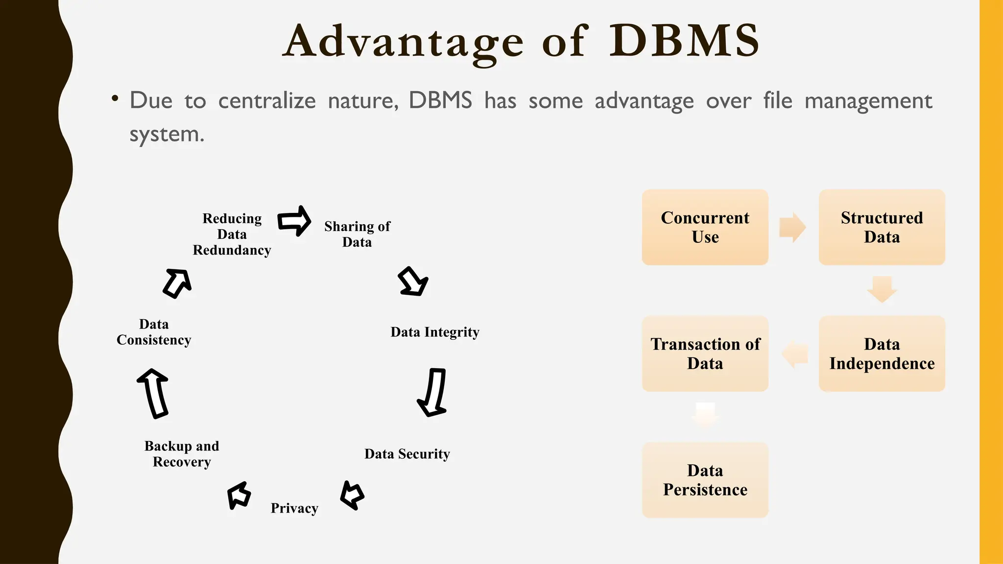
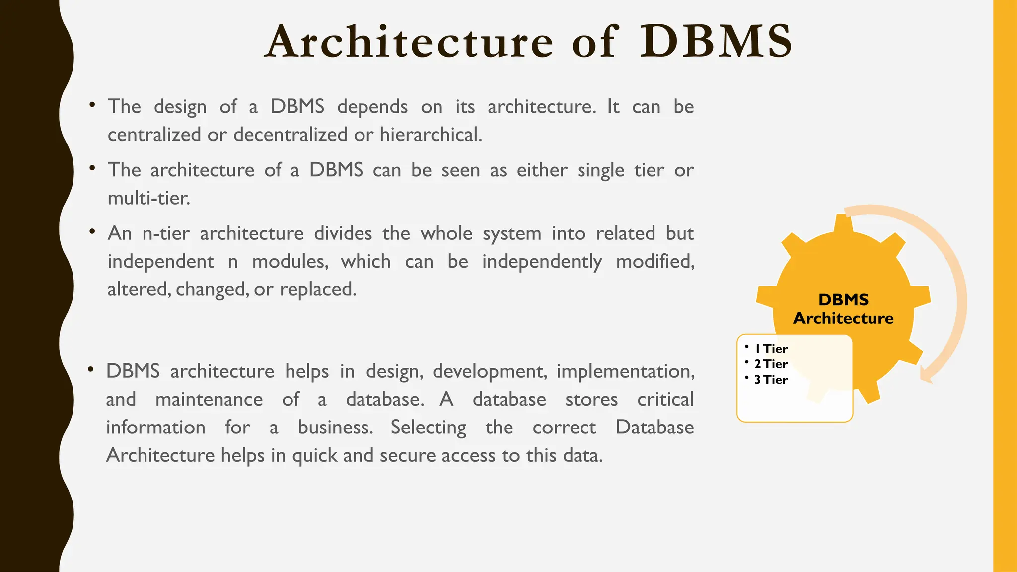
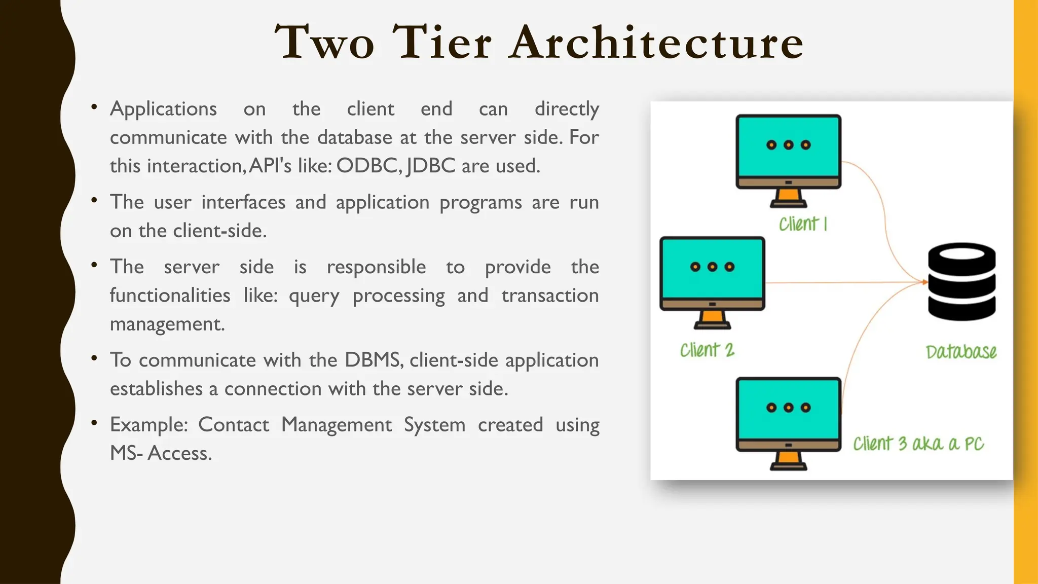
DBMS: UNIT 1
Content, Objective & Outcome
• Basic Concepts: Introduction to DBMS, File system vs DBMS, Advantages of
database systems, Database System architecture, Data models, Schemas and
instances, Data independence, Functions of DBA and designer, Entities and
attributes, Entity types, Key attributes, Relationships, Defining the E-R diagram of
database.
• Course Objective: To understand fundamental knowledge of file system, database
concepts and use of relational database.
• Course Outcome: Compare file system and DBMS and explain how DBMS is
better than traditional File Processing Systems.
Data & Information
• What is Data?
• Data is a distinct piece of information that is gathered and translated for some purpose. If data
is not formatted in a specific way, it does not valuable to computers or humans. Data can be
available in terms of different forms, such as bits and bytes stored in electronic memory,
numbers or text on pieces of paper, or facts stored in a person's mind. Since the invention of
computers, people have used the word data to mean computer information, and this
information is transmitted or stored.
• Data is raw fact or figures or entity.
THERE ARE DIFFERENT KINDS OF DATA; SUCH ARE AS
FOLLOWS:
Data is stored on the computer in binary form (zero or one), which can be processed, created, saved, and
stored digitally.
• Sound
• Video
• Single character
• Number (integer or floating-point)
• Picture
• Boolean (true or false)
• Text (string)
PROCESSED DATA
• Data processing occurs when data is collected and translated into
usable informationis called information
• The purpose of data processing is to generate the information required for
carrying out the business activities.
Database
• A database is basically a set of data and it contains interrelated data. The
database contains set of algorithm and rules through which data can be stored
in it in a systematic manner. So, all the data fields must be related to each
other.
• A database is a logically coherent collection of data with some inherent
meaning, representing some aspect of real world. It is designed built and
populated with data for a specific purpose.
• A database consists of 4 elements:
(i) Data (ii) Relationship (iii) Constraints (iv) Schema
Database Management System
• The software used for the management, maintenance and retrieval of the data stored in
the database.A DBMS is a collection of interrelated data and a set of program to access
those data.
• It is also used to organize the data in the form of a table, schema, views, and reports, etc.
• For example: The college Database organizes the data about the admin, staff, students
and faculty etc.
• Using the database, you can easily retrieve, insert, and delete the information.
• Collection of database and DBMS software.A database system consist of 4 major components:
(i) Data (ii) Hardware (iii) Software (iv) Database users
DBMS ALLOWS USERS THE FOLLOWING TASKS:
• Data Definition: It is used for creation, modification, and removal of definition that defines
the organization of data in the database.
• Data Updation : It is used for the insertion, modification, and deletion of the actual data in
the database.
• Data Retrieval: It is used to retrieve the data from the database which can be used by
applications for various purposes.
CHARACTERISTICS OF DBMS
• It uses a digital repository established on a server to store and manage the information.
• DBMS contains automatic backup and recovery procedures.
• It can reduce the complex relationship between data.
• It is used to support manipulation and processing of data.
• It is used to provide security of data.
• It can view the database from different viewpoints according to the requirements of the user.
ADVANTAGES OF DBMS
• Controls database redundancy: It can control data redundancy because it stores all the
data in one single database file and that recorded data is placed in the database.
• Data sharing: In DBMS, the authorized users of an organization can share the data among
multiple users.
• Easily Maintenance: It can be easily maintainable due to the centralized nature of the
database system.
• Reduce time: It reduces development time and maintenance need.
• Backup: It provides backup and recovery subsystems which create automatic backup of data
from hardware and software failures and restores the data if required.
• multiple user interface: It provides different types of user interfaces like graphical user
interfaces, application program interfaces
DBMS vs File System
DBMS File System
DBMS is a collection of data and user is not required to
write the procedures for managing the database.
File system is a collection of data. Any management
with the file system, user has to write the procedures
DBMS provides an abstract view of data that hides the
details.
File system gives the details of the data representation
and Storage of data.
DBMS is efficient to use since there are wide varieties of
sophisticated techniques to store and retrieve the data.
In File system storing and retrieving of data cannot be
done efficiently.
DBMS takes care of Concurrent access using some form
of locking.
Concurrent access to the data in the file system has many
problems like
a. Reading the file while other deleting some
information, updating some information
DBMS has crash recovery mechanism DBMS protects
user from the effects of system failures.
File system doesn’t provide crash recovery mechanism.
Eg. While we are entering some data into the file if
System crashes then content of the file is lost.
DBMS has a good protection mechanism. Protecting a file under file system is very difficult.
FILE SYSTEM APPROACH
• File based systems were an early attempt to computerize the manual system. It is also called a
traditional based approach in which a decentralized approach was taken where each
department stored and controlled its own data with the help of a data processing specialist.
The main role of a data processing specialist was to create the necessary computer file
structures, and also manage the data within structures and design some application programs
that create reports based on file data.
FILE SYSTEM APPROACH
DBMS:
• A database approach is a well-organized collection of data that are related in a meaningful way
which can be accessed by different users but stored only once in a system.The various
operations performed by the DBMS system are: Insertion, deletion, selection, sorting etc.
DBMS:
Evolution of DBMS
1960 •
DBMS
came
into
existence
in
1960
by
Charles.
Integrated
data
store
which
is
also
called
as
the
first
general-purpose
DBMS
1960 •
Again
in
1960
IBM
brought
IMS-Information
management
system.
1970 •
In
1970
Edgar
Codd
at
IBM
came
with
a
new
database
called
RDBMS
1980 •
In
1980
then
came
SQL
Architecture-
Structure
Query
Language
1980 •
In
1980
to
1990
there
were
advances
in
DBMS,
e.g.
DB2,
ORACLE.
Advantage of DBMS
• Due to centralize nature, DBMS has some advantage over file management
system.
Sharing of
Data
Data Integrity
Data Security
Privacy
Backup and
Recovery
Data
Consistency
Reducing
Data
Redundancy
Concurrent
Use
Structured
Data
Data
Independence
Transaction of
Data
Data
Persistence
Architecture of DBMS
• The design of a DBMS depends on its architecture. It can be
centralized or decentralized or hierarchical.
• The architecture of a DBMS can be seen as either single tier or
multi-tier.
• An n-tier architecture divides the whole system into related but
independent n modules, which can be independently modified,
altered, changed, or replaced.
• DBMS architecture helps in design, development, implementation,
and maintenance of a database. A database stores critical
information for a business. Selecting the correct Database
Architecture helps in quick and secure access to this data.
DBMS
Architecture
• 1Tier
• 2Tier
• 3Tier
Single Tier Architecture
• In this architecture, the database is directly available to the user. It means the user can directly
communicate with the database and uses it.
• Any changes done here will directly be done on the database itself. It doesn't provide a handy tool
for end users.
• The 1-Tier architecture is used for development of the local application, where programmers can
directly communicate with the database for the quick response.
Two Tier Architecture
• Applications on the client end can directly
communicate with the database at the server side. For
this interaction,API's like: ODBC, JDBC are used.
• The user interfaces and application programs are run
on the client-side.
• The server side is responsible to provide the
functionalities like: query processing and transaction
management.
• To communicate with the DBMS, client-side application
establishes a connection with the server side.
• Example: Contact Management System created using
MS- Access.
Three Tier Architecture
• The 3-Tier architecture contains another layer between the client and server. In this architecture, client
can't directly communicate with the server.
• The application on the client-end interacts with an application server which further communicates with
the database system.
• End user has no idea about the existence of the database beyond the application server.The database
also has no idea about any other user beyond the application.
The goal of Three teir architecture is:
• To separate the user applications and physical database
• Proposed to support DBMS characteristics
• Program-data independence
• Support of multiple views of the data
Three Tier Architecture
Database (Data) Tier The database resides along with its query processing languages. We also
−
have the relations that define the data and their constraints at this level.
Application (Middle)Tier At this tier reside the application server and the programs that access
−
the database. For a user, it presents an abstracted view of the database. Hence, the application layer
sits in the middle and acts as a mediator between the end-user and the database.
User (Presentation) Tier End-users operate on this tier and they know nothing about any
−
existence of the database beyond this layer. Multiple views of the database can be provided by the
application. All views are generated by applications that reside in the application tier.
DBMS Architecture Component
Database Users
Application programmers:
• Application programmers are computer professionals who write application programs.
Application programmers can choose from many tools to develop user interfaces.
• Rapid application development (RAD) tools are tools that enable an application programmer
to construct forms and reports without writing a program.
Sophisticated users:
• Sophisticated users interact with the system without writing programs. Instead, they form
their requests in a database query language.
Specialized users:
• These are also sophisticated users, but they write special database application programs.They
are the developers who develop the complex programs to the requirement.
Naïve users:
• Naive users are unsophisticated users who interact with the system by invoking one of the
application programs that have been written previously.
Database Administrator:
• Coordinates all the activities of the database system.The database administrator has a good
understanding of the enterprise’s information resources and needs.
Application
Programmer
Sophisticated
User
Specialized
User
Naïve User
Database
Administrator
Database Models
A Database model defines the logical design and structure of a database and defines how data will be
stored, accessed and updated in a database management system.
Data
Models
Relational
Hierarchical
Network
Object
Oriented
Object
Relational
E-R Model
Relational Model
• Data is organized in two-dimensional tables and the relationship is maintained by storing a common
field.
• This model was introduced by E.F Codd in 1970, and since then it has been the most widely used
database model.
• Data is stored in tables called relations.
• Relations can be normalized.
• In normalized relations, values saved are atomic values.
• Each row in a relation contains a unique value.
• Each column in a relation contains values from a same
domain.
Hierarchical Model
• Organizes data into a tree-like-structure, with a single root, to which all the other data is linked.The
hierarchy starts from the Root data, and expands like a tree, adding child nodes to the parent nodes.
• In this model, a child node will only have a single parent node.
• This model efficiently describes many real-world relationships like index of a book, recipes etc.
• In hierarchical model, data is organized into tree-like structure with one one-to-many relationship
between two different types of data, for example, one department can have many courses, many
professors and of-course many students.
Network Model
• The network model builds on the hierarchical model by allowing many-to-many relationships
between linked records, implying multiple parent records.
• Based on mathematical set theory, the model is constructed with sets of related records.
• Each set consists of one owner or parent record and one or more member or child records.
• A record can be a member or child in multiple sets, allowing this model to convey complex
relationships.
Object Oriented Model
• Defines a database as a collection of objects, or
reusable software elements, with associated features
and methods. There are several kinds of object-
oriented databases:
A multimedia database incorporates media, such as
images, that could not be stored in a relational database.
A hypertext database allows any object to link to any
other object. It’s useful for organizing lots of disparate
data, but it’s not ideal for numerical analysis.
• The object-oriented database model is the best known
post-relational database model, since it incorporates
tables, but isn’t limited to tables. Such models are also
known as hybrid database models.
Object Relational Model
• An Object relational model is a combination of a Object oriented database model and a Relational
database model. So, it supports objects, classes, inheritance etc. just like Object Oriented models and
has support for data types, tabular structures etc. like Relational data model.
• One of the major goals of Object relational data model is to close the gap between relational
databases and the object oriented practices frequently used in many programming languages such as
C++, C#, Java etc.
Entity Relational Model
• Entity-Relationship (ER) Model is based on the notion of real-world entities and relationships among
them.While formulating real-world scenario into the database model, the ER Model creates entity
set, relationship set, general attributes and constraints.
• This model captures the relationships between real-world entities much like the network model, but
it isn’t as directly tied to the physical structure of the database. Instead, it’s often used for designing a
database conceptually.
Database Schema
• A database schema is the skeleton
structure that represents the logical view
of the entire database.
• It defines how the data is organized and
how the relations among them are
associated.
• It formulates all the constraints that are to
be applied on the data.
• It’s the database designers who design the
schema to help programmers understand
the database and make it useful.
Logical Schema
Physical
Schema
View
Schema
Database Schema
• Physical Schema: The design of a database at
physical level is called physical schema, how the data
stored in blocks of storage is described at this level.
• Logical Schema: Design of database at logical level
is called logical schema. Programmers and database
administrators work at this level, at this level data can
be described as certain types of data records gets
stored in data structures, however the internal details
such as implementation of data structure is hidden at
this level (available at physical level).
• View Schema: Design of database at view level is
called view schema.This generally describes end user
interaction with database systems.
Database Instances
• Database schema is the skeleton of database. It is designed when the database
doesn't exist at all.
• Once the database is operational, it is very difficult to make any changes to it.
• A database schema does not contain any data or information.
• A database instance is a state of operational database with data at any given time.
• It contains a snapshot of the database.
• Database instances tend to change with time.
• A DBMS ensures that its every instance (state) is in a valid state, by diligently
following all the validations, constraints, and conditions that the database designers
have imposed.
Data Independence
• Need of Data Independence: A database system normally contains a lot of data in addition to
users’ data.
• For example, it stores data about data, known as metadata, to locate and retrieve data easily.
• It is rather difficult to modify or update a set of metadata once it is stored in the database.
• But as a DBMS expands, it needs to change over time to satisfy the requirements of the users.
• If the entire data is dependent, it would become a tedious and highly complex job.
• Data Independence is defined as a property of DBMS that helps you to change the Database schema
at one level of a database system without requiring to change the schema at the next higher level.
• Data independence helps you to keep data separated from all programs that make use of it.
• You can use this stored data for computing and presentation.
• In many systems, data independence is an essential function for components of the system.
Data Independence
Types of Data Independence
Logical Data Independence
Physical Data Independence
Levels of Database
Physical/Internal
Conceptual
External
Data Independence
Physical Data Independence
• Helps to separate conceptual levels from the internal/physical levels. It allows user to provide a logical
description of the database without the need to specify physical structures.
• User can easily change the physical storage structures or devices with an effect on the conceptual
schema. Any change done would be absorbed by the mapping between the conceptual and internal
levels.
Examples of changes under Physical Data Independence
• Using a new storage device like Hard Drive or Magnetic Tapes
• Modifying the file organization technique in the Database
• Switching to different data structures
• Changing the access method
• Modifying indexes
• Changes to compression techniques or hashing algorithms
• Change of Location of Database from say C drive to D Drive
Logical Data Independence
Logical Data Independence is the ability to change the conceptual scheme without changing
• External views
• External API or programs
Any change made will be absorbed by the mapping between external and conceptual levels.
Examples of changes under Logical Data Independence
• Add/Modify/Delete a new attribute, entity or relationship is possible without a rewrite of existing
application programs
• Merging two records into one
• Breaking an existing record into two or more records
Logical Data Independence
Logical Data Independence Physical Data Independence
Logical Data Independence is mainly concerned with the
structure or changing the data definition.
Mainly concerned with the storage of the data.
It is difficult as the retrieving of data is mainly dependent on the
logical structure of data.
It is easy to retrieve.
Compared to Physical independence it is difficult to achieve
logical data independence.
Compared to Logical Independence it is easy to achieve physical
data independence.
You need to make changes in the Application program if new
fields are added or deleted from the database.
A change in the physical level usually does not need change at
the Application program level.
Modification at the logical levels is significant whenever the
logical structures of the database are changed.
Modifications made at the internal levels may or may not be
needed to improve the performance of the structure.
Concerned with conceptual schema Concerned with internal schema
Example:Add/Modify/Delete a new attribute Example: change in compression techniques, hashing algorithms,
storage devices, etc
Database Administrator
A database administrator (DBA) is a specialized computer systems administrator who maintains a
successful database environment by directing or performing all related activities to keep the data secure.
The top responsibility of a DBA professional is to maintain data integrity. This means the DBA will
ensure that data is secure from unauthorized access but is available to users.
E-R Model/Diagram
An Entity–relationship model (ER model) describes the structure of a
database with the help of a diagram, which is known as Entity Relationship
Diagram (ER Diagram).
An ER model is a design or blueprint of a database that can later be
implemented as a database.
An ER diagram shows the relationship among entity sets.An entity set is a
group of similar entities and these entities can have attributes.
In terms of DBMS, an entity is a table or attribute of a table in database,
so by showing relationship among tables and their attributes, ER diagram
shows the complete logical structure of a database.
Components of E-R Diagram
Entities
Attributes
Relationships
Entity in E-R Model/Diagram
A real-world thing either living or non-living that is easily recognizable and non-recognizable.
It is anything in the enterprise that is to be represented in our database.
It may be a physical thing or simply a fact about the enterprise or an event that happens in the real
world.
The characteristics of entities are must have an attribute, and a unique key.
Every entity is made up of some 'attributes' which represent that entity.
An entity set is a group of similar kind of entities. It may contain entities with attribute sharing similar
values. Entities are represented by their properties, which also called attributes.All attributes have their
separate values. For example, a student entity may have a name, age, class, as attributes.
Example of Entity:
Person: Employee, Student, Patient Place: Store, Building
Object: Machine, product, and Car Event: Sale, Registration, Renewal
Concept:Account, Course
TYPES OF ATTRIBUTES IN ER MODEL
• An attribute is a property or characteristic of an entity.An entity may contain any number of
attributes. One of the attributes is considered as the primary key. In an Entity-Relation model,
attributes are represented in an elliptical shape.
• Example: Student has attributes like name, age, roll number, and many more.To uniquely identify
the student, we use the primary key as a roll number as it is not repeated.Attributes can also
be subdivided into another set of attributes.
• There are six such types of attributes: Simple, Composite, Single-valued, Multi-valued, and
Derived attribute. One more attribute is their, i.e. Complex Attribute, this is the rarely used
attribute.
SIMPLE ATTRIBUTE :
• Simple attribute :
• An attribute that cannot be further subdivided into components is a simple attribute.
Example: The roll number of a student, the id number of an employee.
• Composite attribute :
• An attribute that can be split into components is a composite attribute.
• Example: The address can be further split into house number, street number, city, state,
country, and pin code, the name can also be split into first name middle name, and last name.
SINGLE-VALUED ATTRIBUTE :
• Single-valued attribute :
• The attribute which takes up only a single value for each entity instance is a single-valued
attribute.
• Example: The age of a student.
• Multi-valued attribute :
• The attribute which takes up more than a single value for each entity instance is a multi-valued
attribute.
• Example: Phone number of a student: Landline and mobile.
DERIVED ATTRIBUTE
• Derived attribute :
• An attribute that can be derived from other attributes is derived attributes.
• Example: Total and average marks of a student.
• Complex attribute :
• Those attributes, which can be formed by the nesting of composite and multi-valued
attributes, are called “Complex Attributes“.These attributes are rarely used in
DBMS(DataBase Management System).That’s why they are not so popular.
STORED ATTRIBUTE:
• Stored attribute:
• The stored attribute are those attribute which doesn’t require any type of further update since they are stored in the database.
• Example: DOB(Date of birth) is the stored attribute.
• Key attribute:
• Key attributes are those attributes that can uniquely identify the entity in the entity set.
• Example: Roll-No is the key attribute because it can uniquely identify the student.
• Representation:
• Complex attributes are the nesting of two or more composite and multi-valued attributes.Therefore, these multi-valued and
composite attributes are called ‘Components’ of complex attributes.
Attribute in E-R Model/Diagram
Attributes are the properties which define the entity type. In ER diagram, attribute is represented by an
oval.
• Can not be
divided further
• Contact No.
Simple
• Can be divided
further
• Name,Address
Composite
• Value derived
from other
attribute
• DOB-Age
Derived
• Have more
than 1 value
• Hobby, Contact
Multivalued
Attribute in E-R Model/Diagram
Relationship Type & Relationship Set
A relationship type represents the association between entity types. For example, ‘Enrolled in’ is a
relationship type that exists between entity type Student and Course.
In ER diagram, relationship type is represented by a diamond and connecting the entities with lines.
Degree of relationship set:
The number of different entity sets participating in a relationship set is called as degree of a relationship
set.
Unary
Binary
N-ary
Relationship Type & Relationship Set
Unary Relationship: When there is only ONE entity set participating in a relation, the relationship is
called as unary relationship. Example, one person is married to only one person.
Binary Relationship: When there are TWO entities set participating in a relation, the relationship is
called as binary relationship. Example, Student is enrolled in Course.
N-ary Relationship: When there are n entities set participating in a relation, the relationship is called
as n-ary relationship.
ONE-TO-ONE RELATIONSHIP
• One-to-One Relationship
• Such a relationship exists when each record of one table is related to only one record of the
other table.
• For example, If there are two entities ‘Person’ (Id, Name,Age,Address)and
‘Passport’(Passport_id, Passport_no). So, each person can have only one passport and each
passport belongs to only one person.
ONE-TO-ONE RELATIONSHIP
• Such a relationship is not very common. However, such a relationship is used for security purposes. In the
above example, we can easily store the passport id in the ‘Person’ table only. But, we make another table
for the ‘Passport’ because Passport number may be sensitive data and it should be hidden from certain
users. So, by making a separate table we provide extra security that only certain database users can see it.
ONE-TO-MANY OR MANY-TO-ONE RELATIONSHIP
• Such a relationship exists when each record of one table can be related to one or more than one
record of the other table.This relationship is the most common relationship found.A one-to-many
relationship can also be said as a many-to-one relationship depending upon the way we view it.
• For example, If there are two entity type ‘Customer’ and ‘Account’ then each ‘Customer’ can
have more than one ‘Account’ but each ‘Account’ is held by only one ‘Customer’. In this example,
we can say that each Customer is associated with many Account. So, it is a one-to-many
relationship. But, if we see it the other way i.e many Account is associated with one Customer then
we can say that it is a many-to-one relationship.
ONE-TO-MANY OR MANY-TO-ONE
RELATIONSHIP
MANY-TO-MANY RELATIONSHIP
• Such a relationship exists when each record of the first table can be related to one or more
than one record of the second table and a single record of the second table can be related to
one or more than one record of the first table.A many-to-many relationship can be seen as a
two one-to-many relationship which is linked by a 'linking table' or 'associate table'.The linking
table links two tables by having fields which are the primary key of the other two tables.We
can understand this with the following example.
• Example: If there are two entity type ‘Customer’ and ‘Product’ then each customer can buy
more than one product and a product can be bought by many different customers.
MANY-TO-MANY RELATIONSHIP
Relationship Type & Relationship Set
Cardinality: The number of times an entity of an entity set participates in a relationship set is known
as cardinality.
One to One: When each entity in each entity set can take part only once in the relationship, the
cardinality is one to one.
One to Many: One entity from entity set X can be associated with multiple entities of entity setY, but
an entity from entity setY can be associated with at least one entity.
Relationship Type & Relationship Set
Many to One: When entities in one entity set
can take part only once in the relationship set
and entities in other entity set can take part
more than once in the relationship set
Many to Many: When entities in all entity sets
can take part more than once in the relationship
cardinality is many to many.
Recursive & Ternary Relationship
When an Entity is related with itself it is known as
Recursive Relationship.
Relationship of degree three is called Ternary
relationship.
A Ternary relationship involves three entities. In such
relationships we always consider two entities
together and then look upon the third.
A Company produces many Products/ each product is
produced by exactly one company.
A Company operates in only one Sector / each sector has
many companies operating in it.
Considering the above two rules or relationships, we see
that although the complete relationship involves three
entities, but we are looking at two entities at a time.
Participation Constraints
Participation Constraint is applied on the entity participating in the relationship set.
Total Participation: Each entity in the entity set must participate in the relationship. If each student
must enroll in a course, the participation of student will be total.Total participation is shown by double
line in ER diagram.
Partial Participation: The entity in the entity set may or may NOT participate in the relationship. If
some courses are not enrolled by any of the student, the participation of course will be partial.
The diagram depicts the ‘Enrolled in’ relationship set with Student Entity set having total
participation and Course Entity set having partial participation.
Weak Entity Type and Identifying Relationship
An entity type has a key attribute which uniquely identifies each entity in the entity set.
But there exists some entity type for which key attribute can’t be defined.These are called Weak Entity
type.
Example: A company may store the information of dependents (Parents, Children, Spouse) of an
Employee. But the dependents don’t have existence without the employee. So Dependent will be weak
entity type and Employee will be Identifying Entity type for Dependent.
A weak entity type is represented by a double rectangle.The participation of weak entity type is always
total. The relationship between weak entity type and its identifying strong entity type is called
identifying relationship and it is represented by double diamond.
E-R Diagram Notations & Steps to create E-R
Diagram
Rectangles: This symbol represent entity types
Ellipses: Symbol represent attributes
Diamonds: This symbol represents relationship
types
Lines: It links attributes to entity types and entity
types with other relationship types
Primary key: attributes are underlined
Double Ellipses: Represent multi-valued attributes
Entity
Identification
Relationship
Identification
Cardinality
Identification
Identify
Attributes
Create E-R
Diagram
Example: ERD Creation
In a university, a Student enrolls in Courses. A student must be assigned to at least one or more
Courses. Each course is taught by a single Professor. To maintain instruction quality, a Professor can
deliver only one course
Step 1: Entity Identification (3 Entity: Student, Course, Professor)
Step II: Relationship Identification (The student is assigned a course, Professor delivers a course)
Example: ERD Creation
Step III: Cardinality Identification (A student can be assigned multiple courses, A Professor can deliver only
one course)
Step IV: Identify attributes: You need to study the files, forms, reports, data currently maintained by
the organization to identify attributes. Initially, it's important to identify the attributes without mapping
them to a particular entity. Once the mapping is done, identify the primary Keys. If a unique key is not
readily available, create one.
Best Practice to design E-R Diagram
• Eliminate any redundant entities or relationships
• You need to make sure that all your entities and relationships are properly labeled
• There may be various valid approaches to an ER diagram.You need to make sure that the ER diagram
supports all the data you need to store
• You should assure that each entity only appears a single time in the ER diagram
• Name every relationship, entity, and attribute are represented on your diagram
• Never connect relationships to each other
Keys in Relational Model
Key is an attribute or set of an attribute which helps you to identify a row(tuple) in a relation(table).
They allow you to find the relation between two tables.
Keys helps to uniquely identify a row in a table by a combination of one or more columns in that table.
Super Key
Primary Key
Candidate Key
Alternate Key
Foreign Key
Super Key
Super Key: A super key is a group of single or multiple keys which identifies rows in a table.A Super
key may have additional attributes that are not needed for unique identification.
EmpSSN and EmpNum name are super keys.
Primary Key
Primary Key: A column or group of columns in a table which helps us to uniquely identifies every
row in that table is called a primary key.
Primary key can't be a duplicate.
It is must for every row to have a primary key value.
The primary key field cannot be null.
The value in a primary key column can never be modified or updated if any foreign key refers to that
primary key.
Alternate Key
Alternate Key: All the keys which are not primary key are called an alternate key. It is a candidate key
which is currently not the primary key. However, A table may have single or multiple choices for the
primary key.
StudID, Roll No, Email are qualified to become a primary key. But since StudID is the primary key, Roll
No, Email becomes the alternative key.
Candidate Key
Candidate Key: A super key with no repeated attribute is called candidate key. The Primary key
should be selected from the candidate keys. Every table must have at least a single candidate key.
It must contain unique values
Candidate key may have multiple attributes
Must not contain null values
It should contain minimum fields to ensure uniqueness
Uniquely identify each record in a table
In the given table Stud ID, Roll No, and email are candidate keys which help us to uniquely identify the
student record in the table.
Foreign Key
Foreign Key: A foreign key is a column which is added to create a relationship with another table.
Foreign keys help us to maintain data integrity and also allows navigation between two different
instances of an entity. Every relationship in the model needs to be supported by a foreign key.
In this example, we have two table, teacher
and department in a school. However, there is
no way to see which teacher work in which
department.
In this table, adding the foreign key in
Deptcode to the Teacher name, we can create
a relationship between the two tables.

Unit 1_1680588168525885258552585525855.pptx

  • 1.
  • 2.
    Content, Objective &Outcome • Basic Concepts: Introduction to DBMS, File system vs DBMS, Advantages of database systems, Database System architecture, Data models, Schemas and instances, Data independence, Functions of DBA and designer, Entities and attributes, Entity types, Key attributes, Relationships, Defining the E-R diagram of database. • Course Objective: To understand fundamental knowledge of file system, database concepts and use of relational database. • Course Outcome: Compare file system and DBMS and explain how DBMS is better than traditional File Processing Systems.
  • 3.
    Data & Information •What is Data? • Data is a distinct piece of information that is gathered and translated for some purpose. If data is not formatted in a specific way, it does not valuable to computers or humans. Data can be available in terms of different forms, such as bits and bytes stored in electronic memory, numbers or text on pieces of paper, or facts stored in a person's mind. Since the invention of computers, people have used the word data to mean computer information, and this information is transmitted or stored. • Data is raw fact or figures or entity.
  • 4.
    THERE ARE DIFFERENTKINDS OF DATA; SUCH ARE AS FOLLOWS: Data is stored on the computer in binary form (zero or one), which can be processed, created, saved, and stored digitally. • Sound • Video • Single character • Number (integer or floating-point) • Picture • Boolean (true or false) • Text (string)
  • 5.
    PROCESSED DATA • Dataprocessing occurs when data is collected and translated into usable informationis called information • The purpose of data processing is to generate the information required for carrying out the business activities.
  • 6.
    Database • A databaseis basically a set of data and it contains interrelated data. The database contains set of algorithm and rules through which data can be stored in it in a systematic manner. So, all the data fields must be related to each other. • A database is a logically coherent collection of data with some inherent meaning, representing some aspect of real world. It is designed built and populated with data for a specific purpose. • A database consists of 4 elements: (i) Data (ii) Relationship (iii) Constraints (iv) Schema
  • 7.
    Database Management System •The software used for the management, maintenance and retrieval of the data stored in the database.A DBMS is a collection of interrelated data and a set of program to access those data. • It is also used to organize the data in the form of a table, schema, views, and reports, etc. • For example: The college Database organizes the data about the admin, staff, students and faculty etc. • Using the database, you can easily retrieve, insert, and delete the information. • Collection of database and DBMS software.A database system consist of 4 major components: (i) Data (ii) Hardware (iii) Software (iv) Database users
  • 8.
    DBMS ALLOWS USERSTHE FOLLOWING TASKS: • Data Definition: It is used for creation, modification, and removal of definition that defines the organization of data in the database. • Data Updation : It is used for the insertion, modification, and deletion of the actual data in the database. • Data Retrieval: It is used to retrieve the data from the database which can be used by applications for various purposes.
  • 9.
    CHARACTERISTICS OF DBMS •It uses a digital repository established on a server to store and manage the information. • DBMS contains automatic backup and recovery procedures. • It can reduce the complex relationship between data. • It is used to support manipulation and processing of data. • It is used to provide security of data. • It can view the database from different viewpoints according to the requirements of the user.
  • 10.
    ADVANTAGES OF DBMS •Controls database redundancy: It can control data redundancy because it stores all the data in one single database file and that recorded data is placed in the database. • Data sharing: In DBMS, the authorized users of an organization can share the data among multiple users. • Easily Maintenance: It can be easily maintainable due to the centralized nature of the database system. • Reduce time: It reduces development time and maintenance need. • Backup: It provides backup and recovery subsystems which create automatic backup of data from hardware and software failures and restores the data if required. • multiple user interface: It provides different types of user interfaces like graphical user interfaces, application program interfaces
  • 11.
    DBMS vs FileSystem DBMS File System DBMS is a collection of data and user is not required to write the procedures for managing the database. File system is a collection of data. Any management with the file system, user has to write the procedures DBMS provides an abstract view of data that hides the details. File system gives the details of the data representation and Storage of data. DBMS is efficient to use since there are wide varieties of sophisticated techniques to store and retrieve the data. In File system storing and retrieving of data cannot be done efficiently. DBMS takes care of Concurrent access using some form of locking. Concurrent access to the data in the file system has many problems like a. Reading the file while other deleting some information, updating some information DBMS has crash recovery mechanism DBMS protects user from the effects of system failures. File system doesn’t provide crash recovery mechanism. Eg. While we are entering some data into the file if System crashes then content of the file is lost. DBMS has a good protection mechanism. Protecting a file under file system is very difficult.
  • 12.
    FILE SYSTEM APPROACH •File based systems were an early attempt to computerize the manual system. It is also called a traditional based approach in which a decentralized approach was taken where each department stored and controlled its own data with the help of a data processing specialist. The main role of a data processing specialist was to create the necessary computer file structures, and also manage the data within structures and design some application programs that create reports based on file data.
  • 13.
  • 14.
    DBMS: • A databaseapproach is a well-organized collection of data that are related in a meaningful way which can be accessed by different users but stored only once in a system.The various operations performed by the DBMS system are: Insertion, deletion, selection, sorting etc.
  • 15.
  • 16.
    Evolution of DBMS 1960• DBMS came into existence in 1960 by Charles. Integrated data store which is also called as the first general-purpose DBMS 1960 • Again in 1960 IBM brought IMS-Information management system. 1970 • In 1970 Edgar Codd at IBM came with a new database called RDBMS 1980 • In 1980 then came SQL Architecture- Structure Query Language 1980 • In 1980 to 1990 there were advances in DBMS, e.g. DB2, ORACLE.
  • 17.
    Advantage of DBMS •Due to centralize nature, DBMS has some advantage over file management system. Sharing of Data Data Integrity Data Security Privacy Backup and Recovery Data Consistency Reducing Data Redundancy Concurrent Use Structured Data Data Independence Transaction of Data Data Persistence
  • 18.
    Architecture of DBMS •The design of a DBMS depends on its architecture. It can be centralized or decentralized or hierarchical. • The architecture of a DBMS can be seen as either single tier or multi-tier. • An n-tier architecture divides the whole system into related but independent n modules, which can be independently modified, altered, changed, or replaced. • DBMS architecture helps in design, development, implementation, and maintenance of a database. A database stores critical information for a business. Selecting the correct Database Architecture helps in quick and secure access to this data. DBMS Architecture • 1Tier • 2Tier • 3Tier
  • 19.
    Single Tier Architecture •In this architecture, the database is directly available to the user. It means the user can directly communicate with the database and uses it. • Any changes done here will directly be done on the database itself. It doesn't provide a handy tool for end users. • The 1-Tier architecture is used for development of the local application, where programmers can directly communicate with the database for the quick response.
  • 20.
    Two Tier Architecture •Applications on the client end can directly communicate with the database at the server side. For this interaction,API's like: ODBC, JDBC are used. • The user interfaces and application programs are run on the client-side. • The server side is responsible to provide the functionalities like: query processing and transaction management. • To communicate with the DBMS, client-side application establishes a connection with the server side. • Example: Contact Management System created using MS- Access.
  • 21.
    Three Tier Architecture •The 3-Tier architecture contains another layer between the client and server. In this architecture, client can't directly communicate with the server. • The application on the client-end interacts with an application server which further communicates with the database system. • End user has no idea about the existence of the database beyond the application server.The database also has no idea about any other user beyond the application. The goal of Three teir architecture is: • To separate the user applications and physical database • Proposed to support DBMS characteristics • Program-data independence • Support of multiple views of the data
  • 22.
    Three Tier Architecture Database(Data) Tier The database resides along with its query processing languages. We also − have the relations that define the data and their constraints at this level. Application (Middle)Tier At this tier reside the application server and the programs that access − the database. For a user, it presents an abstracted view of the database. Hence, the application layer sits in the middle and acts as a mediator between the end-user and the database. User (Presentation) Tier End-users operate on this tier and they know nothing about any − existence of the database beyond this layer. Multiple views of the database can be provided by the application. All views are generated by applications that reside in the application tier.
  • 23.
  • 24.
    Database Users Application programmers: •Application programmers are computer professionals who write application programs. Application programmers can choose from many tools to develop user interfaces. • Rapid application development (RAD) tools are tools that enable an application programmer to construct forms and reports without writing a program. Sophisticated users: • Sophisticated users interact with the system without writing programs. Instead, they form their requests in a database query language. Specialized users: • These are also sophisticated users, but they write special database application programs.They are the developers who develop the complex programs to the requirement. Naïve users: • Naive users are unsophisticated users who interact with the system by invoking one of the application programs that have been written previously. Database Administrator: • Coordinates all the activities of the database system.The database administrator has a good understanding of the enterprise’s information resources and needs. Application Programmer Sophisticated User Specialized User Naïve User Database Administrator
  • 25.
    Database Models A Databasemodel defines the logical design and structure of a database and defines how data will be stored, accessed and updated in a database management system. Data Models Relational Hierarchical Network Object Oriented Object Relational E-R Model
  • 26.
    Relational Model • Datais organized in two-dimensional tables and the relationship is maintained by storing a common field. • This model was introduced by E.F Codd in 1970, and since then it has been the most widely used database model. • Data is stored in tables called relations. • Relations can be normalized. • In normalized relations, values saved are atomic values. • Each row in a relation contains a unique value. • Each column in a relation contains values from a same domain.
  • 27.
    Hierarchical Model • Organizesdata into a tree-like-structure, with a single root, to which all the other data is linked.The hierarchy starts from the Root data, and expands like a tree, adding child nodes to the parent nodes. • In this model, a child node will only have a single parent node. • This model efficiently describes many real-world relationships like index of a book, recipes etc. • In hierarchical model, data is organized into tree-like structure with one one-to-many relationship between two different types of data, for example, one department can have many courses, many professors and of-course many students.
  • 28.
    Network Model • Thenetwork model builds on the hierarchical model by allowing many-to-many relationships between linked records, implying multiple parent records. • Based on mathematical set theory, the model is constructed with sets of related records. • Each set consists of one owner or parent record and one or more member or child records. • A record can be a member or child in multiple sets, allowing this model to convey complex relationships.
  • 29.
    Object Oriented Model •Defines a database as a collection of objects, or reusable software elements, with associated features and methods. There are several kinds of object- oriented databases: A multimedia database incorporates media, such as images, that could not be stored in a relational database. A hypertext database allows any object to link to any other object. It’s useful for organizing lots of disparate data, but it’s not ideal for numerical analysis. • The object-oriented database model is the best known post-relational database model, since it incorporates tables, but isn’t limited to tables. Such models are also known as hybrid database models.
  • 30.
    Object Relational Model •An Object relational model is a combination of a Object oriented database model and a Relational database model. So, it supports objects, classes, inheritance etc. just like Object Oriented models and has support for data types, tabular structures etc. like Relational data model. • One of the major goals of Object relational data model is to close the gap between relational databases and the object oriented practices frequently used in many programming languages such as C++, C#, Java etc.
  • 31.
    Entity Relational Model •Entity-Relationship (ER) Model is based on the notion of real-world entities and relationships among them.While formulating real-world scenario into the database model, the ER Model creates entity set, relationship set, general attributes and constraints. • This model captures the relationships between real-world entities much like the network model, but it isn’t as directly tied to the physical structure of the database. Instead, it’s often used for designing a database conceptually.
  • 32.
    Database Schema • Adatabase schema is the skeleton structure that represents the logical view of the entire database. • It defines how the data is organized and how the relations among them are associated. • It formulates all the constraints that are to be applied on the data. • It’s the database designers who design the schema to help programmers understand the database and make it useful. Logical Schema Physical Schema View Schema
  • 33.
    Database Schema • PhysicalSchema: The design of a database at physical level is called physical schema, how the data stored in blocks of storage is described at this level. • Logical Schema: Design of database at logical level is called logical schema. Programmers and database administrators work at this level, at this level data can be described as certain types of data records gets stored in data structures, however the internal details such as implementation of data structure is hidden at this level (available at physical level). • View Schema: Design of database at view level is called view schema.This generally describes end user interaction with database systems.
  • 34.
    Database Instances • Databaseschema is the skeleton of database. It is designed when the database doesn't exist at all. • Once the database is operational, it is very difficult to make any changes to it. • A database schema does not contain any data or information. • A database instance is a state of operational database with data at any given time. • It contains a snapshot of the database. • Database instances tend to change with time. • A DBMS ensures that its every instance (state) is in a valid state, by diligently following all the validations, constraints, and conditions that the database designers have imposed.
  • 35.
    Data Independence • Needof Data Independence: A database system normally contains a lot of data in addition to users’ data. • For example, it stores data about data, known as metadata, to locate and retrieve data easily. • It is rather difficult to modify or update a set of metadata once it is stored in the database. • But as a DBMS expands, it needs to change over time to satisfy the requirements of the users. • If the entire data is dependent, it would become a tedious and highly complex job. • Data Independence is defined as a property of DBMS that helps you to change the Database schema at one level of a database system without requiring to change the schema at the next higher level. • Data independence helps you to keep data separated from all programs that make use of it. • You can use this stored data for computing and presentation. • In many systems, data independence is an essential function for components of the system.
  • 36.
    Data Independence Types ofData Independence Logical Data Independence Physical Data Independence Levels of Database Physical/Internal Conceptual External
  • 37.
  • 38.
    Physical Data Independence •Helps to separate conceptual levels from the internal/physical levels. It allows user to provide a logical description of the database without the need to specify physical structures. • User can easily change the physical storage structures or devices with an effect on the conceptual schema. Any change done would be absorbed by the mapping between the conceptual and internal levels. Examples of changes under Physical Data Independence • Using a new storage device like Hard Drive or Magnetic Tapes • Modifying the file organization technique in the Database • Switching to different data structures • Changing the access method • Modifying indexes • Changes to compression techniques or hashing algorithms • Change of Location of Database from say C drive to D Drive
  • 39.
    Logical Data Independence LogicalData Independence is the ability to change the conceptual scheme without changing • External views • External API or programs Any change made will be absorbed by the mapping between external and conceptual levels. Examples of changes under Logical Data Independence • Add/Modify/Delete a new attribute, entity or relationship is possible without a rewrite of existing application programs • Merging two records into one • Breaking an existing record into two or more records
  • 40.
    Logical Data Independence LogicalData Independence Physical Data Independence Logical Data Independence is mainly concerned with the structure or changing the data definition. Mainly concerned with the storage of the data. It is difficult as the retrieving of data is mainly dependent on the logical structure of data. It is easy to retrieve. Compared to Physical independence it is difficult to achieve logical data independence. Compared to Logical Independence it is easy to achieve physical data independence. You need to make changes in the Application program if new fields are added or deleted from the database. A change in the physical level usually does not need change at the Application program level. Modification at the logical levels is significant whenever the logical structures of the database are changed. Modifications made at the internal levels may or may not be needed to improve the performance of the structure. Concerned with conceptual schema Concerned with internal schema Example:Add/Modify/Delete a new attribute Example: change in compression techniques, hashing algorithms, storage devices, etc
  • 41.
    Database Administrator A databaseadministrator (DBA) is a specialized computer systems administrator who maintains a successful database environment by directing or performing all related activities to keep the data secure. The top responsibility of a DBA professional is to maintain data integrity. This means the DBA will ensure that data is secure from unauthorized access but is available to users.
  • 42.
    E-R Model/Diagram An Entity–relationshipmodel (ER model) describes the structure of a database with the help of a diagram, which is known as Entity Relationship Diagram (ER Diagram). An ER model is a design or blueprint of a database that can later be implemented as a database. An ER diagram shows the relationship among entity sets.An entity set is a group of similar entities and these entities can have attributes. In terms of DBMS, an entity is a table or attribute of a table in database, so by showing relationship among tables and their attributes, ER diagram shows the complete logical structure of a database.
  • 43.
    Components of E-RDiagram Entities Attributes Relationships
  • 44.
    Entity in E-RModel/Diagram A real-world thing either living or non-living that is easily recognizable and non-recognizable. It is anything in the enterprise that is to be represented in our database. It may be a physical thing or simply a fact about the enterprise or an event that happens in the real world. The characteristics of entities are must have an attribute, and a unique key. Every entity is made up of some 'attributes' which represent that entity. An entity set is a group of similar kind of entities. It may contain entities with attribute sharing similar values. Entities are represented by their properties, which also called attributes.All attributes have their separate values. For example, a student entity may have a name, age, class, as attributes. Example of Entity: Person: Employee, Student, Patient Place: Store, Building Object: Machine, product, and Car Event: Sale, Registration, Renewal Concept:Account, Course
  • 45.
    TYPES OF ATTRIBUTESIN ER MODEL • An attribute is a property or characteristic of an entity.An entity may contain any number of attributes. One of the attributes is considered as the primary key. In an Entity-Relation model, attributes are represented in an elliptical shape. • Example: Student has attributes like name, age, roll number, and many more.To uniquely identify the student, we use the primary key as a roll number as it is not repeated.Attributes can also be subdivided into another set of attributes. • There are six such types of attributes: Simple, Composite, Single-valued, Multi-valued, and Derived attribute. One more attribute is their, i.e. Complex Attribute, this is the rarely used attribute.
  • 46.
    SIMPLE ATTRIBUTE : •Simple attribute : • An attribute that cannot be further subdivided into components is a simple attribute. Example: The roll number of a student, the id number of an employee. • Composite attribute : • An attribute that can be split into components is a composite attribute. • Example: The address can be further split into house number, street number, city, state, country, and pin code, the name can also be split into first name middle name, and last name.
  • 47.
    SINGLE-VALUED ATTRIBUTE : •Single-valued attribute : • The attribute which takes up only a single value for each entity instance is a single-valued attribute. • Example: The age of a student. • Multi-valued attribute : • The attribute which takes up more than a single value for each entity instance is a multi-valued attribute. • Example: Phone number of a student: Landline and mobile.
  • 48.
    DERIVED ATTRIBUTE • Derivedattribute : • An attribute that can be derived from other attributes is derived attributes. • Example: Total and average marks of a student. • Complex attribute : • Those attributes, which can be formed by the nesting of composite and multi-valued attributes, are called “Complex Attributes“.These attributes are rarely used in DBMS(DataBase Management System).That’s why they are not so popular.
  • 49.
    STORED ATTRIBUTE: • Storedattribute: • The stored attribute are those attribute which doesn’t require any type of further update since they are stored in the database. • Example: DOB(Date of birth) is the stored attribute. • Key attribute: • Key attributes are those attributes that can uniquely identify the entity in the entity set. • Example: Roll-No is the key attribute because it can uniquely identify the student. • Representation: • Complex attributes are the nesting of two or more composite and multi-valued attributes.Therefore, these multi-valued and composite attributes are called ‘Components’ of complex attributes.
  • 50.
    Attribute in E-RModel/Diagram Attributes are the properties which define the entity type. In ER diagram, attribute is represented by an oval. • Can not be divided further • Contact No. Simple • Can be divided further • Name,Address Composite • Value derived from other attribute • DOB-Age Derived • Have more than 1 value • Hobby, Contact Multivalued
  • 51.
    Attribute in E-RModel/Diagram
  • 52.
    Relationship Type &Relationship Set A relationship type represents the association between entity types. For example, ‘Enrolled in’ is a relationship type that exists between entity type Student and Course. In ER diagram, relationship type is represented by a diamond and connecting the entities with lines. Degree of relationship set: The number of different entity sets participating in a relationship set is called as degree of a relationship set. Unary Binary N-ary
  • 53.
    Relationship Type &Relationship Set Unary Relationship: When there is only ONE entity set participating in a relation, the relationship is called as unary relationship. Example, one person is married to only one person. Binary Relationship: When there are TWO entities set participating in a relation, the relationship is called as binary relationship. Example, Student is enrolled in Course. N-ary Relationship: When there are n entities set participating in a relation, the relationship is called as n-ary relationship.
  • 54.
    ONE-TO-ONE RELATIONSHIP • One-to-OneRelationship • Such a relationship exists when each record of one table is related to only one record of the other table. • For example, If there are two entities ‘Person’ (Id, Name,Age,Address)and ‘Passport’(Passport_id, Passport_no). So, each person can have only one passport and each passport belongs to only one person.
  • 55.
    ONE-TO-ONE RELATIONSHIP • Sucha relationship is not very common. However, such a relationship is used for security purposes. In the above example, we can easily store the passport id in the ‘Person’ table only. But, we make another table for the ‘Passport’ because Passport number may be sensitive data and it should be hidden from certain users. So, by making a separate table we provide extra security that only certain database users can see it.
  • 56.
    ONE-TO-MANY OR MANY-TO-ONERELATIONSHIP • Such a relationship exists when each record of one table can be related to one or more than one record of the other table.This relationship is the most common relationship found.A one-to-many relationship can also be said as a many-to-one relationship depending upon the way we view it. • For example, If there are two entity type ‘Customer’ and ‘Account’ then each ‘Customer’ can have more than one ‘Account’ but each ‘Account’ is held by only one ‘Customer’. In this example, we can say that each Customer is associated with many Account. So, it is a one-to-many relationship. But, if we see it the other way i.e many Account is associated with one Customer then we can say that it is a many-to-one relationship.
  • 57.
  • 58.
    MANY-TO-MANY RELATIONSHIP • Sucha relationship exists when each record of the first table can be related to one or more than one record of the second table and a single record of the second table can be related to one or more than one record of the first table.A many-to-many relationship can be seen as a two one-to-many relationship which is linked by a 'linking table' or 'associate table'.The linking table links two tables by having fields which are the primary key of the other two tables.We can understand this with the following example. • Example: If there are two entity type ‘Customer’ and ‘Product’ then each customer can buy more than one product and a product can be bought by many different customers.
  • 59.
  • 60.
    Relationship Type &Relationship Set Cardinality: The number of times an entity of an entity set participates in a relationship set is known as cardinality. One to One: When each entity in each entity set can take part only once in the relationship, the cardinality is one to one. One to Many: One entity from entity set X can be associated with multiple entities of entity setY, but an entity from entity setY can be associated with at least one entity.
  • 61.
    Relationship Type &Relationship Set Many to One: When entities in one entity set can take part only once in the relationship set and entities in other entity set can take part more than once in the relationship set Many to Many: When entities in all entity sets can take part more than once in the relationship cardinality is many to many.
  • 62.
    Recursive & TernaryRelationship When an Entity is related with itself it is known as Recursive Relationship. Relationship of degree three is called Ternary relationship. A Ternary relationship involves three entities. In such relationships we always consider two entities together and then look upon the third. A Company produces many Products/ each product is produced by exactly one company. A Company operates in only one Sector / each sector has many companies operating in it. Considering the above two rules or relationships, we see that although the complete relationship involves three entities, but we are looking at two entities at a time.
  • 63.
    Participation Constraints Participation Constraintis applied on the entity participating in the relationship set. Total Participation: Each entity in the entity set must participate in the relationship. If each student must enroll in a course, the participation of student will be total.Total participation is shown by double line in ER diagram. Partial Participation: The entity in the entity set may or may NOT participate in the relationship. If some courses are not enrolled by any of the student, the participation of course will be partial. The diagram depicts the ‘Enrolled in’ relationship set with Student Entity set having total participation and Course Entity set having partial participation.
  • 64.
    Weak Entity Typeand Identifying Relationship An entity type has a key attribute which uniquely identifies each entity in the entity set. But there exists some entity type for which key attribute can’t be defined.These are called Weak Entity type. Example: A company may store the information of dependents (Parents, Children, Spouse) of an Employee. But the dependents don’t have existence without the employee. So Dependent will be weak entity type and Employee will be Identifying Entity type for Dependent. A weak entity type is represented by a double rectangle.The participation of weak entity type is always total. The relationship between weak entity type and its identifying strong entity type is called identifying relationship and it is represented by double diamond.
  • 65.
    E-R Diagram Notations& Steps to create E-R Diagram Rectangles: This symbol represent entity types Ellipses: Symbol represent attributes Diamonds: This symbol represents relationship types Lines: It links attributes to entity types and entity types with other relationship types Primary key: attributes are underlined Double Ellipses: Represent multi-valued attributes Entity Identification Relationship Identification Cardinality Identification Identify Attributes Create E-R Diagram
  • 66.
    Example: ERD Creation Ina university, a Student enrolls in Courses. A student must be assigned to at least one or more Courses. Each course is taught by a single Professor. To maintain instruction quality, a Professor can deliver only one course Step 1: Entity Identification (3 Entity: Student, Course, Professor) Step II: Relationship Identification (The student is assigned a course, Professor delivers a course)
  • 67.
    Example: ERD Creation StepIII: Cardinality Identification (A student can be assigned multiple courses, A Professor can deliver only one course) Step IV: Identify attributes: You need to study the files, forms, reports, data currently maintained by the organization to identify attributes. Initially, it's important to identify the attributes without mapping them to a particular entity. Once the mapping is done, identify the primary Keys. If a unique key is not readily available, create one.
  • 68.
    Best Practice todesign E-R Diagram • Eliminate any redundant entities or relationships • You need to make sure that all your entities and relationships are properly labeled • There may be various valid approaches to an ER diagram.You need to make sure that the ER diagram supports all the data you need to store • You should assure that each entity only appears a single time in the ER diagram • Name every relationship, entity, and attribute are represented on your diagram • Never connect relationships to each other
  • 69.
    Keys in RelationalModel Key is an attribute or set of an attribute which helps you to identify a row(tuple) in a relation(table). They allow you to find the relation between two tables. Keys helps to uniquely identify a row in a table by a combination of one or more columns in that table. Super Key Primary Key Candidate Key Alternate Key Foreign Key
  • 70.
    Super Key Super Key:A super key is a group of single or multiple keys which identifies rows in a table.A Super key may have additional attributes that are not needed for unique identification. EmpSSN and EmpNum name are super keys.
  • 71.
    Primary Key Primary Key:A column or group of columns in a table which helps us to uniquely identifies every row in that table is called a primary key. Primary key can't be a duplicate. It is must for every row to have a primary key value. The primary key field cannot be null. The value in a primary key column can never be modified or updated if any foreign key refers to that primary key.
  • 72.
    Alternate Key Alternate Key:All the keys which are not primary key are called an alternate key. It is a candidate key which is currently not the primary key. However, A table may have single or multiple choices for the primary key. StudID, Roll No, Email are qualified to become a primary key. But since StudID is the primary key, Roll No, Email becomes the alternative key.
  • 73.
    Candidate Key Candidate Key:A super key with no repeated attribute is called candidate key. The Primary key should be selected from the candidate keys. Every table must have at least a single candidate key. It must contain unique values Candidate key may have multiple attributes Must not contain null values It should contain minimum fields to ensure uniqueness Uniquely identify each record in a table In the given table Stud ID, Roll No, and email are candidate keys which help us to uniquely identify the student record in the table.
  • 74.
    Foreign Key Foreign Key:A foreign key is a column which is added to create a relationship with another table. Foreign keys help us to maintain data integrity and also allows navigation between two different instances of an entity. Every relationship in the model needs to be supported by a foreign key. In this example, we have two table, teacher and department in a school. However, there is no way to see which teacher work in which department. In this table, adding the foreign key in Deptcode to the Teacher name, we can create a relationship between the two tables.