The document discusses various ignition and fuel injection systems used in automobiles. It describes the basic components and functioning of magneto ignition systems, battery coil ignition systems, and electronic ignition systems. It also discusses ignition system components like the distributor, condenser, contact breaker, ignition coil, centrifugal and vacuum advance mechanisms, and spark plugs. For fuel injection systems, it introduces feedback carburetor systems and throttle body injection (TBI) systems, explaining how they use sensors and electronic control units to continuously monitor and adjust the air-fuel ratio to improve emissions and engine performance.
This presentation is all about how ignition system works in petrol as well as in diesel engines. how we can improve its mechanical as well as volumetric efficiency. How we can gain more output at lesser input.
The function of an Electronic ignition system is to produce the spark to ignite the air-fuel mixture in a timely manner for maintaining the effective combustion
How a spark distribute in a vehicle?, Ignition system working, Ignition system diagram, functioning, component, primary circuit, secondary circuit,ignition coil diagram, contact point system etc
How a spark distribute in a vehicle?, Ignition system working, Ignition system diagram, functioning, component, primary circuit, secondary circuit,ignition coil diagram, contact point system etc
Here You Can get best Notes of WORKING OF MAGNETO IGNITION SYSTEM
If you have any questions or Doubt , you can contact me
Contact- technologyscienceand285@gmail.com
Capacitive Discharge Ignition CDI System for Spark Ignition SI Engine Pulse C...ijtsrd
Technology drive today many things has been replaced with better design and technique. The research throughout designing and constructing of Capacitive Discharge Ignition CDI system for Spark Ignition SI Engine which is based on electronic ignition and contact point ignition. CDI system is composed of pulse generation circuit, pulse control circuit, main charge and discharge capacitor coil and spark plug. Mainly composed of pulse control circuit and pulse generation circuit which main function is to generate DC high voltage when the DC 12V supply from car battery. Pulse control circuit generates the pulse to control oscillator on and off state and trigger gate drive pulse to the SCR. When the SCR from pulse control circuit open, the main capacitor discharge high voltage 300V from pulse generation to ignition coil. The coil generates high voltage 25 30kV which it depends on number of turn ration from coil primary and secondary winding. System is divided into ten blocks. The operation and function of each block is mentioned in detail. Design calculations for inverter, rectifier and selection of SCR, analyzing of components are highlighted for system. Su Su Yi Mon "Capacitive Discharge Ignition (CDI) System for Spark Ignition (SI) Engine (Pulse Control Circuit)" Published in International Journal of Trend in Scientific Research and Development (ijtsrd), ISSN: 2456-6470, Volume-3 | Issue-5 , August 2019, URL: https://www.ijtsrd.com/papers/ijtsrd26773.pdfPaper URL: https://www.ijtsrd.com/engineering/electronics-and-communication-engineering/26773/capacitive-discharge-ignition-cdi-system-for-spark-ignition-si-engine-pulse-control-circuit/su-su-yi-mon
International Journal of Engineering Research and Applications (IJERA) is an open access online peer reviewed international journal that publishes research and review articles in the fields of Computer Science, Neural Networks, Electrical Engineering, Software Engineering, Information Technology, Mechanical Engineering, Chemical Engineering, Plastic Engineering, Food Technology, Textile Engineering, Nano Technology & science, Power Electronics, Electronics & Communication Engineering, Computational mathematics, Image processing, Civil Engineering, Structural Engineering, Environmental Engineering, VLSI Testing & Low Power VLSI Design etc.
Test Rig for Measurement of Spark Advance Angle and Ignition System Using AT8...IJSRD
An electronic ignition control system for internal combustion engine, notably for motor vehicles, which comprises a rotary member revolving at engine speed and provided with two reference marks Which the position correspond to the maximum ignition advance angle and to the minimum ignition advance angle, respectively , said reference marks defining at least one area on said rotary member, a sensor disposed in close vicinity of said rotary member so as to detect the moments of passage of said references marks and at least one up and down counter for counting pulse, said rotary member further comprising a third references marks separate from the first two reference marks aforesaid so as to define two successive areas scanned in succession by said sensor, while a first up and down counter positively counts the pulse from a first area and negatively counts, during passage of second area the pulse from second clock system adapted to emit pluses at a frequency programmable according to the desired ignition advance law, the resetting of said up and down counter being utilized for producing ignition spark. Finally up and down counter calculates the final value of the advance angle. After calculating the final value of advance angle signal send to the ignition box to ignition coil, and ignition coil operate the spark as per advance angle.
Hydro electric energy hydroelectric power, also called hydropower, electricity produced from generators driven by turbines that convert the potential energy of falling or fast-flowing water into mechanical energy. In the early 21st century, hydroelectric power was the most widely utilized form of renewable energy; in 2019 it accounted for more than 18 percent of the world’s total power generation capacity.
In the generation of hydroelectric power, water is collected or stored at a higher elevation and led downward through large pipes or tunnels (penstocks) to a lower elevation; the difference in these two elevations is known as the head. At the end of its passage down the pipes, the falling water causes turbines to rotate. The turbines in turn drive generators, which convert the turbines’ mechanical energy into electricity. Transformers are then used to convert the alternating voltage suitable for the generators to a higher voltage suitable for long-distance transmission. The structure that houses the turbines and generators, and into which the pipes or penstocks feed, is called the powerhouse.Hydroelectric power plants are usually located in dams that impound rivers, thereby raising the level of the water behind the dam and creating as high a head as is feasible. The potential power that can be derived from a volume of water is directly proportional to the working head, so that a high-head installation requires a smaller volume of water than a low-head installation to produce an equal amount of power. In some dams, the powerhouse is constructed on one flank of the dam, part of the dam being used as a spillway over which excess water is discharged in times of flood. Where the river flows in a narrow steep gorge, the powerhouse may be located within the dam itself. In most communities the demand for electric power varies considerably at different times of the day. To even the load on the generators, pumped-storage hydroelectric stations are occasionally built. During off-peak periods, some of the extra power available is supplied to the generator operating as a motor, driving the turbine to pump water into an elevated reservoir. Then, during periods of peak demand, the water is allowed to flow down again through the turbine to generate electrical energy. Pumped-storage systems are efficient and provide an economical way to meet peak loads.
tidal power
tidal power
In certain coastal areas, such as the Rance River estuary in Brittany, France, hydroelectric power plants have been constructed to take advantage of the rise and fall of tides. When the tide comes in, water is impounded in one or more reservoirs. At low tide, the water in these reservoirs is released to drive hydraulic turbines and their coupled electric generators (see tidal power)Falling water is one of the three principal sources of energy used to generate electric power, the other two being fossil fuels and nuclear fuels. Hydroelectric power has certain advantages over these other s
geothermal power plant is a old technology used in the world as a renewable source of energy.Geothermal resources are reservoirs of hot water that exist at varying temperatures and depths below the Earth's surface. Mile-or-more-deep wells can be drilled into underground reservoirs to tap steam and very hot water that can be brought to the surface for use in a variety of applications, including electricity generation, direct use, and heating and cooling. In the United States, most geothermal reservoirs are located in the western states.Renewable—Through proper reservoir management, the rate of energy extraction can be balanced with a reservoir's natural heat recharge rate.
Baseload—Geothermal power plants produce electricity consistently, running 24 hours per day / 7 days per week, regardless of weather conditions.
Domestic—U.S. geothermal resources can be harnessed for power production without importing fuel.
Small Footprint—Geothermal power plants are compact; using less land per GWh (404 m2) than coal (3642 m2) wind (1335 m2) or solar PV with center station (3237 m2).*
Clean—Modern closed-loop geothermal power plants emit no greenhouse gasses; life cycle GHG emissions (50 g CO2 eq/kWhe) are four times less than solar PV, and six to 20 times lower than natural gas. Geothermal power plants consume less water on average over the lifetime energy output than the most conventional generation technologies.The Geothermal Technologies Office focuses on harnessing this clean, domestic natural resource to generate electricity by accelerating near-term hydrothermal and low-temperature adoption and boldly pursuing EGS as a transformative player by creating a commercial pathway to large-scale, reproducible systems.A geothermal resource requires fluid, heat, and permeability to generate electricity. Conventional hydrothermal resources contain all three components naturally. These geothermal systems can occur in widely diverse geologic settings, sometimes without clear surface manifestations of the underlying resource.
The lack of ability to accurately predict temperature and permeability at depth from the surface is a major cause of exploration risk. Additionally, subsurface characterization and imaging are critical for the efficient utilization of all types of geothermal resources, including low temperature and coproduced, permeable sedimentary and enhanced geothermal systems. The Geothermal Technologies Office is also focused on reducing the operations and maintenance (O&M) costs of hydrothermal systems. Low-Temperature & Coproduced Resources represent a small but growing sector of hydrothermal development in geothermal resources below 150°C (300°F). Considered non-conventional hydrothermal resources, these technologies are bringing valuable returns on investment in the near-term, using unique power production methods. The Geothermal Technologies Office (GTO) works with industry, academia, and national laboratories to develop and deploy new low-tempera
Cosmetic shop management system project report.pdfKamal Acharya
Buying new cosmetic products is difficult. It can even be scary for those who have sensitive skin and are prone to skin trouble. The information needed to alleviate this problem is on the back of each product, but it's thought to interpret those ingredient lists unless you have a background in chemistry.
Instead of buying and hoping for the best, we can use data science to help us predict which products may be good fits for us. It includes various function programs to do the above mentioned tasks.
Data file handling has been effectively used in the program.
The automated cosmetic shop management system should deal with the automation of general workflow and administration process of the shop. The main processes of the system focus on customer's request where the system is able to search the most appropriate products and deliver it to the customers. It should help the employees to quickly identify the list of cosmetic product that have reached the minimum quantity and also keep a track of expired date for each cosmetic product. It should help the employees to find the rack number in which the product is placed.It is also Faster and more efficient way.
NO1 Uk best vashikaran specialist in delhi vashikaran baba near me online vas...Amil Baba Dawood bangali
Contact with Dawood Bhai Just call on +92322-6382012 and we'll help you. We'll solve all your problems within 12 to 24 hours and with 101% guarantee and with astrology systematic. If you want to take any personal or professional advice then also you can call us on +92322-6382012 , ONLINE LOVE PROBLEM & Other all types of Daily Life Problem's.Then CALL or WHATSAPP us on +92322-6382012 and Get all these problems solutions here by Amil Baba DAWOOD BANGALI
#vashikaranspecialist #astrologer #palmistry #amliyaat #taweez #manpasandshadi #horoscope #spiritual #lovelife #lovespell #marriagespell#aamilbabainpakistan #amilbabainkarachi #powerfullblackmagicspell #kalajadumantarspecialist #realamilbaba #AmilbabainPakistan #astrologerincanada #astrologerindubai #lovespellsmaster #kalajaduspecialist #lovespellsthatwork #aamilbabainlahore#blackmagicformarriage #aamilbaba #kalajadu #kalailam #taweez #wazifaexpert #jadumantar #vashikaranspecialist #astrologer #palmistry #amliyaat #taweez #manpasandshadi #horoscope #spiritual #lovelife #lovespell #marriagespell#aamilbabainpakistan #amilbabainkarachi #powerfullblackmagicspell #kalajadumantarspecialist #realamilbaba #AmilbabainPakistan #astrologerincanada #astrologerindubai #lovespellsmaster #kalajaduspecialist #lovespellsthatwork #aamilbabainlahore #blackmagicforlove #blackmagicformarriage #aamilbaba #kalajadu #kalailam #taweez #wazifaexpert #jadumantar #vashikaranspecialist #astrologer #palmistry #amliyaat #taweez #manpasandshadi #horoscope #spiritual #lovelife #lovespell #marriagespell#aamilbabainpakistan #amilbabainkarachi #powerfullblackmagicspell #kalajadumantarspecialist #realamilbaba #AmilbabainPakistan #astrologerincanada #astrologerindubai #lovespellsmaster #kalajaduspecialist #lovespellsthatwork #aamilbabainlahore #Amilbabainuk #amilbabainspain #amilbabaindubai #Amilbabainnorway #amilbabainkrachi #amilbabainlahore #amilbabaingujranwalan #amilbabainislamabad
Industrial Training at Shahjalal Fertilizer Company Limited (SFCL)MdTanvirMahtab2
This presentation is about the working procedure of Shahjalal Fertilizer Company Limited (SFCL). A Govt. owned Company of Bangladesh Chemical Industries Corporation under Ministry of Industries.
CFD Simulation of By-pass Flow in a HRSG module by R&R Consult.pptxR&R Consult
CFD analysis is incredibly effective at solving mysteries and improving the performance of complex systems!
Here's a great example: At a large natural gas-fired power plant, where they use waste heat to generate steam and energy, they were puzzled that their boiler wasn't producing as much steam as expected.
R&R and Tetra Engineering Group Inc. were asked to solve the issue with reduced steam production.
An inspection had shown that a significant amount of hot flue gas was bypassing the boiler tubes, where the heat was supposed to be transferred.
R&R Consult conducted a CFD analysis, which revealed that 6.3% of the flue gas was bypassing the boiler tubes without transferring heat. The analysis also showed that the flue gas was instead being directed along the sides of the boiler and between the modules that were supposed to capture the heat. This was the cause of the reduced performance.
Based on our results, Tetra Engineering installed covering plates to reduce the bypass flow. This improved the boiler's performance and increased electricity production.
It is always satisfying when we can help solve complex challenges like this. Do your systems also need a check-up or optimization? Give us a call!
Work done in cooperation with James Malloy and David Moelling from Tetra Engineering.
More examples of our work https://www.r-r-consult.dk/en/cases-en/
About
Indigenized remote control interface card suitable for MAFI system CCR equipment. Compatible for IDM8000 CCR. Backplane mounted serial and TCP/Ethernet communication module for CCR remote access. IDM 8000 CCR remote control on serial and TCP protocol.
• Remote control: Parallel or serial interface.
• Compatible with MAFI CCR system.
• Compatible with IDM8000 CCR.
• Compatible with Backplane mount serial communication.
• Compatible with commercial and Defence aviation CCR system.
• Remote control system for accessing CCR and allied system over serial or TCP.
• Indigenized local Support/presence in India.
• Easy in configuration using DIP switches.
Technical Specifications
Indigenized remote control interface card suitable for MAFI system CCR equipment. Compatible for IDM8000 CCR. Backplane mounted serial and TCP/Ethernet communication module for CCR remote access. IDM 8000 CCR remote control on serial and TCP protocol.
Key Features
Indigenized remote control interface card suitable for MAFI system CCR equipment. Compatible for IDM8000 CCR. Backplane mounted serial and TCP/Ethernet communication module for CCR remote access. IDM 8000 CCR remote control on serial and TCP protocol.
• Remote control: Parallel or serial interface
• Compatible with MAFI CCR system
• Copatiable with IDM8000 CCR
• Compatible with Backplane mount serial communication.
• Compatible with commercial and Defence aviation CCR system.
• Remote control system for accessing CCR and allied system over serial or TCP.
• Indigenized local Support/presence in India.
Application
• Remote control: Parallel or serial interface.
• Compatible with MAFI CCR system.
• Compatible with IDM8000 CCR.
• Compatible with Backplane mount serial communication.
• Compatible with commercial and Defence aviation CCR system.
• Remote control system for accessing CCR and allied system over serial or TCP.
• Indigenized local Support/presence in India.
• Easy in configuration using DIP switches.
Saudi Arabia stands as a titan in the global energy landscape, renowned for its abundant oil and gas resources. It's the largest exporter of petroleum and holds some of the world's most significant reserves. Let's delve into the top 10 oil and gas projects shaping Saudi Arabia's energy future in 2024.
Explore the innovative world of trenchless pipe repair with our comprehensive guide, "The Benefits and Techniques of Trenchless Pipe Repair." This document delves into the modern methods of repairing underground pipes without the need for extensive excavation, highlighting the numerous advantages and the latest techniques used in the industry.
Learn about the cost savings, reduced environmental impact, and minimal disruption associated with trenchless technology. Discover detailed explanations of popular techniques such as pipe bursting, cured-in-place pipe (CIPP) lining, and directional drilling. Understand how these methods can be applied to various types of infrastructure, from residential plumbing to large-scale municipal systems.
Ideal for homeowners, contractors, engineers, and anyone interested in modern plumbing solutions, this guide provides valuable insights into why trenchless pipe repair is becoming the preferred choice for pipe rehabilitation. Stay informed about the latest advancements and best practices in the field.
RAT: Retrieval Augmented Thoughts Elicit Context-Aware Reasoning in Long-Hori...
Magneto coil unit 2 sathyabama
1. UNIT -III IGNITION SYSTEMS & FUEL INJECTION SYSTEMS SAUX1004 AUTOMOTIVE ELECTRICAL & ELECTRONICS
UNIT III IGNITION SYSTEMS & FUEL INJECTION SYSTEMS
3. Ignition System:
The ignition system is a system used to generate a very high voltage from the
car battery and to send it to each sparkplug in turn thereby igniting the fuel-air mixture in
the combustion chamber of the engine.
3.1 Types of Ignition System:
1. Magneto ignition systems
2. Battery coil ignition systems
3. Electronic ignition system
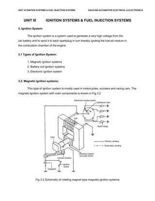
3.2. Magneto ignition systems:
This type of ignition system is mostly used in motorcycles, scooters and racing cars. The
magneto Ignition system with main components is shown in Fig.3.2
Fig 3.2 Schematic of rotating magnet type magneto ignition systems
2. UNIT -III IGNITION SYSTEMS & FUEL INJECTION SYSTEMS SAUX1004 AUTOMOTIVE ELECTRICAL & ELECTRONICS
Magneto ignition system is a special type of ignition system with its own electric
generator to provide the required necessary energy for the vehicle system. It is mounted on the
engine and replaces all components of the coil ignition system except the spark plug. A
magneto when rotated by the engine is capable of producing a very high voltage and doesn’t
need a battery as source of external energy.
The main components of an ignition coil are Distributor, Condenser, Contact Breaker
(CB) points, Ignition Coil.
There are two important types of magneto ignition system. They are 1) Rotating
armature type and 2) Rotating Magnet type.
In the first type, the armature consisting of the primary and secondary windings rotate in
between the poles of a stationary magnet. In the second type the magnet revolves and windings
are kept stationary is shown in the above figure. A third type of magneto called the polar
inductor type magneto, where both the magnet and the windings remain stationary but the
voltage is generated by reversing the flux field with the help of soft iron polar projections called
inductors.
Condensor:
The function of the capacitor is to reduce arcing at the contact breaker (CB) points. Also
when the CB opens the magnetic field in the primary winding begins to collapse. When the
magnetic field is collapsing capacitor gets fully charged and then it starts discharging and helps
in building up of voltage in secondary winding.
Contact Breaker:
It is to be noted that the Contact breaker cam and distributor rotor are mounted on the
same shaft.
Distributor:
Ignition Coil:
The main advantage of the high tension magneto ignition system is the production of a
very high voltage.Because of the poor starting characteristics of the magneto system invariably
3. UNIT -III IGNITION SYSTEMS & FUEL INJECTION SYSTEMS SAUX1004 AUTOMOTIVE ELECTRICAL & ELECTRONICS
the battery ignition system is preferred to the magneto system in automobile engines. However,
in two wheelers magneto ignition system is preferred due to light weight and less maintenance.
3.3. Battery coil ignition systems:
It is used in passenger cars and light trucks. A Battery Ignition system for four cylinder
engine where the battery supplies the electrical energy. An ignition switch is used to control the
battery current for starting or stopping the engine. The ignition coil transforms the battery low
tension current to high tension current required to produce a spark by jumping in a spark plug.
The distributor delivers the spark to the proper cylinder and incorporates the mechanical
breaker, which opens and closes the primary circuit at exact times.
The various units are connected by electrical wiring. The spark plugs provide the spark
in engine cylinder.
The figure shows battery ignition system for a 4-cylinder petrol engine. It mainly consists
of a 6 or 12 volt battery, ammeter, ignition switch, auto-transformer (step up transformer),
contact breaker, capacitor, distributor rotor, distributor contact points, spark plugs, etc.
The ignition system is divided into 2-circuits namely the Primary Circuit and Secondary
Circuit.
(i) Primary Circuit : It consists of 6 or 12 V battery, ammeter, ignition switch, primary winding it
has 200-300 turns of 20 SWG (Sharps Wire Gauge) gauge wire, contact breaker, capacitor. 53
(ii) Secondary Circuit: It consists of secondary winding. Secondary Ignition Systems winding
consists of about 21000 turns of 40 (S WG) gauge wire. Bottom end of which is connected to
bottom end of primary and top end of secondary winding is connected to centre of distributor
rotor. Distributor rotors rotate and make contacts with contact points and are connected to spark
plugs which are fitted in cylinder heads.
Working:
When the ignition switch is closed and engine in cranked, as soon as the contact
breaker closes, a low voltage current will flow through the primary winding. When the contact
breaker opens the contact, the magnetic field begins to collapse. Because of this collapsing
magnetic field, current will be induced in the secondary winding. And because of more turns of
secondary, the voltage goes upto 20000-35000 volts.
4. UNIT -III IGNITION SYSTEMS & FUEL INJECTION SYSTEMS SAUX1004 AUTOMOTIVE ELECTRICAL & ELECTRONICS
This high voltage current is brought to centre of the distributor rotor. Distributor rotor
rotates and supplies this high voltage current to proper stark plug depending upon the engine
firing order. When the high voltage current jumps the spark plug gap, it produces the spark and
the charge is ignited-combustion starts-products of combustion expand and produce power.
When compared to the magneto ignition system, the battery ignition system is more
expensive but at the same time it is very highly reliable as it aids in reliable sparking..
Fig 3.3 Schematic of battery ignition systems
3.4. Electronic ignition system:
The requirement for higher mileage, reduced emissions and greater reliability has paved
the way for development of the electronic ignition systems.
Fig 3.4 Schematic of electronic ignition systems
3.5 Relative merits
The main advantages of the electronic ignition system are
5. UNIT -III IGNITION SYSTEMS & FUEL INJECTION SYSTEMS SAUX1004 AUTOMOTIVE ELECTRICAL & ELECTRONICS
It provides better emission control.
It provides a reasonable fuel economy.
It provides better engine performance.
3.6 Distributorless Ignition System:
3.7 Centrifugal advance mechanisms:
Centrifugal advance makes the ignition coil and spark plugs fire sooner as engine speed
increases, using spring-loaded weights, centrifugal force, and lever action to rotate the
distributor cam. Spark timing is advanced by rotating the distributor cam against distributor shaft
rotation. This action helps correct ignition timing for maximum engine power. Basically the
centrifugal advance mechanism consists of two advance weights, two springs, and a advance
lever.
Fig 3.7 Centrifugal advance mechanisms
During periods of low engine speed, the springs hold the advance weights inward
towards the distributor cam or trigger wheel. At this time there is not enough centrifugal force to
push the weights outward. Timing stays at its normal initial setting.
As speed increases, centrifugal force on the weights moves them outwards against
spring tension. This movement causes the distributor cam or trigger wheel to move ahead. With
this design, the higher the engine speed, the faster the distributor shaft turns, the farther out the
advance weights move, and the farther ahead the cam is moved forward or advanced. At a
preset engine speed, the lever strikes a stop and centrifugal advance reaches maximum.
6. UNIT -III IGNITION SYSTEMS & FUEL INJECTION SYSTEMS SAUX1004 AUTOMOTIVE ELECTRICAL & ELECTRONICS
The action of the centrifugal advance causes the contact points to open sooner, or the
trigger wheel and pickup coil turn off the ECU sooner. This causes the ignition coil to
fire with the engine pistons not as far up in the cylinders.
3.8 Vacuum Advance mechanisms:
The vacuum advance provides additional spark advance when engine load is low at part
throttle position. It is a method of matching ignition timing with engine load. The vacuum
advance increases fuel economy because it helps maintain idle fuel spark advance at all times.
A vacuum advance consists of a vacuum diaphragm, link, movable distributor plate, and
a vacuum supply hose. At idle, the vacuum port from the carburetor or throttle body to the
distributor advance is covered, thereby NO vacuum is applied to the vacuum diaphragm, and
spark timing is NOT advanced. At part throttle, the throttle valve uncovers the vacuum port and
the port is exposed to engine vacuum. The vacuum pulls the diaphragm outward against spring
force. The diaphragm is linked to a movable distributor plate, which is rotated against distributor
shaft rotation and spark timing is advanced.
Fig 3.8 Vacuum advance mechanism
The vacuum advance does not produce any advance at full throttle. When the throttle
7. UNIT -III IGNITION SYSTEMS & FUEL INJECTION SYSTEMS SAUX1004 AUTOMOTIVE ELECTRICAL & ELECTRONICS
valve is wide open, vacuum is almost zero. Thus vacuum is not applied to the
distributor diaphragm and the vacuum advance does not operate.
3.9 Spark plug:
The spark plug consists of a porcelain insulator in which there is an insulated electrode
supported by a metal shell with a grounded electrode. They have a simple purpose of
supplying a fixed gap in the cylinder across which the high voltage surges from the
coil must jump after passing through the distributor.
The spark plugs use ignition coil high voltage to ignite the fuel mixture. Somewhere
between 4,000 and 10,000 volts are required to make current jump the gap at the plug
electrodes. This is much lower than the output potential of the coil.
Spark plug gap is the distance between the center and side electrodes. Normal gap
specifications range between .030 to .060 inch. Smaller spark plugs gaps are used on
older vehicles equipped with contact point ignition systems.
Spark plugs are either resistor or non-resistor types (fig. 2-46). A resistor spark plug
has internal resistance (approximately 10,000 ohms) designed to reduce the static in
radios. Most new vehicles require resistortype plugs. Non-resistor spark plug has a
solid metal rod forming the center electrode. This type of spark plugs is NOT
commonly used except for racing and off-road vehicles.
8. UNIT -III IGNITION SYSTEMS & FUEL INJECTION SYSTEMS SAUX1004 AUTOMOTIVE ELECTRICAL & ELECTRONICS
3.10 Spark Plug Heat Range and Reach
The heat range of the spark plug determines how hot the plug will get. The length and
diameter of the insulator tip and the ability of the spark plug to transfer heat into the
cooling system determine spark plug heat range.
A hot spark plug has a long insulator tip that prevents heat transfer into the
waterjackets. It will also bum off any oil deposits. This provides a self-cleaning action.
AUTOMOTIVE ELECTRICAL CIRCUITS AND WIRING 58/ 101
A cold spark plug has a shorter insulator tip and operates at a cooler temperature. The
cooler tip helps prevent overheating and preignition. A cold spark plug is used in
engines operated at high speeds.
Vehicle manufacturers recommend a specific spark plug heat range for their engines.
The heat range is coded and given as a number on the spark plug insulator. The larger
the number on the plug, the hotter the spark plug tip will operate. For example, a 54
plug would be hotter than a 44 or 34 plug.
The only time you should change from spark plug heat range specifications is when
abnormal engine or operating conditions are encountered. For instance, if the plug runs
9. UNIT -III IGNITION SYSTEMS & FUEL INJECTION SYSTEMS SAUX1004 AUTOMOTIVE ELECTRICAL & ELECTRONICS
too cool, sooty carbon will deposit on the insulator around the center electrode. This
deposit could soon build up enough to short out the plug. Then high voltage surges
would leak across the carbon instead of producing a spark across the spark plug gap.
Using a hotter plug will bum this carbon deposit away or prevent it from forming.
Spark plug reach is the distance between the end of the spark plug threads and the seat
or sealing surface of the plug. Plug reach determines how far the plug reaches through
the cylinder head. If spark plug reach is too long, the spark plug will protrude too far
into the combustion chamber and the piston at TDC may strike the electrode.
However, if the reach is too short, the plug electrode may not extend far enough into
the cylinder head and combustion efficiency will be reduced. A spark plug must reach
into the combustion chamber far enough so that the spark gap will be properly
positioned in the combustion chamber without interfering with the turbulence of the
air-fuel mixture or reducing combustion action.
Figure 2-46.- Sectional view of a (A) non-resistor and (B) resistor spark plug.
3.11 Construction of Spark Plug:
3.12 Types of spark plugs:
10. UNIT -III IGNITION SYSTEMS & FUEL INJECTION SYSTEMS SAUX1004 AUTOMOTIVE ELECTRICAL & ELECTRONICS
Introduction to feed back carburetor systems:
Carburetor is a device used for providing proper air/fuel mixture ratio. The carburetor
works on Bernoulli's principle i.e. The faster the air moves, the lower is its static pressure, and
the higher is its dynamic pressure. The throttle or accelerator linkage indirectly controls the flow
of fuel by actuating the carburetor mechanisms which meters the flow of air being pulled into the
engine. The speed of this flow, and therefore its pressure, determines the amount of fuel drawn
into the airstream.
The latest type of carburetor system is the electronic feedback design, which provides
better combustion by improved control of the air/fuel mixture. A three-way converter not only
oxidizes HC and CO but also chemically reduces oxides of nitrogen (NOX).If the air/fuel mixture
is too lean, NOX is not converted efficiently. If the mixture is too rich, HC and CO does not
oxidize efficiently. Monitoring the air/fuel ratio is the job of the exhaust gas oxygen sensor.
An oxygen sensor senses the amount of oxygen present in the exhaust stream. A lean
mixture produces a high level of oxygen in the exhaust. The oxygen sensor, placed in the
exhaust before the catalytic converter, produces a voltage signal that varies with the amount of
oxygen the sensor detects in the exhaust. If the oxygen level is high (a lean mixture), the
voltage output is low. If the oxygen level is low (a rich mixture), the voltage output is high.The
electrical output of the oxygen sensor is monitored by an electronic control unit (ECU). This
microprocessor is programmed to interpret the input signals from the sensor and in turn
generate output signals to a mixture control device that meters more or less fuel into the air
charge as it is needed to maintain the 14.7 to 1 ratio.
Whenever these components are working to control the air/fuel ratio, the carburetor is
said to be operating in closed loop. The oxygen sensor is constantly monitoring the oxygen in
the exhaust, and the control module is constantly making adjustments to the air/fuel mixture
based on the fluctuations in the sensor's voltage output. However, there are certain conditions
11. UNIT -III IGNITION SYSTEMS & FUEL INJECTION SYSTEMS SAUX1004 AUTOMOTIVE ELECTRICAL & ELECTRONICS
under which the control module ignores the signals from the oxygen sensor and does not
regulate the ratio of fuel to air. During these times, the carburetor is functioning in conventional
manner and is said to be operating in open loop. (The control cycle has been broken.)
The carburetor operates in open loop until the oxygen sensor reaches a certain
temperature (approximately 600F). The carburetor also goes into open loop when a richer-than-
normal air/fuel mixture is required, such as during warm-up and heavy throttle application.
Several other sensors are needed to alert the electronic sensor provides input relating to engine
temperature. A vacuum sensor and a throttle position sensor indicate wide open throttle.
Early feedback systems used a vacuum switch to control metering devices on the
carburetor. Closed loop signals from the electronic control module are sent to a vacuum
solenoid regulator, which in turn controls vacuum to a piston and diaphragm assembly in the
carburetor. The vacuum diaphragm and a spring above the diaphragm work together to lift and
lower a tapered fuel metering rod that moves in and out of an auxiliary fuel jet in the bottom of
the fuel bowl. The position of the metering rod in the jet controls the amount of fuel allowed to
flow into the main fuel well.
A less common method to control the air/fuel mixture is with a back suction system
feedback. The back suction system consists of an electric stepper motor, a metering pintle
valve, an internal vent restrictor, and a metering orifice. The stepper motor regulates the pintle
movement in the metering orifice, thereby varying the area of the opening communicating
control vacuum to the fuel bowl. The larger this area, the leaner the air/fuel mixture. Some of the
control vacuum is bled off through the internal vent restrictor. The internal vent restrictor also
serves to vent the fuel bowl when the back suction control pintle is in the closed position.
Throttle Body Injection(TBI):
TBI fuel injection system is a type of system where the fuel is injected into the throttle
body. The throttle body fuel injection system operates by using a single or pair of injectors. The
throttle looks like a carburetor without the fuel bowl, the metering jets or the float.
This type of fuel injection system consists of only two major castings the fuel body and the
throttle body. The fuel body supplies the fuel while the throttle body has a valve that controls the
12. UNIT -III IGNITION SYSTEMS & FUEL INJECTION SYSTEMS SAUX1004 AUTOMOTIVE ELECTRICAL & ELECTRONICS
flow of air. On the throttle, there are ports that gather signals to relay to the manifold absolute
pressure sensor and to the emission control system.
TBI Fuel Injection Advantages:
It is less expensive than using other types of fuel injection systems.
It is easier to clean, maintain and service because there are fewer parts.
It is cheaper to manufacture than a port injection system and simpler to diagnose.
It also does not have the same level of injector balance problems that a port injection system
might have when the injectors are clogged.
It greatly improves the fuel metering compared to a carburetor.
TBI Fuel Injection Disadvantages:
It is almost the same as a TBI carburetor wherein the fuel is not equally distributed
to all the cylinders. This means that the air/fuel mixture injected differs for each
cylinder.
It can cool the manifold much faster causing the fuel to puddle and condense in
the manifold. The possibility of condensation is much higher since the fuel travels
longer from the throttle body to the combustion chamber.
Since the system needs to be mounted on top of the combustion chamber, you're
prevented from modifying the manifold design to improve your car's performance.
It is a wet system and the mixture of fuel is still based per cylinder.
Ref: http://www.carsdirect.com/carmaintenance/
tbifuelinjectionthrottlebodyfuelinjectionsystems10advantagesanddisadvantages
Multi port or point fuel injection,
Fuel injection systems,
13. UNIT -III IGNITION SYSTEMS & FUEL INJECTION SYSTEMS SAUX1004 AUTOMOTIVE ELECTRICAL & ELECTRONICS
Injection system controls.
Advantages of electronic ignition systems:
Types of solid-state ignition systems and their principle of operation,
Contact less electronic ignition system,
Electronic spark timing control:
It is a closed-loop type electronic control device that continuously corrects the ignition
timing and in effect it re-tunes the engine some few times every second. By providing the
correct spark timing all the time, the fuel consumption is reduced considerably.
Setting of Ignition System
Disconnect the drive to the contact breaker cover.
Loosen the clamp of CB casing and distributor unit.
Set the piston of cylinder NO.2 on TDC against a fixed mark on engine casing.
Secure the CB camshaft in this position. The ignition timing will be set.
Firing Order Setting
Rotate the crankshaft in correct direction.
Note the order in which inlet valves(or exhaust valve) open.
This the firing order of the engine
Gap Adjustment of Contact Breaker
Turn the engine shaft manually until the contacts are freely open.
Move the fixed contact plate with the help of adjustor screw till required gap is achived
If gap is not correct, loosen the screws of fixed contact plate.
Tighten the screw of distributor securing clamp.
References:
1.http://www.seminarsonly.com/mech%20&%20auto/electronicfuelinjectionseminarreportppt.Ph
p – for electronic injection