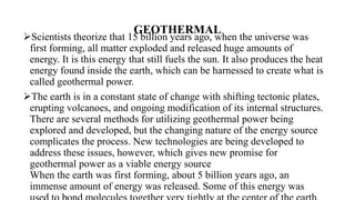
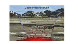
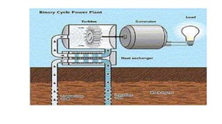
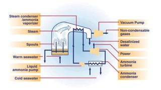
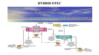
The document discusses geothermal and ocean energy, emphasizing how geothermal energy originates from the Earth's heat and can be harnessed for sustainable power through various methods like geothermal heat pumps and different types of power plants. It also covers ocean thermal energy conversion (OTEC), a process that generates electricity by exploiting the temperature difference between deep cold ocean water and warm surface water, highlighting its potential benefits for energy and freshwater production. Overall, both energy sources are highlighted as clean, renewable options for reducing air pollution and providing reliable energy.

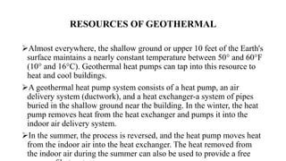


![[PPT] on Steam Turbine](https://cdn.slidesharecdn.com/ss_thumbnails/spsharmafinalppt-140608082156-phpapp01-thumbnail.jpg?width=640&height=640&fit=bounds)


![Gas turbine-power-plant[1]](https://cdn.slidesharecdn.com/ss_thumbnails/gas-turbine-power-plant1-150515182411-lva1-app6892-thumbnail.jpg?width=640&height=640&fit=bounds)


