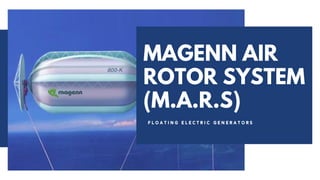
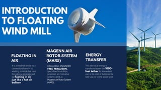
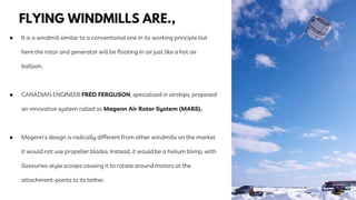
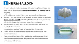
The document summarizes a technical seminar presentation on floating electric generators called Magenn Air Rotor Systems (MARS). MARS are wind turbines that float in the air tethered to the ground by wires, allowing them to access stronger winds at higher altitudes than traditional windmills. They work similarly to conventional wind turbines by using wind to spin rotors and generators to produce electricity, but remain aloft using helium balloons. Prototypes have generated up to 2 kW of power, enough for one home. Advantages include access to stronger winds, but challenges include high costs and safety in bad weather.


![While in the sky, the MARS
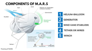
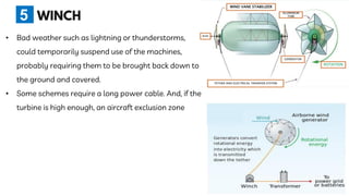
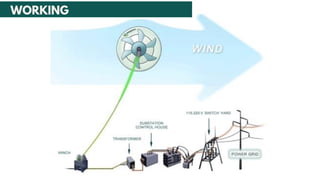
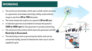
• The wind turbine generator converts mechanical
energy to electrical energy.
• Turbine spins in the wind, generating electricity.
The current is transferred down the tether for
consumption, battery storage or transmitted to
a power grid
• Over speed controls are built into the design of
MARS.
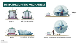
• The MARS units will have an internal bladder
system to maintain pressure.
2
[1 kW = 1.340 horsepower]](https://image.slidesharecdn.com/1-210601114134/85/MAGENN-AIR-ROTOR-SYSTEM-M-A-R-S-ppt-19-320.jpg)


![YATHISH TECHNICAL SEM PPT [Autosaved].pptx](https://cdn.slidesharecdn.com/ss_thumbnails/yathishtechnicalsempptautosaved-240425115828-a4e1b85d-thumbnail.jpg?width=640&height=640&fit=bounds)


