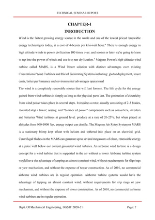
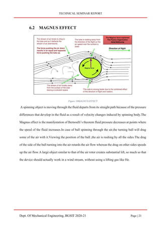
The document describes the Magenn Air Rotor System (MARS), which is a floating electric generator that uses wind power. MARS consists of a helium-filled balloon tethered to the ground that rotates in the wind to generate electricity. It has several components, including the helium balloon, tethers, generator, blades, and cooling system. MARS is designed to take advantage of stronger winds at higher altitudes compared to traditional wind turbines. The electricity generated is transferred to the ground via the tether and can be used or stored immediately.

![TECHNICAL SEMINAR REPORT
Dept. Of Mechanical Engineering, BGSIT 2020-21 Page | 25
CHAPTER-8
POWER GENERATION
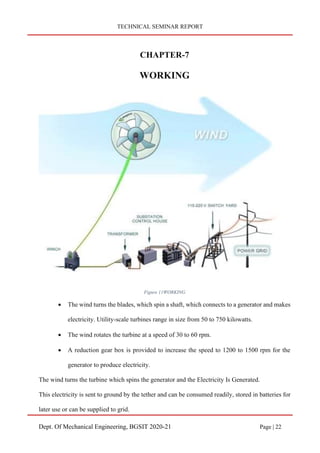
The wind pushes the rotor blades, converting kinetic energy to rotary motion. This spins a low-
speed shaft, which turns a gear at the lower end. The gear in turn drives a smaller gear on a high-
speed shaft that runs through generator housing.
A magnetic rotor on the high-speed shaft spins inside loops of copper wire that are wound around
an iron core. This creates "electromagnetic induction" through the coils and generates an electric
current. The current must be regulated for the strength of current desired (110 w in the US for
household AC current). It is then fed into a grid or routed into a battery bank for later use.
In the presence of high winds, floating rotor is capable of exerting a traction force equivalent to
several hundred kilo Newtons, moving at speeds that can exceed 80 m/s. The product of the force
multiplied by the speed provides to the order of magnitude of the potential power generated by the
kite:
P = F. V
A single balloon has the theoretical potential at a speed of 80 m/s and a force of 100,000 Newtons
of generating a power of:
P ≈ 100x103.80
≈ 8x10⁶[Watt]
= 8[MW]
which exceeds the rated power of existing horizontal axis wind turbines at 7 MW.
The floating wind generator can be envisioned as a giant carousel, solidly anchored to the ground.
Its nucleus consists of a central structure, tall enough to support the arms by means of a tenso
structure. This carousel is put into motion by the wind itself that drag the wind rotor out from their](https://image.slidesharecdn.com/2-210601114135/85/MAGENN-AIR-ROTOR-SYSTEM-M-A-R-S-Report-25-320.jpg)


![YATHISH TECHNICAL SEM PPT [Autosaved].pptx](https://cdn.slidesharecdn.com/ss_thumbnails/yathishtechnicalsempptautosaved-240425115828-a4e1b85d-thumbnail.jpg?width=640&height=640&fit=bounds)


