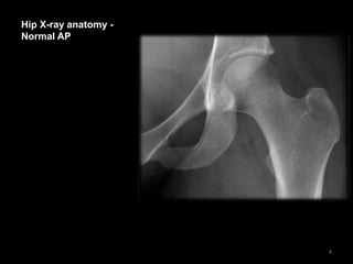
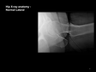
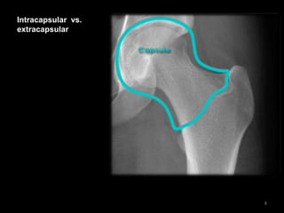
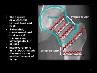
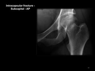
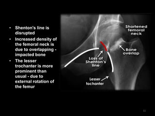
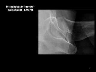
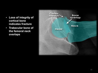
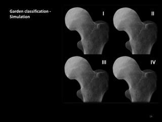
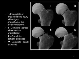
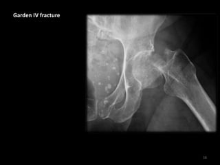
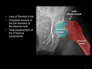
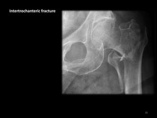
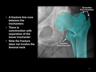
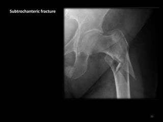
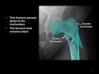
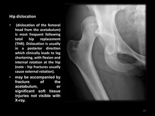
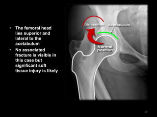
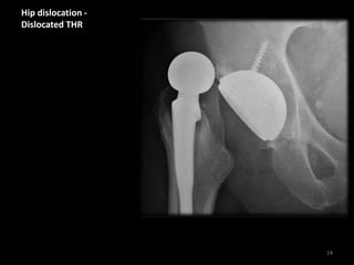
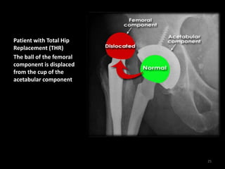
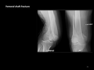
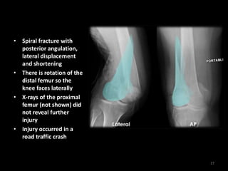
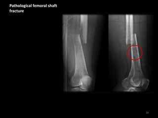
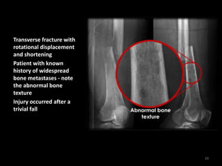
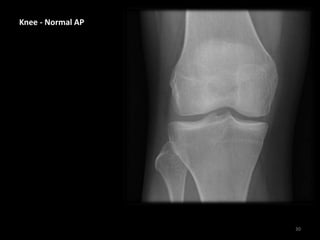
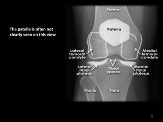
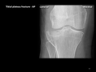
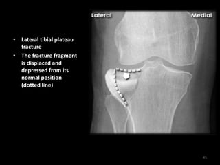
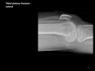
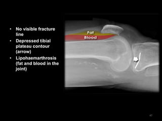
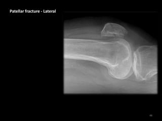
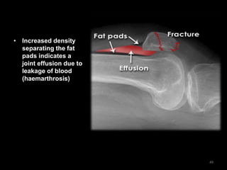
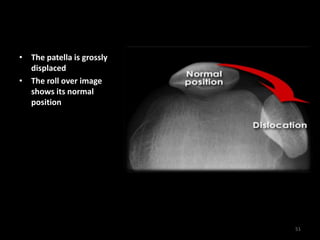
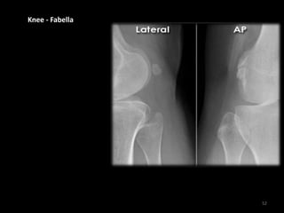
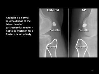
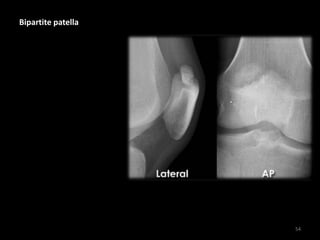
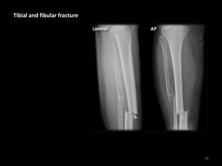
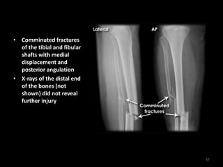
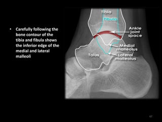
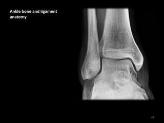
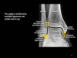
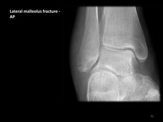
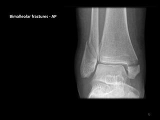
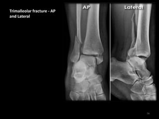
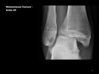
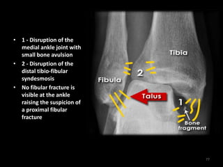
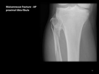
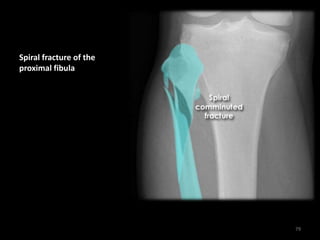
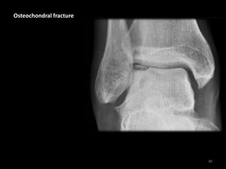
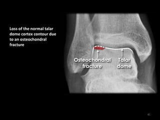
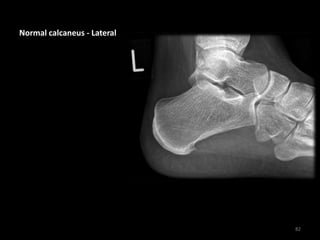
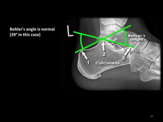
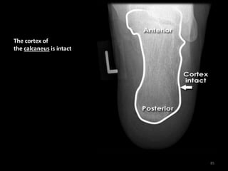
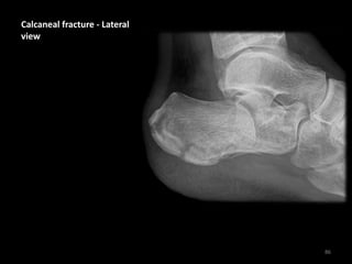
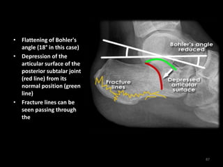
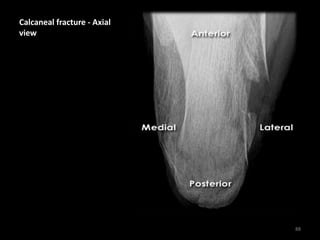
Lower limb fractures
X-Rays
Abbas A. A. Shawka
Right v left example -
Pelvis and hips
Right v left example -
Pelvis and hips
• This image of the pelvis
shows subtle
irregularity of the
cortical outline of the
right femoral neck
• Comparison with the
other side - which is
asymptomatic -
increases confidence of
a genuine abnormality
• There is also loss of the
normal trabecular
pattern indicating a
fracture (#) 2
Clinical information
•Right groin pain after
a fall
•Shortened and
externally rotated right
leg
Diagnosis
•Fractured neck of
right femur
3
Hip X-ray anatomy -
Normal AP
4
• Shenton's line is
formed by the
medial edge of the
femoral neck and
the inferior edge of
the superior pubic
ramus
• Loss of contour of
Shenton's line is a
sign of a fractured
neck of femur
• IMPORTANT NOTE:
Fractures of the
femoral neck do not
always cause loss
of Shenton's line
5
Hip X-ray anatomy -
Normal Lateral
6
• The cortex of the
proximal femur is
intact
• The Lateral view is
often not so clear
because those with
hip pain find the
positioning required
difficult
7
Intracapsular vs.
extracapsular
8
• The capsule
envelopes the
femoral head and
neck
• Subcapital,
transcervical and
basicervical
fractures are
intracapsular hip
injuries
• Intertrochanteric
and subtrochanteric
fractures do not
involve the neck of
femur
9
Intracapsular fracture -
Subcapital - AP
10
• Shenton's line is
disrupted
• Increased density of
the femoral neck is
due to overlapping -
impacted bone
• The lesser
trochanter is more
prominent than
usual - due to
external rotation of
the femur
11
Intracapsular fracture -
Subcapital - Lateral
12
• Loss of integrity of
cortical bone
indicates fracture
• Trabecular bone of
the femoral neck
overlaps
13
Garden classification -
Simulation
14
`
• I - Incomplete or
impacted bone injury
with valgus
angulation of the
distal component
• II - Complete (across
whole neck) -
undisplaced
• III - Complete -
partially displaced
• IV - Complete - totally
displaced
15
Garden IV fracture
16
• Loss of Shenton's line
• Complete fracture of
the full diameter of
the femoral neck
• Total displacement of
the 2 fracture
components
17
Intertrochanteric fracture
18
• A fracture line runs
between the
trochanters
• There is
comminution with
separation of the
lesser trochanter
• Note the fracture
does not involve the
femoral neck
19
Subtrochanteric fracture
20
• This fracture passes
distal to the
trochanters
• The femoral neck
remains intact
21
Hip dislocation
• (dislocation of the femoral
head from the acetabulum)
is most frequent following
total hip replacement
(THR). Dislocation is usually
in a posterior direction
which clinically leads to leg
shortening, with flexion and
internal rotation at the hip
(note - hip fractures usually
cause external rotation).
• may be accompanied by
fracture of the
acetabulum, or
significant soft tissue
injuries not visible with
X-ray.
22
• The femoral head
lies superior and
lateral to the
acetabulum
• No associated
fracture is visible in
this case but
significant soft
tissue injury is likely
23
Hip dislocation -
Dislocated THR
24
Patient with Total Hip
Replacement (THR)
The ball of the femoral
component is displaced
from the cup of the
acetabular component
25
Femoral shaft fracture
26
• Spiral fracture with
posterior angulation,
lateral displacement
and shortening
• There is rotation of the
distal femur so the
knee faces laterally
• X-rays of the proximal
femur (not shown) did
not reveal further
injury
• Injury occurred in a
road traffic crash
27
Pathological femoral shaft
fracture
28
Transverse fracture with
rotational displacement
and shortening
Patient with known
history of widespread
bone metastases - note
the abnormal bone
texture
Injury occurred after a
trivial fall
29
Knee - Normal AP
30
The patella is often not
clearly seen on this view
31
Knee – Normal AP
32
• This x-ray showing the
cartilage ( hyaline ) ,
meniscus and joint soft
tissue.
• We can not specific any
abnormality for knee
components unless we
request MRI for the
patient.
33
MRI – Knee – Normal
34
MRI for the Knee joint is
used to determine the
defects in meniscus,
cartilage , cruciate
ligaments and other
ligaments.
35
MRI – Knee – Normal
36
37
MRI – Knee – Normal
38
39
Knee - Normal Lateral
(Horizontal Beam)
40
• The Horizontal Beam
Lateral view is useful
for assessing soft
tissues as well as bones
• The quadriceps and
patellar tendons are
visible
• Note the normal
suprapatellar pouch
between fat pads
above the patella
(asterisks) - widening
of these fat pads or
increased density in
this area can indicate a
knee joint effusion
41
Knee - Normal 'Skyline'
view
42
• Not usually indicated in
the context of trauma
• More helpful to assess
knee pain due to
suspected
patellofemoral
compartment
osteoarthritis
• Normal patellofemoral
compartment spacing
(arrowheads)
43
Tibial plateau fracture - AP
44
• Lateral tibial plateau
fracture
• The fracture fragment
is displaced and
depressed from its
normal position
(dotted line)
45
Tibial plateau fracture -
Lateral
46
• No visible fracture
line
• Depressed tibial
plateau contour
(arrow)
• Lipohaemarthrosis
(fat and blood in the
joint)
47
Patellar fracture - Lateral
48
• Increased density
separating the fat
pads indicates a
joint effusion due to
leakage of blood
(haemarthrosis)
49
Patellar dislocation - Skyline
view
50
• The patella is grossly
displaced
• The roll over image
shows its normal
position
51
Knee - Fabella
52
A fabella is a normal
sesamoid bone of the
lateral head of
gastrocnemius tendon -
not to be mistaken for a
fracture or loose body
53
Bipartite patella
54
• The patella is bipartite
(in 2 parts) - a common
normal variant
• Note: Injury to the
interface of the 2
components is possible
which may be
symptomati
55
Tibial and fibular fracture
56
• Comminuted fractures
of the tibial and fibular
shafts with medial
displacement and
posterior angulation
• X-rays of the distal end
of the bones (not
shown) did not reveal
further injury
57
Tibial stress fracture
58
• Periosteal stress
reaction are signs of
stress injury (often not
present on the initial X-
ray)
• History of chronic pain
worsened by activity
59
Toddler's fracture
60
• Fine spiral line through
the tibial shaft
• This toddler presented
with refusal to weight-
bear
61
Toddler's fracture
62
• Fine spiral line through
the tibial shaft
• This toddler presented
with refusal to weight-
bear
63
Ankle anatomy - Normal
AP 'mortise'
64
• The weight-bearing
portion is formed by
the tibial plafond and
the talar dome
• The joint extends into
the 'lateral gutter' (1)
and the 'medial gutter'
(2)
• The joint is evenly
spaced throughout
65
Ankle anatomy - Normal
Lateral
66
• Carefully following the
bone contour of the
tibia and fibula shows
the inferior edge of the
medial and lateral
malleoli
67
Ankle bone and ligament
anatomy
68
The ankle is stabilised by
multiple ligaments not
visible with X-ray
69
Lateral malleolus fracture -
AP
70
• Soft tissue swelling
laterally (asterisks)
• Transverse fracture of
fibular tip (Weber A)
• The ankle joint remains
aligned normally
• Weber A = Distal
to ankle joint (this case)
• Weber B = At level
of ankle joint
• Weber C = Proximal
to ankle joint
71
Bimalleolar fractures - AP
72
• Transverse medial
malleolus fracture
• Lateral malleolus
fracture - at level
of ankle joint (WeberB)
• Joint widened medially
due to lateral
displacement of the
talus
73
Trimalleolar fracture - AP
and Lateral
74
1 - Medial malleolus fracture
2 - Lateral malleolus fracture -
proximal to the ankle and
extending up the fibula (Weber
C fracture)
3 - Posterior malleolus fracture
• The joint is unstable and
widened anteriorly
(arrowheads) and at the
distal tibiofibular
syndesmosis (asterisk)
• The talus is displaced
posteriorly and laterally
along with the medial and
lateral malleolus bone
fragments
75
Maisonneuve fracture -
Ankle AP
76
• 1 - Disruption of the
medial ankle joint with
small bone avulsion
• 2 - Disruption of the
distal tibio-fibular
syndesmosis
• No fibular fracture is
visible at the ankle
raising the suspicion of
a proximal fibular
fracture
77
Maisonneuve fracture - AP
proximal tibia-fibula
78
Spiral fracture of the
proximal fibula
79
Osteochondral fracture
80
Loss of the normal talar
dome cortex contour due
to an osteochondral
fracture
81
Normal calcaneus - Lateral
82
Bohler's angle is normal
(39° in this case)
83
Normal calcaneus - Axial
84
The cortex of
the calcaneus is intact
85
Calcaneal fracture - Lateral
view
86
• Flattening of Bohler's
angle (18° in this case)
• Depression of the
articular surface of the
posterior subtalar joint
(red line) from its
normal position (green
line)
• Fracture lines can be
seen passing through
the calcaneus
87
Calcaneal fracture - Axial
view
88
Loss of smooth cortical
edge (orange line)
89
Foot X-ray anatomy - DP
and Oblique views
90
• Hindfoot = Calcaneus +
Talus
• Midfoot = Navicular +
Cuboid + Cuneiforms
• Forefoot = Metatarsals
+ Phalanges
• 1 = Hind-midfoot
junction
• 2 = Mid-forefoot
junction =
Tarsometatarsal joints
(TMTJs)
91
Foot X-ray anatomy - DP
and Oblique views
92
Metatarsals and phalanges
of the toes are numbered 1
to 5
1 = Big toe
5 = Little toe
MC = Medial Cuneiform
IC = Intermediate
Cuneiform
LC = Lateral Cuneiform
93
Forefoot X-ray anatomy -
Joints
94
MTPJ = Metatarsophalangeal
Joints
IPJ = Interphalangeal Joint
(of big toe only)
PIPJ = Proximal
Interphalangeal Joints
DIPJ = Distal Interphalangeal
Joints
Note the medial side
sesamoid is 'bipartite' (in 2
parts) - this is a common
normal variant - not a
fracture
95
Foot ligament anatomy
96
• DP - Normal alignment
of the 2nd Metatarsal
with the Intermediate
Cuneiform
• Oblique - Normal
alignment of the 3rd
Metatarsal with the
Lateral Cuneiform
• Position of the Lisfranc
Ligament shown
97
Lisfranc injury - DP
98
• Second metatarsal
displaced from the
intermediate
cuneiform
• No fracture is visible
but this is a severe
injury which is
debilitating if
untreated
• Note: Lisfranc ligament
injury can be subtle
and does not always
result in displacement -
If there is a clinically
suspected ligament
injury then clinical and
radiological follow-up
must be arranged
99
Metatarsal shaft fracture
100
• Oblique fracture of the
5th Metatarsal shaft
• Fracture more clearly
visible on the oblique
image
101
5th metatarsal base
fracture
102
• Left image - The
fracture line passes
transversely across the
bone
• Right image - A normal
unfused 5th metatarsal
base apophysis is
aligned more
longitudinally along
the bone
103
Metatarsal stress fracture
104
• Subtle periosteal stress
reaction of the 2nd
metatarsal
• History of chronic pain
worsened by activity
• Note: Stress fractures
are not always visible
on the initial X-ray - if
suspected repeat X-ray
or MRI may be
required
105
Thank you
106

lowerlimbfractures-170325175714.pdf

  • 1.
  • 2.
    Right v leftexample - Pelvis and hips Right v left example - Pelvis and hips • This image of the pelvis shows subtle irregularity of the cortical outline of the right femoral neck • Comparison with the other side - which is asymptomatic - increases confidence of a genuine abnormality • There is also loss of the normal trabecular pattern indicating a fracture (#) 2
  • 3.
    Clinical information •Right groinpain after a fall •Shortened and externally rotated right leg Diagnosis •Fractured neck of right femur 3
  • 4.
    Hip X-ray anatomy- Normal AP 4
  • 5.
    • Shenton's lineis formed by the medial edge of the femoral neck and the inferior edge of the superior pubic ramus • Loss of contour of Shenton's line is a sign of a fractured neck of femur • IMPORTANT NOTE: Fractures of the femoral neck do not always cause loss of Shenton's line 5
  • 6.
    Hip X-ray anatomy- Normal Lateral 6
  • 7.
    • The cortexof the proximal femur is intact • The Lateral view is often not so clear because those with hip pain find the positioning required difficult 7
  • 8.
  • 9.
    • The capsule envelopesthe femoral head and neck • Subcapital, transcervical and basicervical fractures are intracapsular hip injuries • Intertrochanteric and subtrochanteric fractures do not involve the neck of femur 9
  • 10.
  • 11.
    • Shenton's lineis disrupted • Increased density of the femoral neck is due to overlapping - impacted bone • The lesser trochanter is more prominent than usual - due to external rotation of the femur 11
  • 12.
  • 13.
    • Loss ofintegrity of cortical bone indicates fracture • Trabecular bone of the femoral neck overlaps 13
  • 14.
  • 15.
    ` • I -Incomplete or impacted bone injury with valgus angulation of the distal component • II - Complete (across whole neck) - undisplaced • III - Complete - partially displaced • IV - Complete - totally displaced 15
  • 16.
  • 17.
    • Loss ofShenton's line • Complete fracture of the full diameter of the femoral neck • Total displacement of the 2 fracture components 17
  • 18.
  • 19.
    • A fractureline runs between the trochanters • There is comminution with separation of the lesser trochanter • Note the fracture does not involve the femoral neck 19
  • 20.
  • 21.
    • This fracturepasses distal to the trochanters • The femoral neck remains intact 21
  • 22.
    Hip dislocation • (dislocationof the femoral head from the acetabulum) is most frequent following total hip replacement (THR). Dislocation is usually in a posterior direction which clinically leads to leg shortening, with flexion and internal rotation at the hip (note - hip fractures usually cause external rotation). • may be accompanied by fracture of the acetabulum, or significant soft tissue injuries not visible with X-ray. 22
  • 23.
    • The femoralhead lies superior and lateral to the acetabulum • No associated fracture is visible in this case but significant soft tissue injury is likely 23
  • 24.
  • 25.
    Patient with TotalHip Replacement (THR) The ball of the femoral component is displaced from the cup of the acetabular component 25
  • 26.
  • 27.
    • Spiral fracturewith posterior angulation, lateral displacement and shortening • There is rotation of the distal femur so the knee faces laterally • X-rays of the proximal femur (not shown) did not reveal further injury • Injury occurred in a road traffic crash 27
  • 28.
  • 29.
    Transverse fracture with rotationaldisplacement and shortening Patient with known history of widespread bone metastases - note the abnormal bone texture Injury occurred after a trivial fall 29
  • 30.
  • 31.
    The patella isoften not clearly seen on this view 31
  • 32.
  • 33.
    • This x-rayshowing the cartilage ( hyaline ) , meniscus and joint soft tissue. • We can not specific any abnormality for knee components unless we request MRI for the patient. 33
  • 34.
    MRI – Knee– Normal 34
  • 35.
    MRI for theKnee joint is used to determine the defects in meniscus, cartilage , cruciate ligaments and other ligaments. 35
  • 36.
    MRI – Knee– Normal 36
  • 37.
  • 38.
    MRI – Knee– Normal 38
  • 39.
  • 40.
    Knee - NormalLateral (Horizontal Beam) 40
  • 41.
    • The HorizontalBeam Lateral view is useful for assessing soft tissues as well as bones • The quadriceps and patellar tendons are visible • Note the normal suprapatellar pouch between fat pads above the patella (asterisks) - widening of these fat pads or increased density in this area can indicate a knee joint effusion 41
  • 42.
    Knee - Normal'Skyline' view 42
  • 43.
    • Not usuallyindicated in the context of trauma • More helpful to assess knee pain due to suspected patellofemoral compartment osteoarthritis • Normal patellofemoral compartment spacing (arrowheads) 43
  • 44.
  • 45.
    • Lateral tibialplateau fracture • The fracture fragment is displaced and depressed from its normal position (dotted line) 45
  • 46.
  • 47.
    • No visiblefracture line • Depressed tibial plateau contour (arrow) • Lipohaemarthrosis (fat and blood in the joint) 47
  • 48.
  • 49.
    • Increased density separatingthe fat pads indicates a joint effusion due to leakage of blood (haemarthrosis) 49
  • 50.
    Patellar dislocation -Skyline view 50
  • 51.
    • The patellais grossly displaced • The roll over image shows its normal position 51
  • 52.
  • 53.
    A fabella isa normal sesamoid bone of the lateral head of gastrocnemius tendon - not to be mistaken for a fracture or loose body 53
  • 54.
  • 55.
    • The patellais bipartite (in 2 parts) - a common normal variant • Note: Injury to the interface of the 2 components is possible which may be symptomati 55
  • 56.
    Tibial and fibularfracture 56
  • 57.
    • Comminuted fractures ofthe tibial and fibular shafts with medial displacement and posterior angulation • X-rays of the distal end of the bones (not shown) did not reveal further injury 57
  • 58.
  • 59.
    • Periosteal stress reactionare signs of stress injury (often not present on the initial X- ray) • History of chronic pain worsened by activity 59
  • 60.
  • 61.
    • Fine spiralline through the tibial shaft • This toddler presented with refusal to weight- bear 61
  • 62.
  • 63.
    • Fine spiralline through the tibial shaft • This toddler presented with refusal to weight- bear 63
  • 64.
    Ankle anatomy -Normal AP 'mortise' 64
  • 65.
    • The weight-bearing portionis formed by the tibial plafond and the talar dome • The joint extends into the 'lateral gutter' (1) and the 'medial gutter' (2) • The joint is evenly spaced throughout 65
  • 66.
    Ankle anatomy -Normal Lateral 66
  • 67.
    • Carefully followingthe bone contour of the tibia and fibula shows the inferior edge of the medial and lateral malleoli 67
  • 68.
    Ankle bone andligament anatomy 68
  • 69.
    The ankle isstabilised by multiple ligaments not visible with X-ray 69
  • 70.
  • 71.
    • Soft tissueswelling laterally (asterisks) • Transverse fracture of fibular tip (Weber A) • The ankle joint remains aligned normally • Weber A = Distal to ankle joint (this case) • Weber B = At level of ankle joint • Weber C = Proximal to ankle joint 71
  • 72.
  • 73.
    • Transverse medial malleolusfracture • Lateral malleolus fracture - at level of ankle joint (WeberB) • Joint widened medially due to lateral displacement of the talus 73
  • 74.
    Trimalleolar fracture -AP and Lateral 74
  • 75.
    1 - Medialmalleolus fracture 2 - Lateral malleolus fracture - proximal to the ankle and extending up the fibula (Weber C fracture) 3 - Posterior malleolus fracture • The joint is unstable and widened anteriorly (arrowheads) and at the distal tibiofibular syndesmosis (asterisk) • The talus is displaced posteriorly and laterally along with the medial and lateral malleolus bone fragments 75
  • 76.
  • 77.
    • 1 -Disruption of the medial ankle joint with small bone avulsion • 2 - Disruption of the distal tibio-fibular syndesmosis • No fibular fracture is visible at the ankle raising the suspicion of a proximal fibular fracture 77
  • 78.
    Maisonneuve fracture -AP proximal tibia-fibula 78
  • 79.
    Spiral fracture ofthe proximal fibula 79
  • 80.
  • 81.
    Loss of thenormal talar dome cortex contour due to an osteochondral fracture 81
  • 82.
  • 83.
    Bohler's angle isnormal (39° in this case) 83
  • 84.
  • 85.
    The cortex of thecalcaneus is intact 85
  • 86.
    Calcaneal fracture -Lateral view 86
  • 87.
    • Flattening ofBohler's angle (18° in this case) • Depression of the articular surface of the posterior subtalar joint (red line) from its normal position (green line) • Fracture lines can be seen passing through the calcaneus 87
  • 88.
    Calcaneal fracture -Axial view 88
  • 89.
    Loss of smoothcortical edge (orange line) 89
  • 90.
    Foot X-ray anatomy- DP and Oblique views 90
  • 91.
    • Hindfoot =Calcaneus + Talus • Midfoot = Navicular + Cuboid + Cuneiforms • Forefoot = Metatarsals + Phalanges • 1 = Hind-midfoot junction • 2 = Mid-forefoot junction = Tarsometatarsal joints (TMTJs) 91
  • 92.
    Foot X-ray anatomy- DP and Oblique views 92
  • 93.
    Metatarsals and phalanges ofthe toes are numbered 1 to 5 1 = Big toe 5 = Little toe MC = Medial Cuneiform IC = Intermediate Cuneiform LC = Lateral Cuneiform 93
  • 94.
  • 95.
    MTPJ = Metatarsophalangeal Joints IPJ= Interphalangeal Joint (of big toe only) PIPJ = Proximal Interphalangeal Joints DIPJ = Distal Interphalangeal Joints Note the medial side sesamoid is 'bipartite' (in 2 parts) - this is a common normal variant - not a fracture 95
  • 96.
  • 97.
    • DP -Normal alignment of the 2nd Metatarsal with the Intermediate Cuneiform • Oblique - Normal alignment of the 3rd Metatarsal with the Lateral Cuneiform • Position of the Lisfranc Ligament shown 97
  • 98.
  • 99.
    • Second metatarsal displacedfrom the intermediate cuneiform • No fracture is visible but this is a severe injury which is debilitating if untreated • Note: Lisfranc ligament injury can be subtle and does not always result in displacement - If there is a clinically suspected ligament injury then clinical and radiological follow-up must be arranged 99
  • 100.
  • 101.
    • Oblique fractureof the 5th Metatarsal shaft • Fracture more clearly visible on the oblique image 101
  • 102.
  • 103.
    • Left image- The fracture line passes transversely across the bone • Right image - A normal unfused 5th metatarsal base apophysis is aligned more longitudinally along the bone 103
  • 104.
  • 105.
    • Subtle periostealstress reaction of the 2nd metatarsal • History of chronic pain worsened by activity • Note: Stress fractures are not always visible on the initial X-ray - if suspected repeat X-ray or MRI may be required 105
  • 106.