This laboratory kit provides a low-cost and portable process control system for teaching automation processes. The kit consists of two water tank systems equipped with sensors, mixers, heaters and pumps that are controlled by a PLC and SCADA interface. The total materials cost less than $1000 USD, making it affordable. Performance tests showed that components like pumps, sensors and controls worked properly to simulate industrial processes. Student evaluations found the hands-on kit helped illustrate process control applications better than simulations alone.
![TELKOMNIKA, Vol.16, No.1, February 2018, pp. 232~240
ISSN: 1693-6930, accredited A by DIKTI, Decree No: 58/DIKTI/Kep/2013
DOI: 10.12928/TELKOMNIKA.v16i1.6888 232
Received November 20, 2017; Revised January 29, 2018; Accepted February 25, 2018
Low-cost and Portable Process Control Laboratory Kit
Ade Gafar Abdullah*
1
, Dadang Lukman Hakim
2
, Muhammad Afif Auliya
3
, Asep Bayu Dani
Nandiyanto
4
, Lala Septem Riza
5
1,2,3
Electrical Engineering Department, Universitas Pendidikan Indonesia, Bandung, Indonesia
4
Department Kimia, Universitas Pendidikan Indonesia, Bandung, Indonesia
5
Department of Computer Science Education, Universitas Pendidikan Indonesia, Bandung, Indonesia
*Corresponding author, e-mail: ade_gaffar@upi.edu
Abstract
The purpose of this study was to demonstrate a new design of low-cost and portable laboratory
kit that is prospective for supporting teaching and learning on the automation process. The kit consists of
the water tank filling system (sizes of 50 mL; as a model for describing reallistic tank in the plant) equipped
with a programmable logic controller (PLC) integrated with SCADA system, human machine interface
(HMI) monitor, reservoir, temperature, water level sensors, mixer, and heater. To be adaptable in any
types of classroom,the kitwas placed on the portable table (length x width x height of 100 x 50 x 150 cm).
To approach the industrial tank system in industry, the tank was designed to be mixed and connected to
other tank, and the temperature and water volumetric (water level) was controllable. To examine the
impact of the designed kit on the improvement of teaching and learning process, the problem based
learning (PBL) approach was also conducted in class. The economic analysis result showed that the
presentkit is inexpensive and portable, compared to other commercially available kits/devices. The PBL
results showed that the kitis simple and to give better illustrations for students to comprehend the process
control system in the realistic application in industry. Further developments of this kit is potentially
implemented as an experimental tool for undergraduate students.
Keywords: control system prototype, water tank filling systems, programmable logic controller, SCADA
system, problem based learning
Copyright © 2018 Universitas Ahmad Dahlan. All rights reserved.
1. Introduction
Industrial automation is one of the important subjects for electrical engineering students.
To get minimum requirement in this course, students have to understand about the process
control. To consider realistic conditions, the course must be comprehended with experimental
studies [1-2]. In the developed countries, the course is usually supported by sophisticated
teaching devices for conducting the experimental process in the ideal condition. However, in the
developing countries (such as Indonesia), this course has a limitation, making students to
memorize the concept without deep understanding on the subject. Due to the limitations of lab
tools in the laboratory, students often have difficulty in obtaining contextual experience in their
learning process [3]. Though the experience of applying practical knowledge can make it easier
for engineering students to handle their work in the future [4]. Laboratory practice is an
important activity in engineering education [5]. It's associated with their first experience in
learning, thinking and problems solving [6-7]. Limitations of learning resources and laboratory
equipment have always been the main problem cause of students not gaining practical
experience in learning [8-9]. The learning process becomes not optimal, because laboratorium
devices are inadequate. The alternative to solve this problem can be done with computer-based
simulation. The analysis and design of this control process requires software such as
Matlab [10], Labview [11], and Wonderware in Touch [12] etc., to purchase licenses
unreachable by the laboratory budget. The use of physical plants for industrial automation
learning is even more difficult to realize, because the price is very expensive. Therefore to
overcome these problems we have to develop their own equipment.
To solve the problems, several researchers have suggested the use of strategies:
interactive remote laboratory for practicing control engineering process [13], LEGO prototype for
control system laboratory [14-16], SCADA for monitoring hybrid wind-PV [17], and digital
converter design [18]. The suggested strategies are effective and can be implemented in the](https://image.slidesharecdn.com/296888-200820054622/85/Low-cost-and-Portable-Process-Control-Laboratory-Kit-1-320.jpg)
![TELKOMNIKA ISSN: 1693-6930
Low-cost and Portable Process Control Laboratory Kit (Ade Gafar Abdullah)
233
class [19-22] and user friendly for student [23]. However, several problems are still persisted.
The laboratory kits can not describe in detail about their applications to illustrate students for the
realistic condition [24]. Further, the kits are complicated and sophisticated, creating conflicts to
the limitation of experimental rooms.
Here, the purpose of this study was to demonstrate a new design of low-cost and
portable laboratory kit that is prospective for supporting teaching and learning on the automation
process. Different from other laboratory kits, our kit is categorized as an easy-to-assemble
device. Further, the kit is relatively portable with relatively small in dimension (length x width x
height of 100 x 50 x 150 cm) and adaptable for being used in various places and classrooms.
These novelty makes the kit suitable for developing countries that have many limitations in the
experimental rooms and fund. The kit consisted of water tank filling system tank with various
features, including control in temperature, water volumetric (water level), and mixing process.
Water tank filling system was used as a model in this study because of its widely used in some
industries.
2. Design and Implementation of the Process Control Laboratory Kit
2.1. Design of Process Control Laboratory Kit
Figures 1 and 2 are the layout of the devices. The apparatus consisted of two water
tank filling systems [25], which was equipped by Programme Logic Controller (PLC) [26]
integrated with Supervisory Control and Data Acquisition (SCADA) [27] system, Human
Machine Interface (HMI) monitor [28], a reservoir, two plastic tanks with a volume size of about
50 mL, temperature and water level sensors, mixer, and heater. The apparatus was set and put
on the table (141 x 106 cm) as shown in Figure 1. Table legs can be detached, making this
table flexible, easy to be carried, re-assembled, and set in various places. We also attached
shelf (for placing unused plant panel) and put wheels in every table leg (for facilitating mobility
and access when the table is carried out) as shown in Figure 2.
Figure 1. Dimension of the present process
control laboratory kit
Figure 2. Illustration of the present process
control laboratory kit
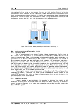
HMI monitor is used as an interface between operator and machine. The size of monitor
is 7 inch, whereas the dimension of HMI panel is 28 x 20 cm. We used a PLC with input-output
(I/O), equipped with a voltage of 220V AC, 24V DC, and 12V DC. DC voltage source can be
controlled until maximum voltage of 21V. To connect HMI and PLC, we used connector RS-232
type. Transfer USB cable from HMI to the computer was also attached, which was used for
collecting experimental data.
Figure 3 shows an illustration image of the process control laboratory kit. We used two
types of tanks, in which these tanks were filled with water during the experiment. Every tank](https://image.slidesharecdn.com/296888-200820054622/85/Low-cost-and-Portable-Process-Control-Laboratory-Kit-2-320.jpg)
![TELKOMNIKA ISSN: 1693-6930
Low-cost and Portable Process Control Laboratory Kit (Ade Gafar Abdullah)
235
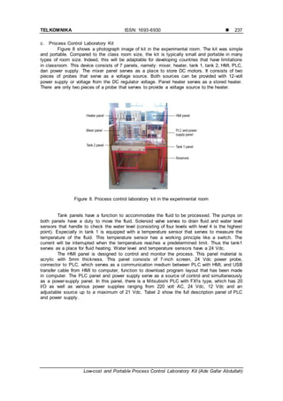
Figure 4. I/O wiring diagram
2.2.3. Human Machine Interface
Figures 5 and 6 are HMI results for automatic and manual modes, respectively. The
experimental results from the process can be observed in the computer monitor. The design of
HMI was equipped by controlling buttons for start, stop, and reset. The HMI was also equipped
by an indicator lamp to show whether the process was conducted or not.
Figure 5. Photograph image of HMI auto
mode
Figure 6. Photograph image of HMI manual
mode
2.2.3. Application of Control System for Undergraduate Students
To confirm the effectiveness of the process control laboratory kit, we tested this kit to 40
students of Electrical Engineering Education Department in Universitas Pendidikan Indonesia.
The test was conducted in the process control course, including eight theoretical and eight
experimental class sessions. In the theoretical class session, the class was started with
introduction of industrial otomation, plant system, control system and PLC, design of control
system, field bus, SCADA, industrial communication protocol, ability analysis, and safety
analysis. In this session, students also have to understand about PLC and SCADA system. In
the experimental session, Problem Based Learning (PBL) [29-32] was adopted. Students were
divided into several groups, in which each group consisted of 5 students. The groups would be
assigned for solving the different process control problems. Students have to make presentation
and reports, including work description, work flow system, wiring, as well as testing control
system.](https://image.slidesharecdn.com/296888-200820054622/85/Low-cost-and-Portable-Process-Control-Laboratory-Kit-4-320.jpg)
![ ISSN: 1693-6930
TELKOMNIKA Vol. 16, No. 1, February 2018 : 232 – 240
236
3. Results and Discussion
3.1. Results
a. Economic Analysis
Table 1 shows detailed materials used for designing the laboratory kits. Based on these
materials paneled in Table 1, the kit is constructed from IDR 10.515.749. Economic raw material
cost analysis result that the total cost for designing the process control laboratory kit is less than
1000 USD. Since the kit is constructed from inexpensive raw materials, the total cost for the kit
will be competitive against commercially available kit/device.
Table 1. List of Materials for Process Control Kit
Devices/Materials Quantity Price (Rp)
HMI Weintek MT6070IH 1 pcs 1,869,200
Pump 24 V DC 3 pcs 1,275,000
Pow er Supply 1 pcs 917,058
PLC Mitsubishi FX1s 20 I/O 1 pcs 1,039,866
Stainless Steel Table 1 set 2,424,533
Acrilic 1 set 579,731
DC motor for mixer 1 pcs 90,933
Heater 1 pcs 126,533
Probe 80 pcs 775,900
Banana plug 80 pcs 376.000
Solenoid Valve 2 pcs 305,400
Cable 1 roll 358,400
Temperature sensor 1 pcs 121,062
Reed sw itch magnet sensor 8 pcs 210,133
Alumunium 6 meter 210,000
Relay 4 pcs 20,000
Fitting valve 6 pcs 192,000
b. Performance Test
Figure 7 presents performance test results of the present kit. In short, the figure
compiled from the HMI image, the appearance for the flow of water from from tank 1 to tank 2
after water level is reached, and the appearance for the water condition after the flow is
stopped, corresponding to Figure 7a, 7b, and 7c, respectively. In general, the performance test
verified that all components worked well. Pump, temperature and water level sensors, mixer,
heater, and solenoid valve worked well. Excellent connection between PLC and HMI was found,
verified by the flow of water after specific condition in the experiment. Then, after heating the
water until up to 80
o
C, the system was flow the water to the second tank as shown in Figure 7c.
Figure 7. Performance test of the designed laboratory kit: (a) the photograph image of HMI
result; (b) the photograph image of system when flowing water to the first tank from the
reservoir; and (c) the photograph image of system when flowing water from the first tank to the
second tank
This performance test stage simulates the mixing process of hot liquor solution in tank 1
and tank 2. Water solution composition is 25% in tank 2 and 75% of tank 1. Thus, the water
position in tank 2 is only up to the water level sensor level 1. Process this performance test
simulates the manufacture of refinery sugar [33]. In that process, the affine syrup is heated and
then mixed with ground cane and stirred with a mixer.](https://image.slidesharecdn.com/296888-200820054622/85/Low-cost-and-Portable-Process-Control-Laboratory-Kit-5-320.jpg)
![ ISSN: 1693-6930
TELKOMNIKA Vol. 16, No. 1, February 2018 : 232 – 240
238
Tabel 2. Function of PLC and Power Supply Panel
Panel Device Function
PLC
Input
12 input start fromX0, X1, X2, X3, X4, X5, X6, X7, X10, X11, X12 and X13.
PLC pow er supply, servesto provide voltage to the PLC. Consists of 3 probes ie L, N
and Ground.
S/S serves as a conduit of the input voltage at the input. The amount of voltage
depends on the sensor characteristics. In this simulator each sensor has a 24 volt DC.
Output
PLC output voltage: 24 volt DC.
Output Y0 and COM0.
Output Y1 and COM1.
Output Y2 and COM2.
Output Y3 and COM3.
Output Y4, Y5, Y6, Y7 and COM4.
Pow er
supply
Voltage source
220 volt AC
Consists of phase L and N. This source aims to provide voltage to the PLC and its
output requiring 220 Vac, eg heater, pump and solenoid valve.
Voltage source
24 volt DC
Consists of poles + and -. This source servesto provide voltage on the HMI device.
Voltage source
12 volt DC
Consist of poles + and -. This source to serve voltage on a DC motor requires a fixed
voltage of 12 Vdc.
Volt DC
Regulator
Consist of poles + and -. It has a maximum voltage of up to 21 Vdc. This regulator
serves to provide a source to the mixer so that the speed of the motor can be adjusted.
d. Wiring and testing the control system
Figure 9 shows photograph image of students when doing wiring experiment. Students’
work was categorized to be successful because their design is appropriate to the standard of
control system (including panel and port connection). The developed system was connected to
the computer, as well as installing PLC for controlling the experimental condition. However,
students faced problems for connecting the control system to the computer. The average time
for wiring process was 60 minutes, however the average time for connecting the control system
to the computer was 30 minutes.
Figure 9. Wiring process using process control laboratory kit
3.2. Discussion
Learning process control is one of the subjects studied in the curriculum of electrical
engineering. This course requires practical experience for students. Therefore, this lecture
should be equipped with laboratory sessions. Industry automation learning competency
standards require students to operate an integrated PLC with SCADA system to control the
process. The availability of experimental support equipment has always been an obstacle for
higher-education institutions in developing countries, because the price is very expensive. In
addition, the limitations of the laboratory room make it an obstacle to carrying out the ideal lab
work. Technological change is very fast, while the teachware includes software and innovation
laboratories develops more slowly [34].
Laboratory kits are designed to train basic logic and advanced logic so that students are
skilled at operating the process control equipment. Completeness of control process equipment
is stored on a table that has dimensions of 141 x 106 cm. This device is modular. The panels
can be easily assembled. Because of its mobile concept, it is very easy to carry into the
classroom or to places that have a great range of distances. At the bottom of the table is a shelf
that serves to keep the plant panels unused. The wheels on each leg of the table are installed to](https://image.slidesharecdn.com/296888-200820054622/85/Low-cost-and-Portable-Process-Control-Laboratory-Kit-7-320.jpg)
![TELKOMNIKA ISSN: 1693-6930
Low-cost and Portable Process Control Laboratory Kit (Ade Gafar Abdullah)
239
facilitate the mobility of the device, especially if you want to be taken for learning activities in a
classroom away from the laboratory. This equipment simulates the fluid transfer and mixing
process in two tanks. Device consists of PLC, HMI Monitor, reservoir, tank, level sensor, mixer
and heater. The actuators in this equipment consist of two pumps and two solenoid valves.
This device consists of a programmable logic controller (PLC) integrated SCADA
system with the plant in case of a water tank filling system, aims to provide an overview of
fundamentals to advance on the practical concept of discrete control systems. This device has a
simple I/O plug-in board, controller module, plant module and power supply module. For
measuring its performance, the equipment is trialed in the automation industry learning with
problem based learning approach. The implementation results provide evidence, this device
capable of providing real examples the process control in industry, and can improve students'
ability in designing of the process control systems. Problem-based learning provides learning
experiences for students to work in teams, respect the opinion of other students, sharpening the
ability to argue and present the results of the project. This device very suitable for use in
lectures with problem-based learning. Features of this device can be implemented as
instructional media for undergraduate students from electrical engineering faculties. These
laboratory kits have a real plant concept [35]; that is the process of control that takes place
involving various components can be seen clearly in the actual industry. This is the main
attraction, so students are interested to practice. The layout of each panel was very informative.
Students can easily understand the example of the given case and apply the case to laboratory
kits. The instructions for using this device are described in the manual book that has been
prepared.
4. Conclusion
This paper shows a method for developing a simple, low-cost, and portable control
process laboratory kit. Our analysis confirmed that the kit was categorized as a low-cost and
portable device, which is prospective to be implemented in developing countries. To show the
effectiveness of our kit, we also tested how to design this laboratory kit to 40 students. The
result showed that this kit can be used for a tool for improving student comprehension in the
control process in the realistic application in industry.
Acknowledgment
The authors would like to thank to the Directorate of Higher-Education, Ministry of
Education and Culture of the Republic Indonesia (DIKTI-Indonesia), which has provided funding
of this research.
References
[1] M Gunasekaran, R Potluri. Low-cost undergraduate control systems experiments using
microcontroller-based control of a dc motor. IEEE Trans. Educ. 2012; 55(4): 508–516.
[2] GC Goodwin, AM Medioli, W Sher, L Vlacic, JS Welsh. Emulation-based virtual laboratories: A low-
cost alternative to physical experiments in control engineering education. IEEE Trans. Educ. Feb.
2011; 54(1): 48–55.
[3] Kukliansky I, Eshach H. Evaluating a contextual-based course on data analysis for the physics
laboratory. Journal of Science Education and Technology. 2014 Feb 1; 23(1):108-15.
[4] Posadas,E Villar. Using Professional Resources for Teaching Embedded SW Development. in IEEE
Revista Iberoamericana de Tecnologias del Aprendizaje, Nov. 2016; 11(4): 248-255.
[5] MJ Scott et al. Enhancing Practice and Achievement in Introductory Programming with a Robot
Olympics. in IEEE Transactions on Education, Nov. 2015; 58(4): 249-254.
[6] DB Coller. An experiment in hands-on learning in engineering mechanics: Statics. Int. J. Eng. Educ.
2008; 24(3): 545–557.
[7] JD Bransford, AL Brown, RR Cocking, How People Learn. Washington, DC: Nat. Acad. Press, 2000.
[8] M Tawfik, E Sancristobal, S Martin, G Diaz, J Peire, M Castro. Expanding the Boundaries of the
Classroom: Implementation of Remote Laboratories for Industrial Electronics Disciplines . in IEEE
Industrial Electronics Magazine. March 2013; 7(1): 41-49.
[9] V Zafeiropoulos,D Kalles,A Sgourou. Adventure-Style Game-Based Learning for a Biology Lab.2014
IEEE 14th International Conference on Advanced Learning Technologies, Athens, 2014: 665-667.
[10] Hunt BR, Lipsman RL, Rosenberg JM. A guide to MATLAB: for beginners and experienced users.
Cambridge University Press; 2014 Aug 21.](https://image.slidesharecdn.com/296888-200820054622/85/Low-cost-and-Portable-Process-Control-Laboratory-Kit-8-320.jpg)
![ ISSN: 1693-6930
TELKOMNIKA Vol. 16, No. 1, February 2018 : 232 – 240
240
[11] Bower T. Teaching Introductory Robotics Programming: Learning to Program with National
Instruments' LabVIEW. IEEE Robotics & Automation Magazine. Jun 2016; 23(2): 67-73.
[12] Wijaksono U, Abdullah AG, Hakim DL. Design of virtual SCADA simulation system for pressurized
water reactor. InAIP Conference Proceedings. Feb 8 2016; 1708(1): 050005). AIP Publishing.
[13] CM Ionescu, E Fabregas, SM Cristescu, S Dormido, R De Keyser. A remote laboratory as an
innovative educational tool for practicing control engineering concepts. IEEE Trans. Educ. 2013;
56(4): 436–442.
[14] A Sanchez, J Bucio. Improving the teaching of discrete-event control systems using a LEGO
manufacturing prototype. IEEE Trans. Educ. 2012; 55(3): 326–331.
[15] JM Gómez-De-Gabriel, A. Mandow, J. Fernández-Lozano, and A. J. García-Cerezo. Using LEGO
NXT mobile robots with Lab VIEW for undergraduate courses on mechatronics. IEEE Trans. Educ.
2011; 54(1(): 41–47.
[16] Y Kim. Control systems lab using a LEGO mindstorms NXT motor system. IEEE Trans. Educ. 2011;
54(3): 452–461.
[17] Soetedjo A, Nakhoda YI, Lomi A, Farhan F. Web-SCADA for Monitoring and Controlling Hybrid Wind-
PV Power System. TELKOMNIKA (Telecommunication Computing Electronics and Control).2014 Jun
1; 12(2):305-14.
[18] Ibrahim O, Yahaya NZ, Saad N. State-space Modelling and Digital Controller Design for DC-DC
Converter. TELKOMNIKA (Telecommunication Computing Electronics and Control). 2016 Jun 1;
14(2):497-506.
[19] C Cyr, Martha; Miragila, M; Nocera, T; Rogers. Low-cost, innovative methodology for teaching
engineering through experimentation. J. Eng. Educ. April 1997; 86: 167–171.
[20] Chao Ma, Qingli Li, Zhongyuan Liu, and Yu Jin. Low cost AVR microcontroller development kit for
undergraduate laboratory and take-home pedagogies. in 2010 2nd International Conference on
Education Technology and Computer. 2010; 1: V1–35–V1–38.
[21] B Lu, X Wu, H Figueroa,A Monti. A low-costreal-time hardware-in-the-loop testing approach ofpower
electronics controls. IEEE Trans. Ind. Electron. 2007; 54(2): 919–931.
[22] KE Newman, JO Hamblen, TS Hall. An introductory digital design course using a low-cost
autonomous robot. IEEE Trans. Educ. 2002; 45(3): 289–296.
[23] Dewantoro G, Susilo D, Amanda DC. Development of Microcontroller-Based Ball and Beam Trainer
Kit. Indonesian Journal of Electrical Engineering and Informatics (IJEEI). 2015 Mar; 3(1): 45-54.
[24] Patel J, Vhora H. Development of Multi Input Multi Output Coupled Process Control Laboratory Test
Setup. International Journal of Advanced Research in Engineering and Technology. 2016 Feb;
7(1):97-104.
[25] Dormido S, Esquembre F. The quadruple-tank process: An interactive tool for control education. In
European Control Conference (ECC) IEEE. Sep 2003: 3267-3272.
[26] Alphonsus ER,Abdullah MO. A review on the applications ofprogrammable logic controllers (PLCs).
Renewable and Sustainable Energy Reviews. Jul 31 2016; 60: 1185-205.
[27] Nugraha E, Abdullah AG, Hakim DL. Designing a SCADA system simulator for fast breeder reactor.
InIOP Conference Series: Materials Science and Engineering. Apr 2016; 128(1): 012006). IOP
Publishing.
[28] Padeanu L, Svoboda M, Frigura-Iliasa FM, Andea P. Human machine interface for a SCADA system
applied on a district heating power plant. InInformation and Digital Technologies (IDT), 2015
International Conference on IEEE. Jul 7 2015: 272-277.
[29] [29] Han S, Capraro R, Capraro MM. How science, technology, engineering, and mathematics
(STEM) project-based learning (PBL) affects high,middle,and low achievers differently: The impact of
student factors on achievement. International Journal of Science and Mathematics Education. 2015
Oct 1; 13(5):1089-113.
[30] Promentilla MA, Lucas RI, Aviso KB, Tan RR. Problem -Based Learning of Process Systems
Engineering and Process Integration Concepts with Metacognitive Strategies: The Case of P-Graphs
for Polygeneration Systems. Applied Thermal Engineering. 18 Aug 2017.
[31] Warnock JN, Mohammadi-Aragh MJ. Case study: use of problem-based learning to develop students'
technical and professional skills. European Journal of Engineering Education. 3 Mar 2016; 41(2):142-
53.
[32] Martínez F, Montiel H, Valderrama H. Using embedded robotic platform and problem-based learning
for engineering education.InSmartEducation and e-Learning Springer International Publishing. 2016:
435-445.
[33] Baikow VE. Manufacture and refining of raw cane sugar. Elsevier; 22 Oct 2013.
[34] Huba M, Rovanová Ľ. Impact of the new learning environment on traditional engineering courses.
InEmerging eLearning Technologies and Applications (ICETA), 2014 IEEE 12th International
Conference on IEEE. 4 Dec 2014: 175-180.
[35] Patel A, Singh R, Patel J, Kapadia H. Industrial Internet of Thing Based Smart Process Control
Laboratory: A Case Study on Level Control System. In International Conference on Information and
Communication Technology for Intelligent Systems Springer, Cham. 25 Mar 2017: 190-198s.](https://image.slidesharecdn.com/296888-200820054622/85/Low-cost-and-Portable-Process-Control-Laboratory-Kit-9-320.jpg)