The document describes the design of a low-cost fuzzy-based temperature control system aimed at enhancing education in control engineering. This system employs a simple temperature sensor and microcontroller setup that allows students to practically apply control theories through experimental learning. The paper details both the hardware components and the software algorithms necessary for implementing the fuzzy control logic.
![International Journal of Electrical and Computer Engineering (IJECE)
Vol. 10, No. 3, June 2020, pp. 2463~2473
ISSN: 2088-8708, DOI: 10.11591/ijece.v10i3.pp2463-2473 2463
Journal homepage: http://ijece.iaescore.com/index.php/IJECE
An educational fuzzy temperature control system
Peshraw Salam1
, Dogan Ibrahim2
1
Department of Computer Science, University of Garmian kalar, Sulaymaniyah Kurdistan, Iraq
2
Department of Computer Information Systems, Near East University, Turkey
Article Info ABSTRACT
Article history:
Received Apr 3, 2019
Revised Nov 24, 2019
Accepted Des 9, 2019
Control engineering is one of the important engineering topics taught
at many engineering based universities around the world in most
undergraduate and postgraduate courses. The control engineering curriculum
includes both the classical feedback based control theory and the state space
theory. The modern control theory is based on the intelligent control
algorithms utilizing the soft computing techniques, such as the fuzzy control
theory and neural networks. Laboratory work is an important part of any
control engineering course. The problem with the modern control theory
laboratories is that it is essential to offer simple experiments to students
so that they can easily put the complex theories they have learned in their
courses into practice and see and understand the results. This paper describes
the design of a low-cost fuzzy based microcontroller temperature control
system using off the shelf products. The developed system should provide
a low-cost fuzzy control experiment in the laboratories for students studying
control engineering.
Keywords:
Educational control system
Fuzzy control
Microprocessor based control
temperature sensor
Temperature control
Copyright © 2020 Institute of Advanced Engineering and Science.
All rights reserved.
Corresponding Author:
Dogan Ibrahim,
Department of Computer Information Systems,
Near East University,
Lefkosa, Mersin 10, Turkey.
Email: dogan.ibrahim@neu.edu.tr
1. INTRODUCTION
Temperature is one of the most important parameters in industrial process control, particularly in
chemical engineering plants. Temperature control systems in general have nonlinear, time varying, and long
time delay characteristics. Accurate control of the temperature has been an important issue in many years in
the field of industrial temperature control. The automatic control theory is a complex mathematical field and it
continues to grow both in terms of theory and applications [1]. Control theory has evolved in three basic
stages [2]: First, on/off type simple control dominated the field where the controller output is either fully on if
you are below the set-point, or fully off if you are at the set-point or above. This type of control was very easy
and required no system modelling or complex mathematics, but it had many serious disadvantages such as
oscillations around the set-point which gave rise undesirable behaviour [3]. Also on/off type control can
damage actuators and pumps as they are rapidly switched on and off. Second, the PID based control [4] has
dominated the control field for many years and the majority of industrial processes have currently been
implemented with some form of PID control. Here, the controller output is derived from a signal which is
proportional to the error signal, its integral, and its derivative. The PID algorithm has the advantage in
implementing and providing precision controls, even in the presence of external disturbances [3].
Third, the artificial intelligence (AI) and decision-based control has become popular in the last decade as an
alternative to conventional control. AI-based control systems have demonstrated to have learning and decision-
making capabilities that are not possible in using conventional control theory [5]. Some of the commonly used
artificial intelligence methods are: neural networks, fuzzy logic, genetic algorithms, probabilistic methods, and
evolutionary computing. Artificial neural networks are being used to solve complex modelling, identification,](https://image.slidesharecdn.com/v269dec24nov3apr19188ulfa-201208025212/75/An-educational-fuzzy-temperature-control-system-1-2048.jpg)
![ ISSN: 2088-8708
Int J Elec & Comp Eng, Vol. 10, No. 3, June 2020 : 2463 - 2473
2464
and control problems in process control [6]. In the past, neural network based control has been used in many
intelligent controllers. For example, in street lighting [7], boiler control [8], greenhouse temperature and
humidity control [9], electric motor control [10], robotics [11], solar electricity systems [12], waste water
treatment plants [13], and in many other controllers.
Another popular field of intelligent control systems is the field of Fuzzy Logic Control (FLC), which
is based on fuzzy logic [14] theories. FLC uses linguistic control strategies to achieve the required control
actions. FLC is currently been used in many diverse control applications, such as renewable energy
systems [15], DC motor control [16], food and beverage processes [17], and many other applications. Although
the PID control is still largely used because of its accuracy and ease of use, FLC has become very popular in
recent years since it simulates human control strategy rather than complex mathematical theories [18].
It has been shown by many researchers that FLC delivers improved performance compared with
a classical PID type controller [19]. Additionally, it has been reported that a combination of FLC and PID
provides better control of highly non-linear dynamic processes [20]. Fuzzy logic allows the designer to specify
the sensor inputs and actuator outputs of a plant using simple “If…Then…Else” type of linguistic rules which
are much easier for a human to understand and enable fine tuning of such a control system [21].
This paper proposes the implementation of a low-cost fuzzy logic based microcontroller driven
temperature control system for use in undergraduate and postgraduate control engineering laboratories.
The novelty of the proposed system is that it was built using only a small number of off-the-shelf and very
low-cost components which should be within the budgets of all educational institutions. In fact, the cost was
low enough that it could also be afforded by most students. The paper describes both the hardware and software
details of the proposed control system.
2. RESEARCH METHOD
The requirement of a temperature control system is to maintain the temperature of a plant at the desired
set-point value. In a FLC based temperature control system the controller uses conditional statements between
the input variables (e.g. the ambient temperature) and the output variable (e.g. the heater current). The control
system developed in this paper is basically a simple temperature control system. A temperature sensor is placed
close to an incandescent light bulb which is used to generate heat. The controller algorithm reads the requested
temperature set-point value and the actual measured temperature, and attempts to keep the temperature at
the requested set-point value. Figure 1 shows the block diagram of the developed temperature control system.
Here, the system consists of a temperature process (e.g. a heater), a temperature sensor, an actuator
(e.g. a heater driver module), and a microcontroller development board as the digital controller. The actual
ambient temperature is read by the temperature sensor and is presented to the microcontroller, which also reads
the set-point temperature. The error, which is the difference between the set-point value and the actual value
read, is used to trigger the Fuzzy Inference process. After the defuzzification process, correct power is supplied
to the heater driver module which increases or decreases the heater voltage in order to maintain the plant
temperature at the desired set-point value.
Figure 1. Block diagram of the designed fuzzy temperature control system
2.1. The hardware
The developed temperature control system is aimed at educational institutions with the primary
consideration of keeping the overall cost as low as possible and ensuring that it is easy for the students to
set up, configure and implement. Using more expensive components to produce a better learning system is](https://image.slidesharecdn.com/v269dec24nov3apr19188ulfa-201208025212/75/An-educational-fuzzy-temperature-control-system-2-2048.jpg)
![Int J Elec & Comp Eng ISSN: 2088-8708
An educational fuzzy temperature control system (Peshraw Salam)
2465
possible, but here the goal was to design the system using easily obtained parts as well as keeping the cost low.
The system has been designed around an EasyPIC microcontroller development board. A simplified hardware
of the developed temperature control system is presented in Figure 2.
Figure 2. Hardware of the developed temperature control system
2.1.1. The temperature sensor
In this design a TMP36DZ type analog temperature sensor [22] chip was used. It is possible to use
other low-cost analog (e.g. LM35) or digital (e.g. DS1820) temperature sensors. The reasons for the choice
were two folds: Firstly, the sensor output is an analog voltage which is easy to read via an ADC channel of
a microcontroller. Secondly, the sensor output voltage is linearly proportional to the measured temperature,
thus no conversions are required. The sensor output voltage is given by:
500
10
Vs
T
(1)
where, T is the measured temperature in ºC, and sV is the sensor output voltage in mV. Thus, for Example,
if the measured temperature is 20ºC the sensor output voltage will be 250mV and so on. The ADC used has
a reference voltage of +5V and is 10-bits wide, thus having 1024 quantization levels. The voltage read from
the sensor is converted into digital format and is then converted into real temperature in degrees Centigrade
using the following equation:
5000
1024
TD
Vs
(2)
where, DT is the digital equivalent of the sensor output voltage (in mV). Combining (1) and (2),
the real temperature in degrees Centigrade is given by:
500
50
1024
TD
T
(3)
2.1.2. The temperature process (heater)
One of the aims of the design has been to use off-the-shelf very low-cost standard components.
In order to satisfy this criteria, a small 12V 21W incandescent light bulb (the ones used in the tail lamps of
most cars) is used in the system as the heat generator. It was found with experimentation that the heat at
the surface of such a light bulb can be in excess of +100ºC. The light bulb was placed on a small breadboard
and the temperature sensor was placed very close to the light bulb (about 1cm apart), the idea here was to sense
accurately the heat of the light with the sensor. Figure 3 shows the light bulb and the temperature sensor
mounted on a small breadboard.](https://image.slidesharecdn.com/v269dec24nov3apr19188ulfa-201208025212/75/An-educational-fuzzy-temperature-control-system-3-2048.jpg)
![ ISSN: 2088-8708
Int J Elec & Comp Eng, Vol. 10, No. 3, June 2020 : 2463 - 2473
2466
2.1.3. The microcontroller development board
Any type of microcontroller development board could have been used in this design as long as it
supported one ADC channel and one PWM hardware module, and also had enough input-output ports to drive
an LCD. It was decided to use the EasyPIC V7 microcontroller development board [23] since it satisfied all of
these requirements Figure 4. This development board was delivered with a medium performance 8-bit
PIC18F45K22 microcontroller on-board, and operated with an external 8MHz crystal clock. The software was
written in mikroC Pro for PIC [23] Integrated Development Environment which was based on the standard C
language, with additional libraries customised for microcontroller applications. The program was compiled
and the executable code was downloaded to the program memory of the target microcontroller via the on-board
mikroProg programmer.
Figure 3. Light bulb (heater) and the temperature
sensor chip
Figure 4. EasyPIC V7 development board
2.1.4. The heater driver module
The heater driver module was an electronic power device which controlled the voltage supplied to
the heater (the light bulb in this case). Input to the heater driver was the output of the fuzzy controller and its
output controlled the heater directly. In the system the heater driver was basically a Pulse Width Modulator
(PWM) type signal [24] designed using a power MOSFET transistor that can switch loads with currents up to
10A. PWM is commonly used as the actuator in most power control applications, such as in motor control and
in heater control. Figure 5 shows the basic waveform of a PWM signal. The duty cycle D , as a ratio is
an important parameter of a PWM waveform and is defined as:
TON
D
T TON OFF
(4)
where ONT and OFFT are the on and off times of the waveform respectively.
Figure 5. PWM waveform](https://image.slidesharecdn.com/v269dec24nov3apr19188ulfa-201208025212/75/An-educational-fuzzy-temperature-control-system-4-2048.jpg)
![Int J Elec & Comp Eng ISSN: 2088-8708
An educational fuzzy temperature control system (Peshraw Salam)
2467
The duty cycle is usually written as a percentage where 0% corresponds to no power and 100%
corresponds to full power [25]. Thus, by varying the duty cycle from 0% to 100% one can easily control
the power delivered to the heater. Remembering that OFFON TT is equal to the period T of the waveform,
the (4) can be written as:
100%
TON
D
T
(5)
The heater responds to the RMS value of the voltage and this is also known as the effective value of the voltage.
For a PWM waveform as shown in Figure 5 the RMS value is given by [26]:
V V DPRMS (6)
Figure 6 shows the variation of the RMS voltage as a function of the duty cycle when the applied peak voltage
is 12V. As it can be seen from this graph, the RMS output voltage can be controlled by controlling the duty
cycle of the PWM waveform.
The important aspect was to know the transfer function of the heater driver module together with
the heat generated at the surface of the incandescent bulb, and this is shown in Figure 7. This graph has been
obtained by applying various duty cycles to the heater driver module and then recording the temperature
measured by the temperature sensor chip after the temperature stabilized at fixed values. The graph in
Figure 7 can be approximated by the following linear relationship:
0.6 19T D (7)
where, T is the temperature in ºC and D is the duty cycle in percentage.
Figure 6.Variation of the RMS voltage with duty
cycle
Figure 7. Temperature measured by the sensor at
different duty cycles
In this system, the power MOSFET transistor IRL520N [27] was used to drive the heater from
the microcontroller PWM port. The reason for choosing this transistor was because of its large current
capability (10A) and large power handling (48W) capacity. The MOSFET transistor was used as a switch
which turns on and off in response to the PWM signal. The PWM waveform was obtained from one of
the built-in PWM hardware modules of the microcontroller [28].
3. THE OPEN-LOOP SYSTEM
It is interesting to know the open-loop behaviour of a system before a suitable controller can be
designed for it. The open-loop transfer function of most linear systems can be obtained theoretically from
knowledge of their mathematical models. If the system is non-linear or if the system model cannot be derived
accurately using mathematical models, then an experimental approach can be used. One of the classical
methods to derive the open-loop transfer function experimentally is to apply a step input to the system and then](https://image.slidesharecdn.com/v269dec24nov3apr19188ulfa-201208025212/75/An-educational-fuzzy-temperature-control-system-5-2048.jpg)
![ ISSN: 2088-8708
Int J Elec & Comp Eng, Vol. 10, No. 3, June 2020 : 2463 - 2473
2468
derive the transfer function experimentally by observing the system output response. Figure 8 shows the open-
loop step time response of the developed temperature control system. This graph was obtained
by applying a step input temperature request to the heater driver module and then plotting the temperature
measured by the temperature sensor chip. The response was plotted using a digital oscilloscope. As seen from
this figure the open-loop system showed the typical behaviour of a first order system, having a time constant
of around 300 seconds, with the transfer function shown in (8).
2
30
( )
1 300
s
e
G s
s
(8)
Figure 8. Open-loop step response of the system
4. FUZZY SOFTWARE IMPLEMENTATION
A fuzzy controller aims to control a system in a similar manner as a person. For example, in a fuzzy
temperature control system, terms such as warm, hot, too hot, cold, and too cold could be used. Similarly,
in a fuzzy liquid level control system, terms such as very low, low, high, and very high could be used.
Conventional control methods are not suitable in many industrial process control applications due to lack of
an accurate mathematical model that describes the input-output relations of the process under control [29].
In a fuzzy logic controller, the input variables are first transformed into linguistic values by the fuzzification
process [30]. Then, after the implementation of the algorithm the variables are turned into crisp numerical data
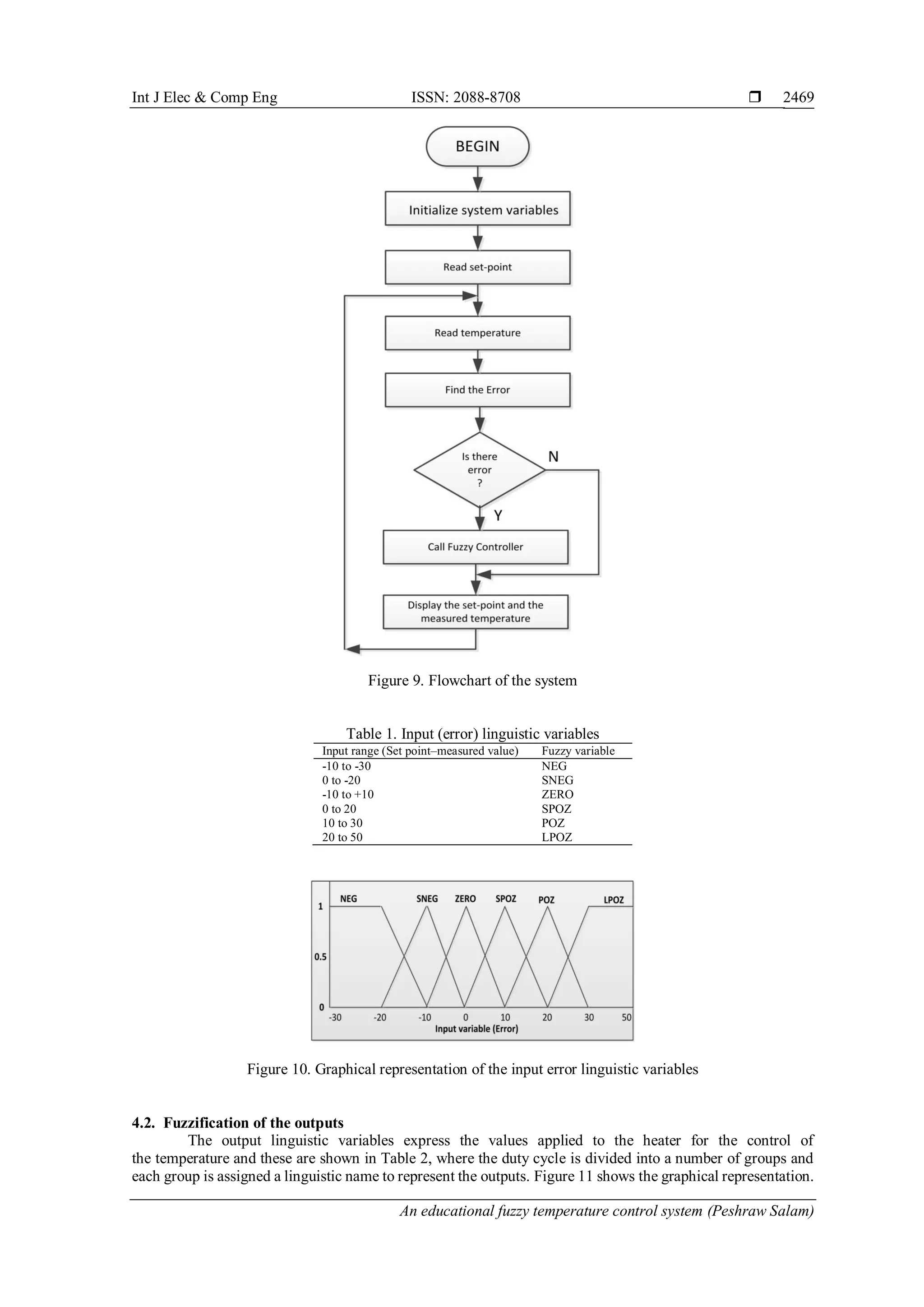
by the defuzzification process. Figure 9 shows the flowchart of the developed software where the process
continues forever until stopped manually by the user. The operation of various parts of the software in
the system is described in the remainder sections of the paper.
4.1. Fuzzification of the inputs
Fuzzy variables are not represented by numbers, but by linguistic terms [29, 30]. Triangular and
trapezoidal membership functions are frequently used to fuzzify the inputs and it is necessary to determine
the range of fuzzy variables related to the crisp inputs. Here, as shown in Table 1, the temperature range
from -10ºC to+50ºC is divided into a number of groups and each group is assigned a linguistic name to represent
the amount of error in the control algorithm. The following fuzzy variables are used to define the error which
is the difference between the set-point and the measured temperature: SNEG=small negative, NEG=negative,
ZERO=zero, SPOZ=small positive, POZ=positive, and LPOZ=large positive. Figure 10 shows the graphical
representation of the membership function for input error linguistic variables. Subprograms were written to
receive the crisp input values and range of fuzzy variables for membership functions and then return the degree
of the membership between 0 and 1.](https://image.slidesharecdn.com/v269dec24nov3apr19188ulfa-201208025212/75/An-educational-fuzzy-temperature-control-system-6-2048.jpg)
![ ISSN: 2088-8708
Int J Elec & Comp Eng, Vol. 10, No. 3, June 2020 : 2463 - 2473
2470
Here, the duty cycle of the voltage sent to the heater is the output variable. The following fuzzy membership
values were assigned for the output variable: ZE=zero, SM=small, ME=medium, SH=small high, HI=high,
VH=very high.
Table 2. Output (duty cycle) linguistic variables
Rule number Duty cycle Fuzzy variable
1 0 to 10 ZE
2 10 to 40 SM
3 25 to 55 ME
4 40 to 70 SH
5 55 to 85 HI
6 70 to 100 VH
Figure 11. Graphical representation of the output linguistic variables
4.3. Rule base
The rule base consists of the fuzzy rules in the form of IF...ELSE blocks where the IF part represents
the situation and the THEN part describes the response of the system. Table 3 shows the chosen fuzzy rules
for the system.
Table 3. Rule base
IF the input error is… THEN the duty cycle is…
NEG VH
SNEG HI
ZERO SH
SPOZ ME
POZ SM
LPOZ ZE
4.4. Defuzzification
The process of defuzzification gives a numeric value for the duty cycle to be used to power
the heater. There are many ways to carry out the defuzzification process [31, 32]. One of the popular ones, also
used in this paper is the weighted average defuzzification (or the center of mass defuzzification) technique
described by (9).
6
1
6
1
M Wi iidefuzz
Wii
(9)
where, iM is the value of the ith
output membership function, and iW is the weight described by the ith
rule
base. The calculated defuzzification output is used as the duty cycle to power the heater.](https://image.slidesharecdn.com/v269dec24nov3apr19188ulfa-201208025212/75/An-educational-fuzzy-temperature-control-system-8-2048.jpg)
![ ISSN: 2088-8708
Int J Elec & Comp Eng, Vol. 10, No. 3, June 2020 : 2463 - 2473
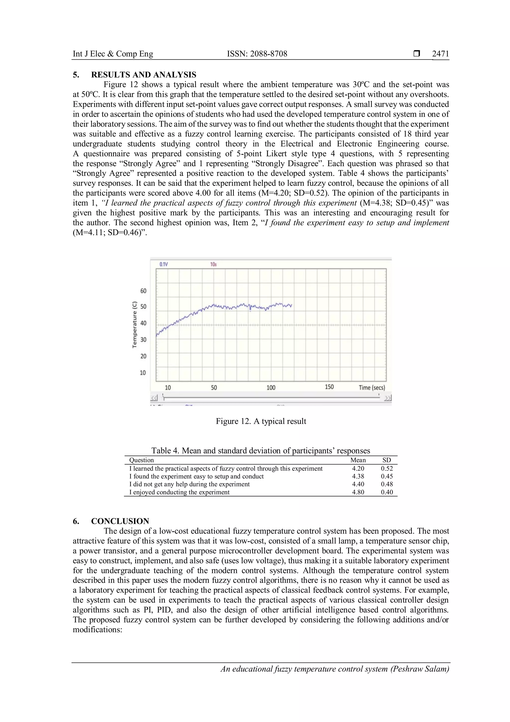
2472
The response time of the system is rather slow and it can make the students wait a long time before
the system settles down to its final value. A more powerful lamp can be used as a heater to accelerate
the system response. Additionally, the system response can also be improved by fitting the lamp and
the temperature sensor chip in an enclosed box. Currently the temperature set-point is hard-coded inside
the control algorithm. The system can be made more flexible and perhaps more user friendly by using
an external potentiometer to adjust the temperature set-point.
REFERENCES
[1] R.C. Dorf, and R.H. Bishop, Modern Control Systems, 13th
ed. London: Pearson, 2016.
[2] M. Elnour M, W.I.M. Taha, “PID and Fuzzy Logic in Temperature Control System,” Int. Conf. on Computing,
Electrical and Electronic Engineering (ICCEEE), Khartoum, Sudan, pp. 172-177, 2013.
[3] C.D. Johnson, Process Control Instrumentation Technology, 8th
ed. Essex: Pearson Education Ltd, 2014.
[4] J. Graf J., PID Control Fundamentals, CreateSpace Independent Publishing Platform, 2016.
[5] A. Purwar, D. Joshi, and M.S., “Dasgupta, Smart Control of Electric Lamp using Artificial Intelligence
basedController,” In Annual IEEE India Conference (INDICON), New Delhi, pp. 1-5, 2015
[6] F. He and C. Ma, “Modeling greenhouse air humidity by means of artificial neural network and principal component
analysis,” Comput and Electron Agric, vol. 71, pp. 19-23, 2010.
[7] N. Zotos et al., “Case study of a dimmable outdoor lighting system with intelligent and remote control,”
In Telecommunications and Multimedia (TEMU) International Conference, pp. 43-48, 2012.
[8] K. Raghupathy and R. K. Yadav, "Artificial intelligence in boiler control," 2015 International Conference on
Robotics, Automation, Control and Embedded Systems (RACE), Chennai, pp. 1-6, 2015.
[9] M. Outanoute et al., “Neural network dynamic model for temperature and relative humidity control under
greenhouse,” In Third International Workshop on RFID and Adaptive Wireless Sensor Networks (RAWSN), Agadir,
Morocco, 2015.
[10] E. Guney, M. Dursun and M. Demir, "Artificial neural network based real time speed control of a linear tubular
permanent magnet direct current motor," 2017 International Conference on Control, Automation and Diagnosis
(ICCAD), Hammamet, pp. 540-544, 2017.
[11] C. Sun, W. He, and J. Hong, “Neural Network Control of a Flexible Robotic Manipulator Using the Lumped Spring-
Mass Model,” IEEE Trans Syst Man Cybern Syst, vol. 47, no. 8, pp. 1863-1874, 2017.
[12] I.A. Belova, and M.V. Martinovich, “Neural network control algorithm for stand-alone solar cell electrical energy
conversion system,” In 16th
International Conference of Young Specialists on Micro/Nanotechnologies and Electron
Devices (EDM), Erlagol, Russia, 2015.
[13] W. Zhang and J. Qiao, “Direct adaptive neural network control for wastewater treatment process,” Proceeding of
the 11th World Congress on Intelligent Control and Automation, Shenyang, pp. 4003-4008, 2014.
[14] E.P. Dadios, “Fuzzy logic–Controls, Concepts,” Theories and Applications, Croatia: InTechOpen, 2012.
[15] L. Suganthi, S. Iniyan, and A.A. Samual, “Applications of fuzzy logic in renewable energy systems-A review,”
Renew Sust Energy Rev, vol. 48, pp. 585-607, 2015.
[16] S.K. Yadav, “DC Motor Position Control Using Fuzzy Proportional-Derivative Controllers With Different
Defuzzification Methods,” Journal of Electrical and Electronics Engineering (IOSR-JEEE), vol. 10, no. 1,
pp. 37-47, 2015.
[17] S. Birle, M.A. Hussein, and T. Becker, "Fuzzy logic control and soft sensing applications in food and beverage
processes," Food Control, vol. 29, no. 1, pp. 254-269, 2013.
[18] B. Srismrita B, “Realization of Fuzzy Logic Temperature Controller,” Int J of Emerging Technology and Advanced
Engineering, vol. 2, no. 6, 2012.
[19] M.I.H. Nour, J. Ooi, and K.Y. Chan, “Fuzzy logic control vs. conventional PID control of an inverted
pendulum robot,” Proceedings of 2007 ICIAS International Conference on Intelligent and Advanced Systems,
pp. 209-214, 2007.
[20] E. Natsheh, and K.A. Buragga, “Comparison between Conventional and Fuzzy Logic PID Controllers for Controlling
DC Motors,” Int J of Comput Sci, vol. 7, no. 5, pp. 128-134, 2010.
[21] G.S. Nhivekar, S.S. Nirmale, and R.R. Mudholker, “Implementation of fuzzy logic control algorithm in embedded
microcomputers for dedicated application,” Int J of Eng Sci and Techol, vol. 3, no. 4, pp. 276-283, 2011.
[22] “Temperature sensor-TMP36,” Sparkfun. [Online]. Available: https://www.sparkfun.com/products/10988.
[Accessed: 2-Dec-2017].
[23] D. Ibrahim, “Non-contact Temperature Measurement in Embedded Applications,” Electronics World,
vol. 123(1971), pp. 14-18, 2017.
[24] S. Mahadeokar, and M. Sardeshmukh, “Energy Efficient PWM Dimmable Smart Digital LED Driver,” International
Conference on Energy Systems and Applications (ICESA 2015), pp. 306-311, 2015.
[25] A.K. Dewangan, et al., “PWM Based Automatic Closed Loop Speed Control of DC Motor,” International Journal
of Engineering Trends and Technology, vol. 3, no. 2, pp. 110-112, 2012.
[26] RMS and Average Calculator, [Online], Available: http://www.daycounter.com/Calculators/RMS-Calculator.phtml.
[Accessed: 2-Dec-2017].
[27] “IRL520N data sheet,” International Rectifier, [Online], Available: http://www.irf.com. [Accessed: 21-Nov-2017].
[28] PIC18F45K22 Data sheet. [Online], Available: http://www.mikroe.com [Accessed: 12-Nov-2017].](https://image.slidesharecdn.com/v269dec24nov3apr19188ulfa-201208025212/75/An-educational-fuzzy-temperature-control-system-10-2048.jpg)
![Int J Elec & Comp Eng ISSN: 2088-8708
An educational fuzzy temperature control system (Peshraw Salam)
2473
[29] P.S. Krishna, Process Control Engineering, Delhi: IK International Publishing House, 2013.
[30] T. Uzunovic, and I. Turkovic, “Implementation of Microcontroller Based Fuzzy Controller,” 6th
IEEE International
Conference on Intelligent Systems, Sofia, Bulgaria, pp. 310-315, 2012.
[31] C.P. Ugale, et al., “DC-DC Converter Using Fuzzy Logic Controller,” International Research Journal of Engineering
and Technology (IRJET), vol. 2, no. 4, pp. 593-596, 2015.
[32] A.R. Patil, et al., “Embedded Fuzzy Module for Battery Charger Control,” Int J of Adv Res in Electr, Electron and
Instr. Eng., pp. 4072-4078, 2013.
BIOGRAPHIES OF AUTHORS
Peshraw S. Abdaladir graduated from the University of Human Development with a Bachelor’s
Degree in Computer Science and a Master’s Degree in Computer Information Systems from Near East
University in Cyprus. Peshraw S. Abdaladir currently works as a lecturer at the Department of Computer
Science at the University of Garmian.
Dogan Ibrahim graduated from Salford University with first class honours in electronic engineering.
He then completes MSc in automatic control engineering at the Manchester University. Prof Ibrahim
then completed his PhD in electrical engineering from the City University in London. Prof Ibrahim
worked in many industrial organizations before returning to the academic world. He has been
the Chairman of the department of computer engineering at the Near University. Prof Ibrahim is
the author of over 70 technical books published by well-known publishers. He is also the author of over
200 technical papers. Currently, Prof Ibrahim is retired and is working as a consultant.](https://image.slidesharecdn.com/v269dec24nov3apr19188ulfa-201208025212/75/An-educational-fuzzy-temperature-control-system-11-2048.jpg)


![[IJCT-V3I3P3] Authors: L.Navaneeth M.E, V.Rukkumani M.E.,Ph.D.,](https://cdn.slidesharecdn.com/ss_thumbnails/ijct-v3i3p3-160609074839-thumbnail.jpg?width=640&height=640&fit=bounds)


