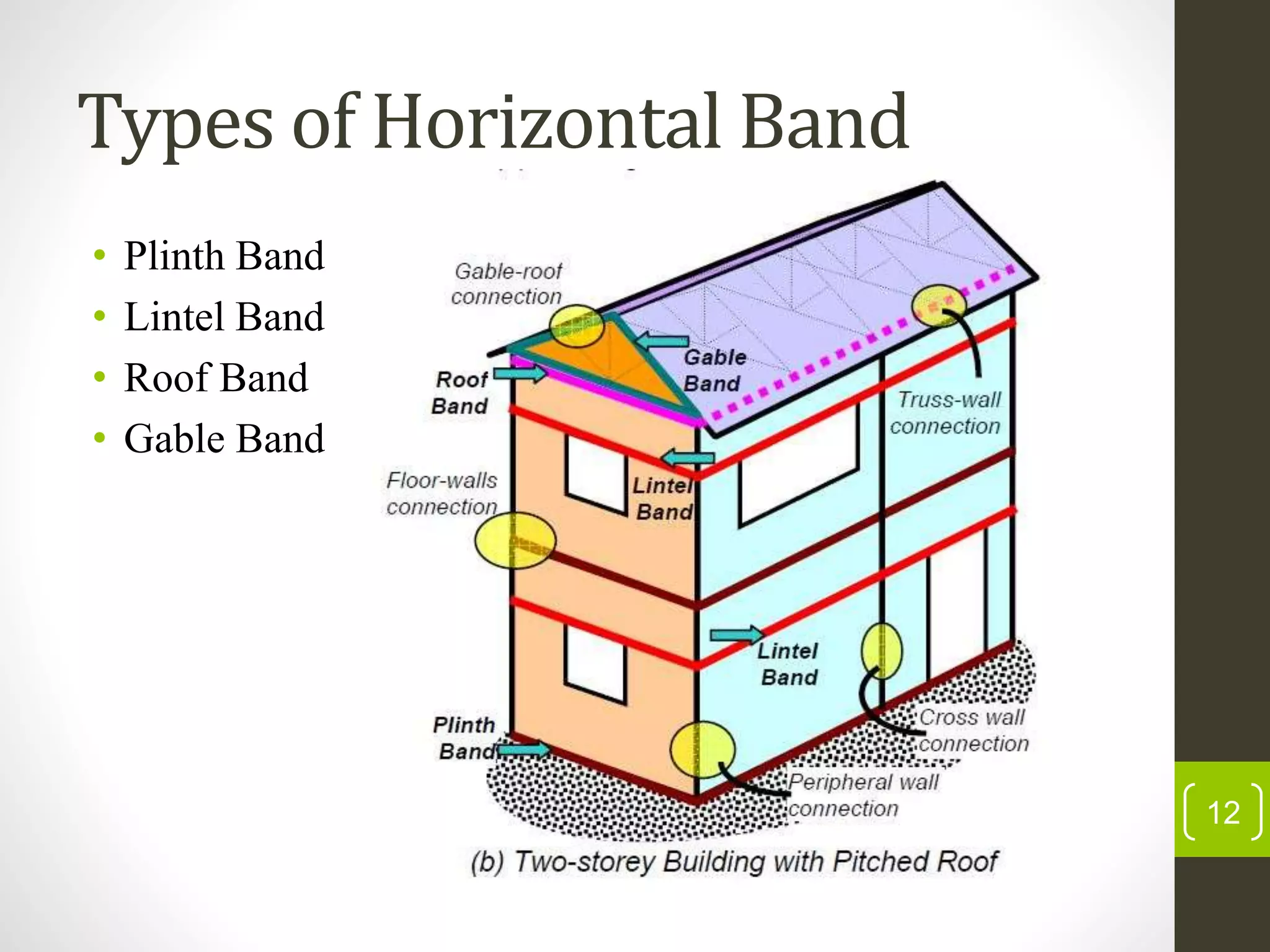
VISVESVARAYA TECHNOLOGICAL UNIVERSITY
Belagavi-590018
Technical Seminar on
LOW COST EARTHQUAKE RESISTANT
TECHNIQUES
In partial fulfillment of
BACHELOR OF ENGINEERING
In
CIVIL ENGINEERING
By
Mr. Sachin Kotian
(4MT14CV081)
Under the Guidance of
Mr . SAGAR S
Assistant Professor
Department of Civil Engineering
MANGALORE INSTITUTE OF TECHNOLOGYAND ENGINEERING
1
CONTENTS
• INTRODUCTION
• EARTHQUAKE : CAUSES,TYPES & EFFECTS
• VARIOUS TECHNIQUES ADOPTED
• CONCLUSION
• REFERENCES
2
INTRODUCTION
• Earthquake is a sudden release of extreme energy from
the earth crust resulting in shaking and displacement of
the ground along with the creation of seismic waves.
• It is the vibration of the ground due to the sudden release
of energy by the breaking and shifting of rock beneath the
Earth´s surface and it creates seismic waves.
3
Causes of Earthquake
• Geological Faults.
1. Normal Fault.
2. Thrust Fault.
3. Strike Slip Fault.
• Volcanic Eruptions.
• Mine Blasts.
• Nuclear Tests.
4
Seismic waves
• Seismic waves are generated by the release of energy
during an earthquake, which starts from focus of an
earthquake.
• Focus (Hypocenter): spot underground where the rock
begins to break.
• Epicenter: The location on the Earths surface directly
above the focus.
• Aftershock: Tremors that occur as rocks adjust to their
new position.
5
Types of Earthquake waves
Body waves : Spread outward from the focus in all
directions.
i. Primary Wave (P Wave)
ii. Secondary Wave (S Wave)
6
Surface waves : Spread outward from the epicenter to the Earth’s
surface .
• These waves are produced when earthquake energy reaches
the Earth's surface.
• Surface waves moves rock particles in a rolling and swaying
motion, so that the earth moves in different directions.
• These are the slowest moving waves, but are the most
destructive for structures on earth.
i. Love (L) wave
ii. Rayleigh wave
7
Effects of Earthquake
• If the Epicenter of a larger earthquake is situated in the
offshore (sea/ocean) seabed may be displaced sufficiently
to cause Tsunami.
• It also triggers land slides and occasionally volcanic
eruptions.
• Buildings may fall or sink into the soil.
• Rocks and soil may move downhill at a rapid rate.
8
The need for Earthquake
resistant structures
• It is designed to withstand the largest earthquake at
certain parts.
• The goal is to construct structures that fare better during
the seismic activity than their counterparts.
• To minimize the damage caused to the buildings there by
minimizing the causalities.
9
VARIOUS TECHNIQUES
• Horizontal Bands
• Base Isolation using waste tire pads
• Haunches
• Hollow raft foundation
10
Horizontal Band
• Horizontal band can be defined as a method of
reinforcing the masonry buildings by providing bands
with higher tensional strength.
• It is enabled in areas where two structural elements of a
building meets.
• It is also termed as seismic band which consist of
reinforced concrete running flat throughout all the
external and internal masonry wall elements.
11
Types of Horizontal Band
• Plinth Band
• Lintel Band
• Roof Band
• Gable Band
12
Base Isolation Using Waste
Tire Pads
• Seismic isolation or base isolation uncouples the structure
for the damaging effect of the ground motion.
• The main aim of this method is to increase lateral strength
of the structure and to increase ductility of structure.
• It is suitable for low to medium rise buildings rested on
hard soil underneath.
• Buildings rested on soft soils are not suitable for base
isolation.
13
Waste tire pads
• Waste tire pads or Scrap tires reduces the cost and weight of
the seismic base isolation pads.
• Rubber segments between reinforcement layers provide low
horizontal stiffness for the seismic base Isolation.
• Automobile tires are produced by means of vulcanized rubber
with steel mesh in different forms which have similar effects as
the steel plates.
• Since the tires are being designed for friction, load transfer
between scrap tire layers would be large enough to keep all
layers intact.
14
Application of Tire Pads
15
Haunches
• Haunches are provided to strengthen the joints.
• Haunches increase the lever arm at the connection point
thereby allowing a greater joint moment capacity.
• In seismic design they can be particularly useful in
allowing hinge formation in the beam as this is a safer
failure mode.
16
Hollow Raft Foundation
• Hollow Raft foundation is a deep foundation.
• It is used in the building construction on soft and weak
soil.
• It is designed in such a way that it behave as buoyant
(floating) substructure for the net loading over it.
• A hollow raft foundation fully filled with water can be
used to reduce destructible effects of earthquake.
• It might be filled with some viscous fluid, worked as
damper to reduce earth quake effects.
17
Fig:-Construction of a Buoyancy Raft or Hollow Raft
Foundation for a Building in Glasgow. 18
CONCLUSION
• The low cost methods can be effective only for the small
buildings, as the stories increase the design should be
made stronger.
• The waste material i.e., worn tires which are made up of
rubber ,can be piled together and strengthened and can be
effectively used as base isolation pads.
• Haunches increase the lever arm at the connection point
thereby allowing a greater joint moment capacity.
19
REFERENCES
1) Agarwal, P. and Shrikhande, M., 2006, Earthquake Resistant
Design of Structures, 2nd Edition, Prentice-Hall of India
Private Limited, New Delhi.
2) K. Sathishkumar, Study of Earthquake Resistant RCC
Buildings with Increased Strength and Stability. IJIRSET
Vol. 4, Issue 6, June 2015
3) Murty, C.V.R., 2004, IITK-BMTPC Earthquake Tip, New
Delhi.
4) Priestley,M.J.N., Seible,F., and Calvi,G.M., (1996), Seismic
Design and Retrofit of Bridges, John Wiley & Sons Inc, USA
5) Savita Devi, Satyam Mehta, Review Paper on Base Isolation
Method – The Best Retrofitting Technique. SSRG
International Journal of Civil Engineering (SSRG-IJCE) –
volume 3 Issue 5 – May 2016
6) Systems through Different Base Isolation Systems, Journal
of Earthquake Engineering, 7 (2), 223-250.
20
THANK YOU
21

LOW COST EARTHQUAKE RESISTANT TECHNIQUES

  • 1.
    VISVESVARAYA TECHNOLOGICAL UNIVERSITY Belagavi-590018 TechnicalSeminar on LOW COST EARTHQUAKE RESISTANT TECHNIQUES In partial fulfillment of BACHELOR OF ENGINEERING In CIVIL ENGINEERING By Mr. Sachin Kotian (4MT14CV081) Under the Guidance of Mr . SAGAR S Assistant Professor Department of Civil Engineering MANGALORE INSTITUTE OF TECHNOLOGYAND ENGINEERING 1
  • 2.
    CONTENTS • INTRODUCTION • EARTHQUAKE: CAUSES,TYPES & EFFECTS • VARIOUS TECHNIQUES ADOPTED • CONCLUSION • REFERENCES 2
  • 3.
    INTRODUCTION • Earthquake isa sudden release of extreme energy from the earth crust resulting in shaking and displacement of the ground along with the creation of seismic waves. • It is the vibration of the ground due to the sudden release of energy by the breaking and shifting of rock beneath the Earth´s surface and it creates seismic waves. 3
  • 4.
    Causes of Earthquake •Geological Faults. 1. Normal Fault. 2. Thrust Fault. 3. Strike Slip Fault. • Volcanic Eruptions. • Mine Blasts. • Nuclear Tests. 4
  • 5.
    Seismic waves • Seismicwaves are generated by the release of energy during an earthquake, which starts from focus of an earthquake. • Focus (Hypocenter): spot underground where the rock begins to break. • Epicenter: The location on the Earths surface directly above the focus. • Aftershock: Tremors that occur as rocks adjust to their new position. 5
  • 6.
    Types of Earthquakewaves Body waves : Spread outward from the focus in all directions. i. Primary Wave (P Wave) ii. Secondary Wave (S Wave) 6
  • 7.
    Surface waves :Spread outward from the epicenter to the Earth’s surface . • These waves are produced when earthquake energy reaches the Earth's surface. • Surface waves moves rock particles in a rolling and swaying motion, so that the earth moves in different directions. • These are the slowest moving waves, but are the most destructive for structures on earth. i. Love (L) wave ii. Rayleigh wave 7
  • 8.
    Effects of Earthquake •If the Epicenter of a larger earthquake is situated in the offshore (sea/ocean) seabed may be displaced sufficiently to cause Tsunami. • It also triggers land slides and occasionally volcanic eruptions. • Buildings may fall or sink into the soil. • Rocks and soil may move downhill at a rapid rate. 8
  • 9.
    The need forEarthquake resistant structures • It is designed to withstand the largest earthquake at certain parts. • The goal is to construct structures that fare better during the seismic activity than their counterparts. • To minimize the damage caused to the buildings there by minimizing the causalities. 9
  • 10.
    VARIOUS TECHNIQUES • HorizontalBands • Base Isolation using waste tire pads • Haunches • Hollow raft foundation 10
  • 11.
    Horizontal Band • Horizontalband can be defined as a method of reinforcing the masonry buildings by providing bands with higher tensional strength. • It is enabled in areas where two structural elements of a building meets. • It is also termed as seismic band which consist of reinforced concrete running flat throughout all the external and internal masonry wall elements. 11
  • 12.
    Types of HorizontalBand • Plinth Band • Lintel Band • Roof Band • Gable Band 12
  • 13.
    Base Isolation UsingWaste Tire Pads • Seismic isolation or base isolation uncouples the structure for the damaging effect of the ground motion. • The main aim of this method is to increase lateral strength of the structure and to increase ductility of structure. • It is suitable for low to medium rise buildings rested on hard soil underneath. • Buildings rested on soft soils are not suitable for base isolation. 13
  • 14.
    Waste tire pads •Waste tire pads or Scrap tires reduces the cost and weight of the seismic base isolation pads. • Rubber segments between reinforcement layers provide low horizontal stiffness for the seismic base Isolation. • Automobile tires are produced by means of vulcanized rubber with steel mesh in different forms which have similar effects as the steel plates. • Since the tires are being designed for friction, load transfer between scrap tire layers would be large enough to keep all layers intact. 14
  • 15.
  • 16.
    Haunches • Haunches areprovided to strengthen the joints. • Haunches increase the lever arm at the connection point thereby allowing a greater joint moment capacity. • In seismic design they can be particularly useful in allowing hinge formation in the beam as this is a safer failure mode. 16
  • 17.
    Hollow Raft Foundation •Hollow Raft foundation is a deep foundation. • It is used in the building construction on soft and weak soil. • It is designed in such a way that it behave as buoyant (floating) substructure for the net loading over it. • A hollow raft foundation fully filled with water can be used to reduce destructible effects of earthquake. • It might be filled with some viscous fluid, worked as damper to reduce earth quake effects. 17
  • 18.
    Fig:-Construction of aBuoyancy Raft or Hollow Raft Foundation for a Building in Glasgow. 18
  • 19.
    CONCLUSION • The lowcost methods can be effective only for the small buildings, as the stories increase the design should be made stronger. • The waste material i.e., worn tires which are made up of rubber ,can be piled together and strengthened and can be effectively used as base isolation pads. • Haunches increase the lever arm at the connection point thereby allowing a greater joint moment capacity. 19
  • 20.
    REFERENCES 1) Agarwal, P.and Shrikhande, M., 2006, Earthquake Resistant Design of Structures, 2nd Edition, Prentice-Hall of India Private Limited, New Delhi. 2) K. Sathishkumar, Study of Earthquake Resistant RCC Buildings with Increased Strength and Stability. IJIRSET Vol. 4, Issue 6, June 2015 3) Murty, C.V.R., 2004, IITK-BMTPC Earthquake Tip, New Delhi. 4) Priestley,M.J.N., Seible,F., and Calvi,G.M., (1996), Seismic Design and Retrofit of Bridges, John Wiley & Sons Inc, USA 5) Savita Devi, Satyam Mehta, Review Paper on Base Isolation Method – The Best Retrofitting Technique. SSRG International Journal of Civil Engineering (SSRG-IJCE) – volume 3 Issue 5 – May 2016 6) Systems through Different Base Isolation Systems, Journal of Earthquake Engineering, 7 (2), 223-250. 20
  • 21.