UNIT 2
Transmission Characteristicsof Optical Fibers
Attenuation – Absorption, Attenuation units, Attenuation – Scattering losses
Attenuation – Bending losses, microbending and macro bending losses, Attenuation - Core cladding losses
Signal distortion in optical waveguides, Types of dispersion-Intramodal and Intermodal dispersion
Material dispersion, Material dispersion, Waveguide dispersion
Waveguide dispersion, Signal distortion in single mode fibers
Polarization mode dispersion, Polarization mode dispersion, Intermodal dispersion
Intermodal dispersion, Solving Problems
Solving Problems, Pulse Broadening in Graded Index Waveguides
Mode Coupling, Design Optimization of Single Mode Fibers
2.
Attenuation
• Signal attenuation(also known as fiber loss or signal loss) as is one of the most
important properties of an optical fiber because it largely determines the maximum
unamplified or repeaterless separation between a transmitter and a receiver.
• Since amplifiers and repeaters are expensive to fabricate, install, and maintain, the
degree of attenuation in a fiber has a large influence on system cost.
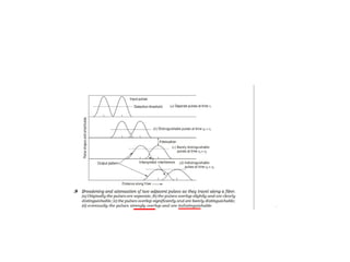
• Of equal importance is signal distortion.
• The distortion mechanisms in a fiber cause optical signal pulses to broaden as they travel
along a fiber.
• If these pulses travel sufficiently far, they will eventually overlap with neighboring
pulses, thereby creating errors in the receiver output.
• The signal distortion mechanisms thus limit the information-carrying capacity of a fiber.
3.
• Attenuation ofa light signal as it propagates along a fiber is an
important con sideration in the design of an optical communication
system; the degree of attenuation plays a major role in determining the
maximum transmission distance between a transmitter and a receiver
or an in-line amplifier.
• The basic attenuation mechanisms in a fiber are absorption, scattering,
and radiative losses of the optical energy.
• Absorption is related to the fiber material, whereas scattering is associated
both with the fiber material and with structural imperfections in the optical
waveguide
• Attenuation owing to radiative effects originates from perturbations (both
microscopic and macroscopic) of the fiber geometry.
4.
Attenuation Units
• Aslight travels along a fiber, its power decreases exponentially with distance.
• If P(0) is the optical power in a fiber at the origin (at z = 0), then the power
P(z) at a distance z farther down the fiber is
5.
• For simplicityin calculating optical signal attenuation in a fiber, the common
procedure is to express the attenuation coefficient in units of decibels per
kilometer, denoted by dB/km. Designating this parameter byα . This parameter
is generally referred to as the fi ber loss or the fi ber attenuation. It depends on
several variables
7.
Absorption
Absorption is causedby three different
mechanisms:
1.Absorption by atomic defects in the glass
composition.
2.Extrinsic absorption by impurity atoms in
the glass material.
3.Intrinsic absorption by the basic constituent
atoms of the fiber material
8.
• Atomic defectsare imperfections in the atomic structure of the fiber material.
Examples of these defects include missing molecules, high-density clusters of
atom groups, or oxygen defects in the glass structure.
• Usually, absorption losses arising from these defects are negligible compared
with intrinsic and impurity absorption effects.
• However, they can be significant if the fiber is exposed to ionizing radiation,
as might occur in a nuclear reactor environment, in medical radiation
therapies, in space missions that pass through the earth’s Van Allen belts, or in
accelerator instrumentation.
• In such applications, high radiation doses may be accumulated over several
years.
9.
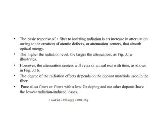
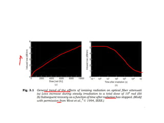
• The basicresponse of a fiber to ionizing radiation is an increase in attenuation
owing to the creation of atomic defects, or attenuation centers, that absorb
optical energy.
• The higher the radiation level, the larger the attenuation, as Fig. 3.1a
illustrates.
• However, the attenuation centers will relax or anneal out with time, as shown
in Fig. 3.1b.
• The degree of the radiation effects depends on the dopant materials used in the
fiber.
• Pure silica fibers or fibers with a low Ge doping and no other dopants have
the lowest radiation-induced losses.
10.
• The basicresponse of a fiber to ionizing radiation is an increase in attenuation
owing to the creation of atomic defects, or attenuation centers, that absorb
optical energy.
• The higher the radiation level, the larger the attenuation.
• However, the attenuation centers will relax or anneal out with time.
• The degree of the radiation effects depends on the dopant materials used in the
fiber. Pure silica fibers or fibers with a low Ge doping and no other dopants
have the lowest radiation-induced losses.
12.
Absorption
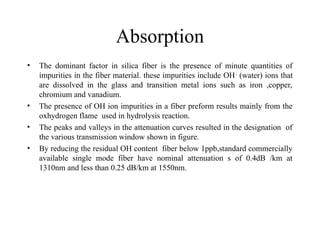
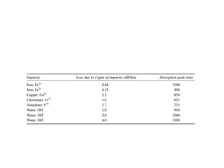
• The dominantfactor in silica fiber is the presence of minute quantities of
impurities in the fiber material. these impurities include OH-
(water) ions that
are dissolved in the glass and transition metal ions such as iron ,copper,
chromium and vanadium.
• The presence of OH ion impurities in a fiber preform results mainly from the
oxhydrogen flame used in hydrolysis reaction.
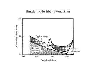
• The peaks and valleys in the attenuation curves resulted in the designation of
the various transmission window shown in figure.
• By reducing the residual OH content fiber below 1ppb,standard commercially
available single mode fiber have nominal attenuation s of 0.4dB /km at
1310nm and less than 0.25 dB/km at 1550nm.
13.
• Impurity absorptionlosses occur either because of electron transitions between
the energy levels within these ions or because of charge transitions between
ions.
• The absorption peaks of the various transition metal impurities tend to be
broad, and several peaks may overlap, which further broadens the absorption
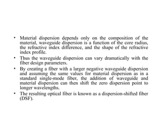
in a specific region.
• Modern vapor-phase fiber techniques for producing a fiber preform have
reduced the transition-metal impurity levels by several orders of magnitude.
Such low impurity levels allow the fabrication of low-loss fibers.
15.
• The presenceof OH ion impurities in a fi ber preform results mainly from the
oxyhydrogen flame used in the hydrolysis reaction of the SiCl4, GeCl4, and
POCl3 starting materials.
• Water impurity concentrations of less than a few parts per billion (ppb) are
required if the attenuation is to be less than 20 dB/km.
• The high levels of OH ions in early fibers resulted in large absorption peaks at
725, 950, 1240, and 1380 nm.
• Regions of low attention lie between these absorption peaks.
16.
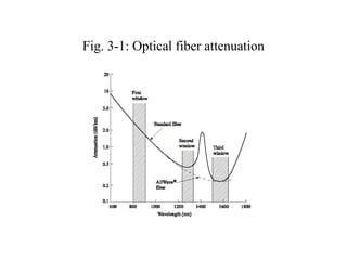
• The peaksand valleys in the attenuation curves resulted in the designation of
the various transmission windows shown in Fig.
• By reducing the residual OH content of fibers to below 1 ppb, standard
commercially available single-mode fibers have nominal attenuations of 0.4
dB/km at 1310 nm (in the O-band) and less than 0.25 dB/km at 1550 nm (in
the C-band).
• Further elimination of water ions diminishes the absorption peak around 1440
nm and thus opens up the E-band for data transmission, as indicated by the
dashed line in Fig.
• Optical fibers that can be used in the E-band are known by names such as low
water-peak or full-spectrum fibers.
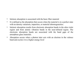
• Intrinsic absorptionis associated with the basic fiber material
• It is defined as the absorption that occurs when the material is in a perfect state
with no density variations, impurities, or material inhomogeneities.
• Intrinsic absorption results from electronic absorption bands in the ultra violet
region and from atomic vibration bands in the near-infrared region. The
electronic absorption bands are associated with the band gaps of the
amorphous glass materials.
• Absorption occurs when a photon inter acts with an electron in the valence
band and excites it to a higher energy level
19.
Scattering Losses
• Dueto microscopic variation in the material density
• Compositional fluctuation
• Structural inhomogeneities
• defects occurring during fiber manufacture
• Glass is composed of a randomly connected network of molecules. Such a
structure naturally contains regions in which the molecular density is either
higher or lower than the average density in the glass
• Glass made up of several oxides SiO2,GeO2,P2O5
• The above effects vary the refractive index variations which occur with in the
glass over distances that are small compared to the wavelengths.
• These index variations cause a Rayleigh-type scattering of the light. Rayleigh
scattering in glass is the same phenomenon that scatters light from the sun in
the atmosphere, thereby giving rise to a blue sky
20.
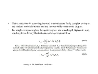
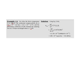
• The expressionsfor scattering-induced attenuation are fairly complex owing to
the random molecular nature and the various oxide constituents of glass.
• For single-component glass the scattering loss at a wavelength l (given in mm)
resulting from density fluctuations can be approximated by
23.
• Structural inhomogeneitiesand defects created during fiber fabrication can
also cause scattering of light out of the fiber.
• These defects may be in the form of trapped gas bubbles, unreacted starting
materials, and crystallized regions in the glass.
• In general, the preform manufacturing methods that have evolved have
minimized these extrinsic effects to the point where scattering that results
from them is negligible compared with the intrinsic Rayleigh scattering.
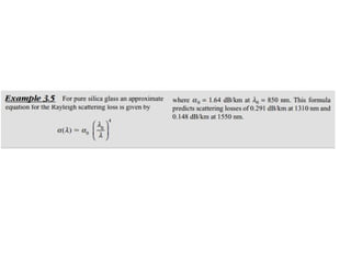
• Since Rayleigh scattering follows a characteristic dependence, it
decreases dramatically with increasing wavelength,
• The losses of multimode fibers are generally higher than those of single-mode
fibers.
• This is a result of higher dopant concentrations and the accompanying larger
scattering loss due to greater compositional fluctuation in multimode fibers.
• In addition, multimode fibers are subject to higher-order-mode losses owing
to perturbations at the core-cladding interface.
24.
Rayleigh Scattering
• Itoccurs because the molecules of silicon dioxide have some freedom when adjacent
to one another. Thus, setup at irregular positions and distances with respect to one
another when the glass is rapidly cooled during the final stage of the fabrication
process. Those structural variations are seen by light as variations in the refractive
index, thus causing the light to reflect – that is, to scatter – in different directions
• Rayleigh scattering is a scattering of light by particles much smaller than
the wavelength of the light, which may be individual atoms or molecules. Rayleigh
scattering is a process in which light is scattered by a small spherical volume of
variant refractive index, such as a particle, bubble, droplet, or even a density
fluctuation.
• As light travels in the core, it interacts with the silica molecules in the core.
Rayleigh scattering is the result of these elastic collisions between the light wave and
the silica molecules in the fiber. Rayleigh scattering accounts for about 96 percent of
attenuation in optical fiber
•
25.
Rayleigh Scattering
• Causesof Rayleigh Scattering:
• It results from non-ideal physical properties of the manufactured fiber.
• It results from inhomogeneities in the core and cladding.
• Because of these inhomogeneities problems occur like –
• a) Fluctuation in refractive index
• b) density and compositional variations.
Minimizing of Rayleigh Scattering:
• Rayleigh scattering is caused due to compositional variations which can be reduced by
improved fabrication.
Fiber Bending Loss
•Radiative losses occur whenever an optical fiber
undergoes a bend of finite radius of curvature.
• Fibers can be subject to two types of curvatures:
(a) macroscopic bends having radii that are large compared
with the fiber diameter, such as those that occur when a
fiber cable turns a corner
(b) random microscopic bends of the fiber axis that can arise
when the fibers are incorporated into cables.
29.
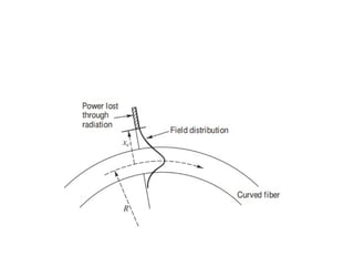
Macro Bending
• Forslight bends, the loss is extremely small and is not observed.
• As the radius of curvature decreases, the loss increases exponentially until at
a certain critical radius of curvature loss becomes observable.
• If the bend radius is made a bit smaller once this threshold point has been
reached, the losses suddenly become extremely large.
• It is known that any bound core mode has an evanescent field tail in the
cladding which decays exponentially as a function of distance from the core.
Since this field tail moves along with the field in the core, part of the energy of
a propagating mode travels in the fiber cladding.
• When a fiber is bent, the field tail on the far side of the centre of curvature
must move faster to keep up with the field in the core, for the lowest order
fiber mode.
• an evanescent field, or evanescent wave, is an oscillating electric and/or magnetic field
that does not propagate as an electromagnetic wave but whose energy is spatially
concentrated in the vicinity of the source (
30.
• At acertain critical distance xc, from the centre of the fiber;
the field tail would have to move faster than the speed of
light to keep up with the core field.
• Since this is not possible the optical energy in the field tail
beyond xc radiates away.
• The amount of optical radiation from a bent fiber depends
on the field strength at xc and on the radius of curvature R.
• Since higher order modes are bound less tightly to the fiber
core than lower order modes, the higher order modes will
radiate out of the fiber first.
31.
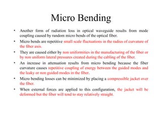
Micro Bending
• Anotherform of radiation loss in optical waveguide results from mode
coupling caused by random micro bends of the optical fiber.
• Micro bends are repetitive small scale fluctuations in the radius of curvature of
the fiber axis.
• They are caused either by non uniformities in the manufacturing of the fiber or
by non uniform lateral pressures created during the cabling of the fiber.
• An increase in attenuation results from micro bending because the fiber
curvature causes repetitive coupling of energy between the guided modes and
the leaky or non guided modes in the fiber.
• Micro bending losses can be minimized by placing a compressible jacket over
the fiber.
• When external forces are applied to this configuration, the jacket will be
deformed but the fiber will tend to stay relatively straight.
Cabling and Packaginglosses
• Non uniformities in the manufacturing of
the fiber by non uniform lateral pressure
during the cabling of fiber
34.
Core and claddinglosses
• The core and cladding have different
indices of refraction and therefore differ in
composition, the core and cladding
generally have different attenuation coeffi
cients, denoted α1 and α2 , respectively.
• The loss for a mode of order (n, m) for a
step-index waveguide is
35.
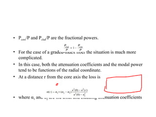
• Pcore/P andPclad/P are the fractional powers.
• For the case of a graded-index fiber the situation is much more
complicated.
• In this case, both the attenuation coefficients and the modal power
tend to be functions of the radial coordinate.
• At a distance r from the core axis the loss is
• where α1 and α2 are the axial and cladding attenuation coefficients
36.
Connector and Splicesloss
• Interconnection of different fiber lengths is a necessary requirement for the
assembly of complex fiber transmission and signal manipulation networks.
Whether via demountable, physical coupling (via connectorization) or by
irreversible splicing techniques (e.g. fusion splicing) alignment of the fiber
cores is critical to minimize losses associated with the connection.
• In a general sense, successful connections will minimize lateral offset of the
core centers, angular misalignment, tilt, and longitudinal displacement (i.e. the
formation of a gap).
• It is also possible that the two fibers to be joined have different absolute core
dimensions and varied core-clad diameter ratios as well as different core and
cladding glass compositions.
• An opticalsignal weakens from attenuation
mechanisms and broadens due to dispersion effects
as it travels along a fiber.
• Eventually these two factors will cause
neighboring pulses to overlap.
• After a certain amount of overlap occurs, the
receiver can no longer distinguish the individual
adjacent pulses and errors arise when interpreting
the received signal
40.
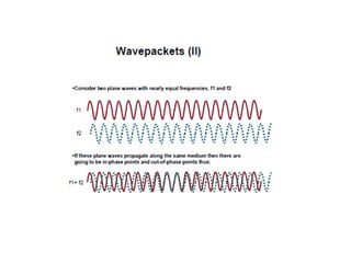
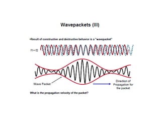
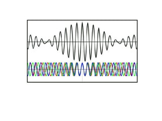
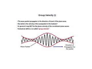
Types of Dispersion
•Signal dispersion is a consequence of factors such as
intermodal delay (also called intermodal dispersion),
intramodal dispersion, polarization-mode dispersion,
and higher-order dispersion effects.
• These distortions can be explained by examining the
behavior of the group velocities of the guided modes,
where the group velocity is the speed at which
energy in a particular mode travels along the fiber
41.
Intermodal delay
• Intermodaldelay (or simply modal delay)
appears only in multimode fibers.
• Modal delay is a result of each mode having
a different value of the group velocity at a
single frequency.
42.
Intramodal dispersion
• Intramodaldispersion or chromatic dispersion is pulse spreading that takes place within a single mode.
• This spreading arises from the finite spectral emission width of an optical source.
• The phenomenon also is known as group velocity dispersion, since the dispersion is a result of the group
velocity being a function of the wavelength.
• Because intramodal dispersion depends on the wavelength, its effect on signal distortion increases with the
spectral width of the light source.
• The spectral width is the band of wavelengths over which the source emits light.
• This wavelength band normally is characterized by the root-meansquare (rms) spectral width.
• Depending on the device structure of a light-emitting diode (LED), the spectral width is approximately 4 to 9
percent of a central wavelength.
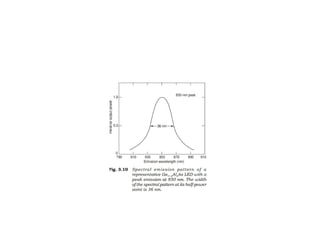
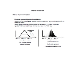
• For example, as Fig. illustrates, if the peak wavelength of an LED is 850 nm, a typical source spectral width
would be 36 nm; that is, such an LED emits most of its light in the 832-to-868-nm wavelength band.
• Laser diode optical sources exhibit much narrower spectral widths, with typical values being 1–2 nm for
multimode lasers and 10-4 nm for single-mode lasers
44.
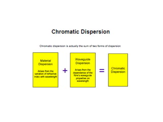
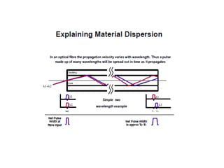
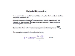
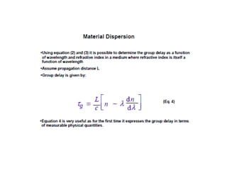
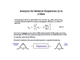
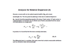
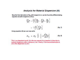
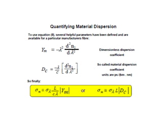
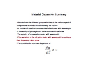
• The twomain causes of intramodal dispersion are as follows:
Material dispersion arises due to the variations of the refractive
index of the core material as a function of wavelength.
Material dispersion also is referred to as chromatic dispersion,
since this is the same effect by which a prism spreads out a
spectrum.
This refractive index property causes a wavelength dependence of
the group velocity of a given mode; that is, pulse spreading
occurs even when different wavelengths follow the same path.
46.
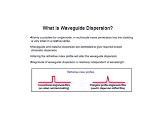
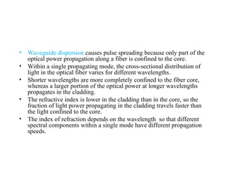
• Waveguide dispersioncauses pulse spreading because only part of the
optical power propagation along a fiber is confined to the core.
• Within a single propagating mode, the cross-sectional distribution of
light in the optical fiber varies for different wavelengths.
• Shorter wavelengths are more completely confined to the fiber core,
whereas a larger portion of the optical power at longer wavelengths
propagates in the cladding.
• The refractive index is lower in the cladding than in the core, so the
fraction of light power propagating in the cladding travels faster than
the light confined to the core.
• The index of refraction depends on the wavelength so that different
spectral components within a single mode have different propagation
speeds.
47.
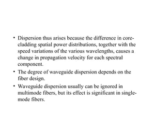
• Dispersion thusarises because the difference in core-
cladding spatial power distributions, together with the
speed variations of the various wavelengths, causes a
change in propagation velocity for each spectral
component.
• The degree of waveguide dispersion depends on the
fiber design.
• Waveguide dispersion usually can be ignored in
multimode fibers, but its effect is significant in single-
mode fibers.
49.
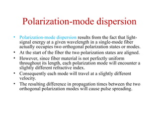
Polarization-mode dispersion
• Polarization-modedispersion results from the fact that light-
signal energy at a given wavelength in a single-mode fiber
actually occupies two orthogonal polarization states or modes.
• At the start of the fiber the two polarization states are aligned.
• However, since fiber material is not perfectly uniform
throughout its length, each polarization mode will encounter a
slightly different refractive index.
• Consequently each mode will travel at a slightly different
velocity.
• The resulting difference in propagation times between the two
orthogonal polarization modes will cause pulse spreading.
77.
Modal Delay
• Intermodaldispersion or modal delay appears only
in multimode fibers.
• This signal-distorting mechanism is a result of each
mode having a different value of the group velocity
at a single frequency.
• The steeper the angle of propagation of the ray
congruence, the higher is the mode number and,
consequently, the slower the axial group velocity.
• This variation in the group velocities of the different
modes results in a group delay spread, which is the
intermodal dispersion.
78.
Intermodal Dispersion
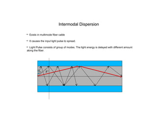
Existsin multimode fiber cable
It causes the input light pulse to spread.
Light Pulse consists of group of modes. The light energy is delayed with different amount
along the fiber.
79.
This dispersion mechanismis eliminated by single-mode operation but
is important in multimode fibers.
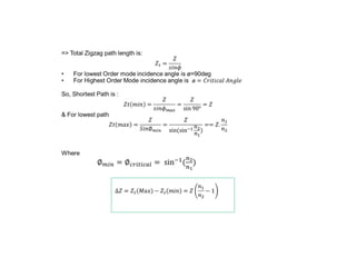
The maximum pulse broadening arising from the modal delay is the
difference between the travel time Tmax of the longest ray congruence
paths (the highest-order mode) and the travel time Tmin of the shortest
ray congruence paths (the fundamental mode).
This broadening is simply obtained from ray tracing and for a fiber of
length L is given by
80.
• The fibercapacity is specified in terms of
the bit rate-distance product BL, that is, the
bit rate times the possible transmission
distance L. In order for neighboring signal
pulses to remain distinguishable at the
receiver, the pulse spread should be less than
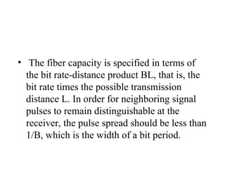
1/B, which is the width of a bit period.
82.
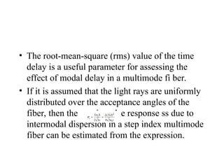
• The root-mean-square(rms) value of the time
delay is a useful parameter for assessing the
effect of modal delay in a multimode fi ber.
• If it is assumed that the light rays are uniformly
distributed over the acceptance angles of the
fiber, then the rms impulse response ss due to
intermodal dispersion in a step index multimode
fiber can be estimated from the expression.
83.
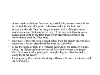
• A successfultechnique for reducing modal delay in multimode fibers
is through the use of a graded refractive index in the fiber core.
• In any multimode fiber the ray paths associated with higher-order
modes are concentrated near the edge of the core and thus follow a
longer path through the fiber than lower-order modes (which are
concentrated near the fiber axis).
• However, if the core has a graded index, then the higher-order modes
encounter a lower refractive index near the core edge.
• Since the speed of light in a material depends on the refractive index
value, the higher-order modes travel faster in the outer core region
than those modes that propagate through a higher refractive index
along the fi ber center.
• Consequently this reduces the delay difference between the fastest and
slowest modes.
84.
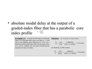
• absolute modaldelay at the output of a
graded-index fiber that has a parabolic core
index profile
92.
Birefringence in single-modefibers
Because of asymmetries the refractive indices for the two degenerate modes (vertical &
horizontal polarizations) are different. This difference is referred to as birefringence,
: f
B
Optical Fiber communications, 3rd
ed.,G.Keiser,McGrawHill, 2000
93.
Fiber Beat Length
Ingeneral, a linearly polarized mode is a combination of both of the degenerate modes. As the modal
wave travels along the fiber, the difference in the refractive indices would change the phase
difference between these two components & thereby the state of the polarization of the mode.
However after certain length referred to as fiber beat length, the modal wave will produce its
original state of polarization. This length is simply given by:
f
p
kB
L
2
[2-35]
Intermodal Dispersion
Existsin multimode fiber cable
It causes the input light pulse to spread.
Light Pulse consists of group of modes. The light energy is delayed with different amount
along the fiber.
97.
Graded Index Fiber
Structure
•In graded index fiber, core refractive index
decreases continuously with increasing
radial distance r from center of fiber and
constant in cladding
• α defines the shape of the index profile
• As α goes to infinity, above reduces to step
index
• The index difference is
a
r
for
n
n
n
a
r
for
a
r
n
r
n
2
1
2
/
1
1
2
/
1
1
)
1
(
)
2
1
(
0
]
)
(
2
1
[
)
(
1
2
1
2
1
2
2
2
1
2 n
n
n
n
n
n
98.
contd
• NA ismore complex than step index fiber
since it is function of position across the
core
• Geometrical optics considerations show
that light incident on fiber core at position
r will propagate only if it within NA(r)
• Local numerical aperture is defined as
• And
0
0
)
/
(
1
)
0
(
]
)
(
[
)
(
2
/
1
2
2
2
r
for
for
a
r
NA
n
r
n
r
NA
2
]
)
0
(
[
)
0
( 1
2
/
1
2
2
2
1
2
/
1
2
2
2
n
n
n
n
n
NA
99.
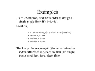
Examples
If a =9.5 micron, find n2 in order to design a
single mode fiber, if n1=1.465.
Solution,
The longer the wavelength, the larger refractive
index difference is needed to maintain single
mode condition, for a given fiber
458
.
1
,
1550
46
.
1
,
1300
463
.
1
,
820
465
.
1
)
/
25
.
4
2
(
)
/
2
(
405
.
2
2
2
2
2
2
2
2
2
2
1
n
nm
n
nm
n
nm
n
n
n
a
V
100.
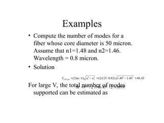
Examples
• Compute thenumber of modes for a
fiber whose core diameter is 50 micron.
Assume that n1=1.48 and n2=1.46.
Wavelength = 0.8 micron.
• Solution
For large V, the total number of modes
supported can be estimated as
45
.
46
46
.
1
48
.
1
)
82
.
0
/
25
2
(
)
/
2
( 2
2
2
2
2
1
82
.
0
n
n
a
V m
1079
2
/
45
.
46
2
/ 2
2
V
M
101.
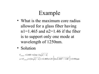
Example
• What isthe maximum core radius
allowed for a glass fiber having
n1=1.465 and n2=1.46 if the fiber
is to support only one mode at
wavelength of 1250nm.
• Solution
m
x
n
n
V
a
n
n
a
V
critical
critical
956
.
3
46
.
1
465
.
1
2
/
25
.
1
405
.
2
)
2
/(
)
/
2
(
405
.
2
2
2
2
2
2
1
2
2
2
1
102.
The basic designand operational
characteristics of single-mode fibers.
103.
In the designof single-mode fibers, two
factors are to be considered. These are
i) dispersion (ii) attenuation
For silica-based fibers the dispersion
minimum is around 1.3 mm, whereas the
attenuation minimum is around 1.55 mm
104.
• For anideal design, the dispersion minimum should be
at the attenuation minimum.
• In order to optimize the performance of single-mode
fibers, therefore, a number of designs with different
refractive index profiles for the core and cladding have
been investigated.
• The designs may be grouped into four categories:
(i) standard or conventional 1.3-mm optimized fibers
(ii) dispersion-shifted fibers (DSFs)
(iii) dispersion-flattened fibers (DFFs)
(iv) large effective area fibers (LEAFs)
105.
Dispersion Shifted Fiber
•Dispersion Shifted Fiber is a type of single-mode optical
fiber with a core-clad index profile tailored to shift the zero-
dispersion wavelength from the natural 1300 nm in silica-
glass fibers to the minimum-loss window at 1550 nm.
• The group velocity or intramodal dispersion which
dominates in single-mode fibers includes both material
and waveguide dispersion.
• Waveguide dispersion can be made more negative by
changing the index profile and thus be used to offset the
fixed material dispersion, shifting or flattening the overall
intramodal dispersion.
• This is advantageous because it allows a communication
system to possess both low dispersion and low
attenuation.
106.
Large effective areafibers
• A singlemode, non-zero dispersion-shifted
fiber with an effective area of 72
• A singlemode, non-zero dispersion-shifted
fiber with an effective area of 72 µm2
reduces
nonlinear effects in long-haul transmission
systems.
• Large Effective Area Fiber (LEAF) is designed
for use with dense WDM systems operating in
the 1550 nm window at 10 Gbit/s.
107.
dispersion-flattened fibers
(DFFs)
• Atype of Glass optical Fiber
providing low pulse Dispersion over
a broad portion of the Light spectrum.
This means it can operate at 1300-nm
and 1550-nm wavelengths
simultaneously.
108.
Refractive-Index Profiles
• Whencreating single-mode fibers, manufacturers pay special attention
to how the fiber design affects both chromatic and polarization-mode
dispersions.
• Such considerations are important because these dispersions set the
limits on long-distance and high-speed data transmission.
• The chromatic dispersion of a step-index silica fiber is lowest at 1310
nm. However, if the goal is to transmit a signal as far as possible, it is
better to operate the link at 1550 nm (in the C-band) where the fiber
attenuation is lower.
• For high-speed links the C-band presents a problem because
chromatic dispersion is much larger at 1550 nm than at 1310 nm.
• Consequently, fiber designers devised methods for adjusting the fiber
parameters to shift the zero-dispersion point to longer wavelengths.
109.
• The basicmaterial dispersion is hard to alter significantly.
• However, it is possible to modify the waveguide dispersion by
changing from a simple step-index design to more complex
index profiles for the cladding, thereby creating different
chromatic-dispersion characteristics in single-mode fibers.
• Popular single-mode fibers that are used widely in
telecommunication networks are near-step-index fibers, which
are optimized for use in the O-band around 1310 nm.
• These 1310-nm-optimized single mode fibers are of either the
matched-cladding or the depressed-cladding
110.
• Matched-cladding fibershave a uniform refractive index
throughout the cladding.
• Typical mode-field diameters are 9.5 mm and the core-to-
cladding index differences are around 0.35 percent.
• In depressed-cladding fibers the cladding material next to
the core has a lower index than the outer cladding region.
• Mode-field diameters are around 9.0 mm, and typical
positive and negative index differences are 0.25 and 0.12
percent, respectively
111.
• Material dispersiondepends only on the composition of the
material, waveguide dispersion is a function of the core radius,
the refractive index difference, and the shape of the refractive
index profile.
• Thus the waveguide dispersion can vary dramatically with the
fiber design parameters.
• By creating a fiber with a larger negative waveguide dispersion
and assuming the same values for material dispersion as in a
standard single-mode fiber, the addition of waveguide and
material dispersion can then shift the zero dispersion point to
longer wavelengths.
• The resulting optical fiber is known as a dispersion-shifted fiber
(DSF).
112.
• The largercore areas reduce the effects of fiber nonlinearities,
which limit system capacities of transmission systems that have
densely spaced WDM channels.
• Whereas standard single-mode fibers have effective core areas
of about 55 mm2
, these profiles yield values greater than 100
mm2
.
• An alternative fiber design concept is to distribute the dispersion
minimum over a wider spectral range.
• This approach is known as dispersion flattening. Dispersion-
flattened fibers are more complex to design than dispersion-
shifted fibers, because dispersion must be considered over a
much broader range of wavelengths
113.
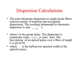
Dispersion Calculations
• Thetotal chromatic dispersion in single-mode fibers
consists mainly of material and waveguide
dispersions. The resultant intramodal or chromatic
dispersion is represented by
• where t is the group delay. The dispersion is
commonly expressed in ps /(nm . km). The
broadening of an optical pulse over a fiber of length
L is given by
• where is the half-power spectral width of the
optical source.
114.
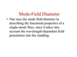
Mode-Field Diameter
• Oneuses the mode field diameter in
describing the functional properties of a
single-mode fiber, since it takes into
account the wavelength-dependent field
penetration into the cladding.
115.
Bending Loss
• Macrobending and micro bending losses are important
in the design of single-mode fibers.
• These losses are principally evident in the 1550-nm
region and show up as a rapid increase in attenuation
when the fiber is bent smaller than a certain bend radius.
• The lower the cutoff wavelength relative to the operating
wavelength, the more susceptible single-mode fibers are
to bending.
• The bending losses are primarily a function of the mode-
field diameter. Generally, the smaller the mode-field
diameter (i.e., the tighter the confinement of the mode to
the core), the smaller the bending loss
116.
• By specifyingbend-radius limitations when installing standard
single-mode fibers, one can largely avoid high micro bending
losses.
• Manufacturers usually recommend a fiber or cable bend
diameter no smaller than 40–50 mm
• This is consistent with bend diameter limitations of 50–75 mm
specified by installation guides for cable placement in ducts,
fiber-splice enclosures, and equipment racks.
• The development of bend-insensitive fibers allows much tighter
coiling of these fibers in optoelectronic packages. In addition,
use of these bend-insensitive fibers in jumper cables greatly
reduces bending loss effects when they are installed in highly
confined equipment racks.


![Fiber Beat Length
In general, a linearly polarized mode is a combination of both of the degenerate modes. As the modal
wave travels along the fiber, the difference in the refractive indices would change the phase
difference between these two components & thereby the state of the polarization of the mode.
However after certain length referred to as fiber beat length, the modal wave will produce its
original state of polarization. This length is simply given by:
f
p
kB
L
2
[2-35]](https://image.slidesharecdn.com/unit2fooppt-250727111424-98b6474c/85/FIBER-OPTICS-AND-CHARACTERISTICS-STUDY-ppt-93-320.jpg)
![Graded Index Fiber
Structure
• In graded index fiber, core refractive index
decreases continuously with increasing
radial distance r from center of fiber and
constant in cladding
• α defines the shape of the index profile
• As α goes to infinity, above reduces to step
index
• The index difference is
a
r
for
n
n
n
a
r
for
a
r
n
r
n
2
1
2
/
1
1
2
/
1
1
)
1
(
)
2
1
(
0
]
)
(
2
1
[
)
(
1
2
1
2
1
2
2
2
1
2 n
n
n
n
n
n
](https://image.slidesharecdn.com/unit2fooppt-250727111424-98b6474c/85/FIBER-OPTICS-AND-CHARACTERISTICS-STUDY-ppt-97-320.jpg)
![contd
• NA is more complex than step index fiber
since it is function of position across the
core
• Geometrical optics considerations show
that light incident on fiber core at position
r will propagate only if it within NA(r)
• Local numerical aperture is defined as
• And
0
0
)
/
(
1
)
0
(
]
)
(
[
)
(
2
/
1
2
2
2
r
for
for
a
r
NA
n
r
n
r
NA
2
]
)
0
(
[
)
0
( 1
2
/
1
2
2
2
1
2
/
1
2
2
2
n
n
n
n
n
NA](https://image.slidesharecdn.com/unit2fooppt-250727111424-98b6474c/85/FIBER-OPTICS-AND-CHARACTERISTICS-STUDY-ppt-98-320.jpg)