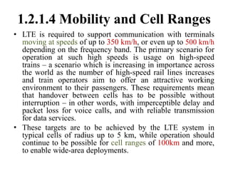
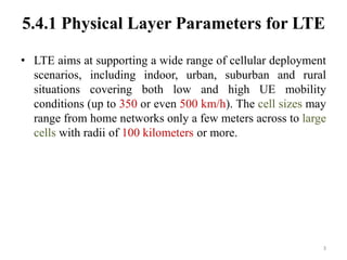
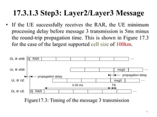
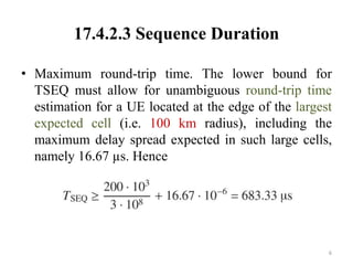
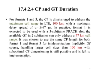
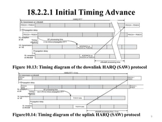
Long Range Cell Coverage for LTE
Yi-Hsueh Tsai
lucas@iii.org.tw
1
1.2.1.4 Mobility and Cell Ranges
• LTE is required to support communication with terminals
moving at speeds of up to 350 km/h, or even up to 500 km/h
depending on the frequency band. The primary scenario for
operation at such high speeds is usage on high-speed
trains – a scenario which is increasing in importance across
the world as the number of high-speed rail lines increases
and train operators aim to offer an attractive working
environment to their passengers. These requirements mean
that handover between cells has to be possible without
interruption – in other words, with imperceptible delay and
packet loss for voice calls, and with reliable transmission
for data services.
• These targets are to be achieved by the LTE system in
typical cells of radius up to 5 km, while operation should
continue to be possible for cell ranges of 100km and more,
to enable wide-area deployments.
5.4.1 Physical Layer Parameters for LTE
• LTE aims at supporting a wide range of cellular deployment
scenarios, including indoor, urban, suburban and rural
situations covering both low and high UE mobility
conditions (up to 350 or even 500 km/h). The cell sizes may
range from home networks only a few meters across to large
cells with radii of 100 kilometers or more.
3
17.3.1.3 Step3: Layer2/Layer3 Message
• If the UE successfully receives the RAR, the UE minimum
processing delay before message 3 transmission is 5ms minus
the round-trip propagation time. This is shown in Figure 17.3
for the case of the largest supported cell size of 100km.
4
Figure17.3: Timing of the message 3 transmission
17.4.2.2 PRACH Formats
• Four Random Access preamble formats are defined for
Frequency Division Duplex (FDD) operation. Each format is
defined by the durations of the sequence and its CP, as listed
in Table17.1. The format configured in a cell is broadcast in
the System Information.
5
Table17.1: Random access preamble formats.
17.4.2.3 Sequence Duration
• Maximum round-trip time. The lower bound for
TSEQ must allow for unambiguous round-trip time
estimation for a UE located at the edge of the largest
expected cell (i.e. 100 km radius), including the
maximum delay spread expected in such large cells,
namely 16.67 µs. Hence
6
17.4.2.4 CP and GT Duration
• For formats 1 and 3, the CP is dimensioned to address the
maximum cell range in LTE, 100 km, with a maximum
delay spread of d≈16.67 µs. In practice, format 1 is
expected to be used with a 3-subframe PRACH slot; the
available GT in 2 subframes can only address a 77 km cell
range. It was chosen to use the same CP length for both
format 1 and format 3 for implementations implicitly. Of
course, handling larger cell sizes than 100 km with
suboptimal CP dimensioning is still possible and is left to
implementation.
7
18.2.2.1 Initial Timing Advance
• After a UE has first synchronized its receiver to the
downlink transmissions received from the eNodeB (see
Section 7.2), the initial timing advance is set by means of
the random access procedure described in Section 17.3. This
involves the UE transmitting a random access preamble
from which the eNodeB estimates the uplink timing and
responds with an 11-bit initial timing advance command
contained within the Random Access Response (RAR)
message. This allows the timing advance to be configured
by the eNodeB with a granularity of 0.52 µs from 0 up to a
maximum of 0.67 ms,1 corresponding to a cell radius of
100km.
8
18.2.2.1 Initial Timing Advance
9
Figure 10.13: Timing diagram of the downlink HARQ (SAW) protocol
Figure10.14: Timing diagram of the uplink HARQ (SAW) protocol
18.2.2.1 Initial Timing Advance
• The timing advance was limited to this range in order to
avoid further restricting the processing time available at the
UE between receiving the downlink signal and having to
make a corresponding uplink transmission (see Figures
10.13 and 10.14). In any case, a cell range of 100 km is
sufficient for most practical scenarios, and is far beyond
what could be achieved with the early versions of GSM, in
which the range of the timing advance restricted the cell
range to about 35 km. Support of cell sizes even larger than
100 km in LTE is left to the eNodeB implementation to
handle.
10
23.4.1 Accommodation of Transmit–
Receive Switching
• The LTE specifications support a set of guard period durations
ranging (non- contiguously) from 1 to 10 OFDM symbols for
the normal CP (or from 1 to 8 OFDM symbols for the
extended CP). A duration of 1 OFDM symbol should be
sufficient for many of the anticipated cellular deployments of
LTE (up to around 2 km nominal cell radius for γ =2), whereas
at the other end of the scale, guard period durations of the
order of 700 µs support one-way propagation-path delays of
the order of 100km.
11
References
1) LTE The UMTS Long Term Evolution from Theory
to Practice Ed2
12

Long Range Cell Coverage for LTE

  • 1.
    Long Range CellCoverage for LTE Yi-Hsueh Tsai lucas@iii.org.tw 1
  • 2.
    1.2.1.4 Mobility andCell Ranges • LTE is required to support communication with terminals moving at speeds of up to 350 km/h, or even up to 500 km/h depending on the frequency band. The primary scenario for operation at such high speeds is usage on high-speed trains – a scenario which is increasing in importance across the world as the number of high-speed rail lines increases and train operators aim to offer an attractive working environment to their passengers. These requirements mean that handover between cells has to be possible without interruption – in other words, with imperceptible delay and packet loss for voice calls, and with reliable transmission for data services. • These targets are to be achieved by the LTE system in typical cells of radius up to 5 km, while operation should continue to be possible for cell ranges of 100km and more, to enable wide-area deployments.
  • 3.
    5.4.1 Physical LayerParameters for LTE • LTE aims at supporting a wide range of cellular deployment scenarios, including indoor, urban, suburban and rural situations covering both low and high UE mobility conditions (up to 350 or even 500 km/h). The cell sizes may range from home networks only a few meters across to large cells with radii of 100 kilometers or more. 3
  • 4.
    17.3.1.3 Step3: Layer2/Layer3Message • If the UE successfully receives the RAR, the UE minimum processing delay before message 3 transmission is 5ms minus the round-trip propagation time. This is shown in Figure 17.3 for the case of the largest supported cell size of 100km. 4 Figure17.3: Timing of the message 3 transmission
  • 5.
    17.4.2.2 PRACH Formats •Four Random Access preamble formats are defined for Frequency Division Duplex (FDD) operation. Each format is defined by the durations of the sequence and its CP, as listed in Table17.1. The format configured in a cell is broadcast in the System Information. 5 Table17.1: Random access preamble formats.
  • 6.
    17.4.2.3 Sequence Duration •Maximum round-trip time. The lower bound for TSEQ must allow for unambiguous round-trip time estimation for a UE located at the edge of the largest expected cell (i.e. 100 km radius), including the maximum delay spread expected in such large cells, namely 16.67 µs. Hence 6
  • 7.
    17.4.2.4 CP andGT Duration • For formats 1 and 3, the CP is dimensioned to address the maximum cell range in LTE, 100 km, with a maximum delay spread of d≈16.67 µs. In practice, format 1 is expected to be used with a 3-subframe PRACH slot; the available GT in 2 subframes can only address a 77 km cell range. It was chosen to use the same CP length for both format 1 and format 3 for implementations implicitly. Of course, handling larger cell sizes than 100 km with suboptimal CP dimensioning is still possible and is left to implementation. 7
  • 8.
    18.2.2.1 Initial TimingAdvance • After a UE has first synchronized its receiver to the downlink transmissions received from the eNodeB (see Section 7.2), the initial timing advance is set by means of the random access procedure described in Section 17.3. This involves the UE transmitting a random access preamble from which the eNodeB estimates the uplink timing and responds with an 11-bit initial timing advance command contained within the Random Access Response (RAR) message. This allows the timing advance to be configured by the eNodeB with a granularity of 0.52 µs from 0 up to a maximum of 0.67 ms,1 corresponding to a cell radius of 100km. 8
  • 9.
    18.2.2.1 Initial TimingAdvance 9 Figure 10.13: Timing diagram of the downlink HARQ (SAW) protocol Figure10.14: Timing diagram of the uplink HARQ (SAW) protocol
  • 10.
    18.2.2.1 Initial TimingAdvance • The timing advance was limited to this range in order to avoid further restricting the processing time available at the UE between receiving the downlink signal and having to make a corresponding uplink transmission (see Figures 10.13 and 10.14). In any case, a cell range of 100 km is sufficient for most practical scenarios, and is far beyond what could be achieved with the early versions of GSM, in which the range of the timing advance restricted the cell range to about 35 km. Support of cell sizes even larger than 100 km in LTE is left to the eNodeB implementation to handle. 10
  • 11.
    23.4.1 Accommodation ofTransmit– Receive Switching • The LTE specifications support a set of guard period durations ranging (non- contiguously) from 1 to 10 OFDM symbols for the normal CP (or from 1 to 8 OFDM symbols for the extended CP). A duration of 1 OFDM symbol should be sufficient for many of the anticipated cellular deployments of LTE (up to around 2 km nominal cell radius for γ =2), whereas at the other end of the scale, guard period durations of the order of 700 µs support one-way propagation-path delays of the order of 100km. 11
  • 12.
    References 1) LTE TheUMTS Long Term Evolution from Theory to Practice Ed2 12