This document provides an overview of the 3GPP Long Term Evolution (LTE) physical layer. Key points include:
- LTE uses OFDM on the downlink and SC-FDMA on the uplink to provide peak data rates of 100 Mbps downlink and 50 Mbps uplink.
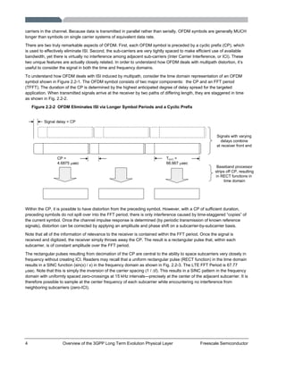
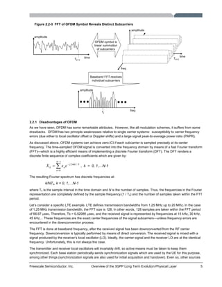
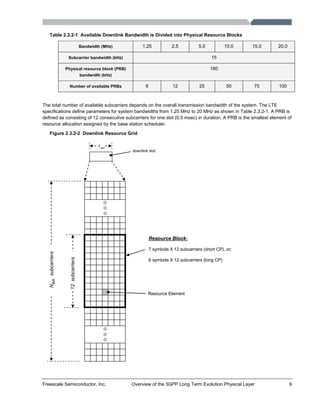
- OFDM divides the available bandwidth into multiple narrow subcarriers to combat multipath interference and eliminate inter-symbol interference.
- The document discusses technologies like OFDMA, MIMO, and the LTE frame structure in depth.
- The physical layer supports scalable bandwidths from 1.25 MHz to 20 MHz and multiple antenna configurations on uplink and downlink.
-
![Freescale Semiconductor, Inc. Overview of the 3GPP Long Term Evolution Physical Layer 1
1 Introduction
The 3GPP Long Term Evolution (LTE) represents a major advance in cellular technology. LTE is designed to meet
carrier needs for high-speed data and media transport as well as high-capacity voice support well into the next decade.
It encompasses high-speed data, multimedia unicast and multimedia broadcast services. Although technical
specifications are not yet finalized, significant details are emerging. This paper focuses on the LTE physical layer
(PHY).
The LTE PHY is a highly efficient means of conveying both data and control information between an enhanced base
station (eNodeB) and mobile user equipment (UE). The LTE PHY employs some advanced technologies that are new
to cellular applications. These include Orthogonal Frequency Division Multiplexing (OFDM) and Multiple Input Multiple
Output (MIMO) data transmission. In addition, the LTE PHY uses Orthogonal Frequency Division Multiple Access
(OFDMA) on the downlink (DL) and Single Carrier – Frequency Division Multiple Access (SC-FDMA) on the uplink (UL).
OFDMA allows data to be directed to or from multiple users on a subcarrier-by-subcarrier basis for a specified number
of symbol periods. Due to the novelty of these technologies in cellular applications, they are described separately
before delving into a description of the LTE PHY.
Although the LTE specs describe both Frequency Division Duplexing (FDD) and Time Division Duplexing (TDD) to
separate UL and DL traffic, market preferences dictate that the majority of deployed systems will be FDD. This paper
therefore describes LTE FDD systems only.
1.1 LTE Design Goals
The LTE PHY is designed to meet the following goals [1]:
1. Support scalable bandwidths of 1.25, 2.5, 5.0, 10.0 and 20.0 MHz
2. Peak data rate that scales with system bandwidth
a. Downlink (2 Ch MIMO) peak rate of 100 Mbps in 20 MHz channel
b. Uplink (single Ch Tx) peak rate of 50 Mbps in 20 MHz channel
3. Supported antenna configurations
a. Downlink: 4x2, 2x2, 1x2, 1x1
b. Uplink: 1x2, 1x1
4. Spectrum efficiency
a. Downlink: 3 to 4 x HSDPA Rel. 6
b. Uplink: 2 to 3 x HSUPA Rel. 6
5. Latency
a. C-plane: <50 – 100 msec to establish U-plane
b. U-plane: <10 msec from UE to server
6. Mobility
A. Optimized for low speeds (<15 km/hr)
B. High performance at speeds up to 120 km/hr
C. Maintain link at speeds up to 350 km/hr
7. Coverage
a. Full performance up to 5 km
b. Slight degradation 5 km – 30 km
c. Operation up to 100 km should not be precluded by standard](https://image.slidesharecdn.com/3gppevolutionwp-101025033115-phpapp02/85/3-gppevolutionwp-3-320.jpg)
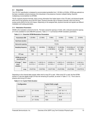
![12 Overview of the 3GPP Long Term Evolution Physical Layer Freescale Semiconductor
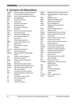
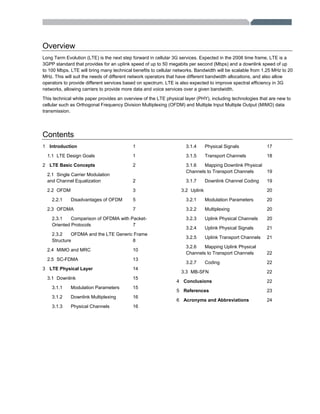
Figure 2.4-3 Reference Signals Transmitted Sequentially to Compute Channel Responses for
MIMO Operation
R0
R0
R0
R0
R0
R0
R0
R0
R1
R1
R1
R1
R1
R1
R1
R1
Denotes Unused
Resource Element
R0
Reference Signal
from Antenna 0
R1
Reference Signal
from Antenna 1
Antenna 0 Antenna 1
Subcarriers
(frequency)
OFDM Symbols
(time)
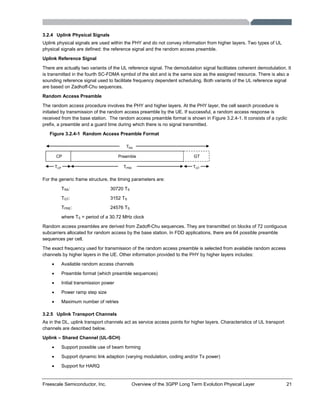
In order to successfully receive a MIMO transmission, the receiver must determine the channel impulse response from
each transmitting antenna. In LTE, channel impulse responses are determined by sequentially transmitting known
reference signals from each transmitting antenna as shown in Figure 2.4-3.
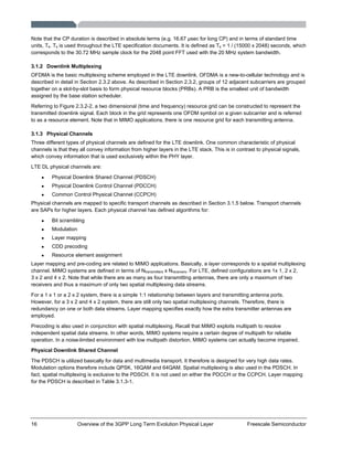
Figure 2.4-4 MIMO Operation Requires A Priori Knowledge of all Channel Responses
XCVR-A
Baseband
XCVR-B
XCVR-C
Baseband
XCVR-D
ChAC
ChAD
SC = REFA x ChAC
XCVR-A
Baseband
XCVR-B
XCVR-C
Baseband
XCVR-D
ChBC
SD = REFA x ChAD
ChBD
SC = REFB x ChBC
SD = REFB x ChBD
XCVR-A
Baseband
XCVR-B
XCVR-C
Baseband
XCVR-D
SC = [DATAA x ChAC] + [DATAB x ChBC]
SD = [DATAA x ChAD] + [DATAB x ChBD]
Reference Signal Transmitted from Antenna A
Reference Signal Transmitted from Antenna B
Data Transmitted Simultaneously from BOTH Antennas
Referring to the 2 x 2 MIMO system in Figure 2.4-4, there are a total of four channel impulse responses (C1, C2, C3 and
C4). Note that while one transmitter antenna is sending the reference signal, the other antenna is idle. Once the channel](https://image.slidesharecdn.com/3gppevolutionwp-101025033115-phpapp02/85/3-gppevolutionwp-14-320.jpg)
![14 Overview of the 3GPP Long Term Evolution Physical Layer Freescale Semiconductor
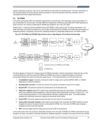
systems (removal of CP, conversion to the frequency domain, then apply the channel correction on a subcarrier-by-
subcarrier basis).
Unlike OFDM, the underlying SC-FDMA signal represented by the discrete subcarriers is—not surprisingly—single
carrier. This is distinctly different than OFDM because the SC-FDMA subcarriers are not independently modulated. As a
result, PAPR is lower than for OFDM transmissions. Analysis has shown that the LTE UE RFPA can be operated about
2 dB closer to the 1-dB compression point than would otherwise be possible if OFDM were employed on the uplink [2].
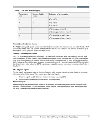
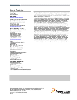
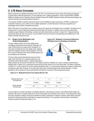
2.5-2 SC-FDMA Subcarriers Can be Mapped in Either Localized or Distributed Mode
Localized Subcarriers
freq freq
Distributed Subcarriers
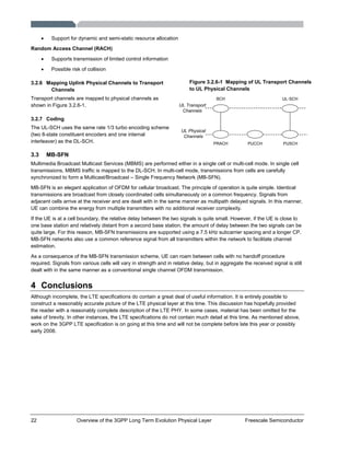
As mentioned above, SC-FDMA subcarriers can be mapped in one of two ways: localized or distributed as shown in
Figure 2.5-2. However, the current working assumption is that LTE will use localized subcarrier mapping. This decision
was motivated by the fact that with localized mapping, it is possible to exploit frequency selective gain via channel-
dependent scheduling (assigning uplink frequencies to UE based on favorable propagation conditions).
3 LTE Physical Layer
The capabilities of the eNodeB and UE are obviously quite different. Not surprisingly, the LTE PHY DL and UL are quite
different. The DL and UL are treated separately within the specification documents. Therefore, the DL and UL are
described separately in the following sections.
3.0.1 Generic Frame Structure
One element shared by the LTE DL and UL is the generic frame structure. As mentioned previously, the LTE
specifications define both FDD and TDD modes of operation. This paper deals exclusively with describing FDD
specifications. The generic frame structure applies to both the DL and UL for FDD operation. It is described in detail
Section 2.3.2 above, and the main points are repeated in this section.
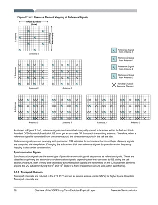
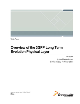
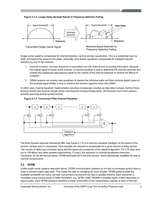
Figure 3.0.1-1 LTE Generic Frame Structure
0 1 2 3 10 11 19
1 Sub-Frame (1.0 msec)
1 Frame (10 msec)
50 1 2 3 4 6 50 1 2 3 4 6
7 OFDM Symbols
(short cyclic prefix)
cyclic prefixes
1 Slot (0.5 msec)
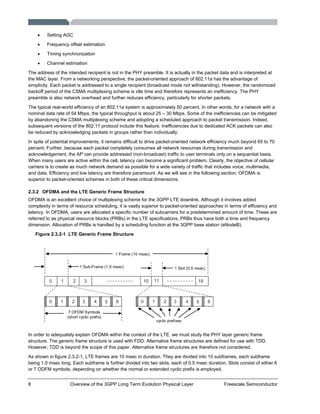
As described in Section 2.3.2, LTE transmissions are segmented into frames, which are 10 msec in duration. Frames
consist of 20 slot periods of 0.5 msec. Sub-frames contain two slot periods and are 1.0 msec in duration.](https://image.slidesharecdn.com/3gppevolutionwp-101025033115-phpapp02/85/3-gppevolutionwp-16-320.jpg)