This document summarizes research on harmonic voltage distortions in power systems due to non-linear loads. It describes how non-linear loads can generate harmonics and discusses their effects. It also examines harmonic reduction methods like passive filters. The research uses MiPower software to model a sample IEEE 5-bus power system and analyze harmonic distortions with and without filters. Installation of single and dual passive filters at different buses is shown to significantly reduce total harmonic distortion throughout the system. The document concludes that accurate harmonic analysis of power systems can be achieved using such simulation tools.
![International Journal of Applied Power Engineering (IJAPE)
Vol. 3, No. 1, April 2014, pp. 67~74
ISSN: 2252-8792 67
Journal homepage: http://iaesjournal.com/online/index.php/IJAPE
Harmonic Voltage Distortions in Power Systems due to Non
Linear Loads
Aryan Kaushik, Jyothi Varanasi
Departement of Electrical, Electronics and Communication Engineering, ITM University
Article Info ABSTRACT
Article history:
Received Feb 12, 2014
Revised Mar 21, 2014
Accepted Apr 1, 2014
Harmonics are found to have deleterious effects on power system equipments
including transformers, capacitor banks, rotating machines, switchgears and
protective relays. Transformers, motors and switchgears may experience
increased losses and excessive heating. Shunt filters are effective in
minimizing voltage distortions. This paper describes the voltage distortions
generated by non linear loads. The harmonic specifications such as harmonic
factor, characteristic harmonic and non-characteristic harmonic are
considered while explaining the paper. ‘MiPower’ software is used to
compute the harmonic distortions in a sample power system. Accurate
harmonic models are established for a non linear load. To reduce the
harmonic voltages impressed upon specific parts of the sample power
system, passive filters are installed at two buses. With the implementation of
a passive filter at the bus with non linear load, the harmonics are greatly
reduced. For the specified power system, at all the buses the total harmonic
distortion has been evaluated.
Keyword:
‘MiPower’ software
IEEE 5-Bus power system
Total Harmonic Distortions
Graphical User Interface
Copyright © 2014 Institute of Advanced Engineering and Science.
All rights reserved.
Corresponding Author:
Aryan Kaushik,
Departement of Electrical, Electronics and Communication Engineering,
ITM University,
Sector- 23A, Gurgaon, Haryana, India.
Email: er.aryankaushik@gmail.com
1. INTRODUCTION
The ensuing increase of harmonic penetration into power systems has been the hit topic of research
for the researches dealing with the harmonic sources, harmonic power flow techniques, designing of filters to
reduce harmonics, causes and effects of harmonic interferences and harmonic measurement techniques. This
research paper uses a suitable way of studying and analyzing the IEEE 5-Bus power system using the
‘MiPower’ software. The voltage distortion, which defines the relationship between the total harmonic
voltage and the total fundamental voltage, and the current distortion, which defines the relationship between
the total harmonic current and the fundamental current, are the basic considerations while dealing with the
harmonic distortions in the power system. Total Influence Factor (TIF), Total Demand Distortions (TDD)
and Total Harmonic Distortions (THD) are the harmonic specifications which discuss the propagation of
harmonics to different parts of the system.
There are two criteria which are used to evaluate harmonic distortions, first is the limitation in the
harmonic current that a user can transmit into the utility system and second is the quality of the voltage that
the utility must furnish the user [1].A simpler approach is taken into account for designing the filters. There
are various harmonic power flow programs which have already been developed in this particular field of
research such as Harmflo [2],[3]. This power flow program uses Newton Raphson iterative technique along
with the accurate models for convertor loads and non linear resistors. One more versatile and powerful
program is marketed by Cyme International Inc. of St. Bruno, Quebec [4]. One more effective approach is
proposed to compensate for harmonics in power systems in [5]. Analyzing the THD for a particular power](https://image.slidesharecdn.com/1323-964-1-pb-201208061724/75/Harmonic-Voltage-Distortions-in-Power-Systems-Due-to-Non-Linear-Loads-1-2048.jpg)
![ ISSN: 2252-8792
IJAPE Vol. 3, No. 1, April 2014 : 67 – 74
68
system has become relatively more accurate, simpler and easier using the ‘MiPower’ software which
provides a more interactive routine for small electrical networks. By focusing on power system variations and
their effects, the standard specifications are met accordingly.
2. SYSTEM FILTERING METHODS
As a method, system filters, whether active or passive, have the advantage of being retro-fit but the
disadvantage of being possibly only a temporary solution. If the power system changes, for example, if more
non linear load is added, the design assumptions will also change.
2.1 Passive Filters
Passive filters can be designed to reduce harmonic voltages and notch effects at particular points in
the power system. Each installation is different and the size and placement of the filters varies accordingly.
Usually, the passive filters include different types of parallel paths that present relatively low impedance to
the various harmonics. Harmonic currents flow into this reduced impedance such that the harmonic voltage at
that point is reduced. In some cases, there will be sufficient source impedance at the location at which
harmonics must be reduced that a single filter at that location can absorb harmonics from the multiple
harmonic sources. This point might be the point of common connection, but in any event, the filter must be
designed so as not to be overloaded by harmonic currents from other parts of the power system.
These filters are much more difficult to use in conjunction with auxiliary generators for two reasons.
Firstly, the generators cannot normally support more than about 20% leading KVAR because armature
reaction may cause over-excitation and voltage regulator instability. Secondly, frequency variations expected
with an auxiliary generator are much greater than those of the utility; therefore, the filter design is
complicated. Passive filters are widely used in conjunction with utility-type static VAR compensators and ac
electric arc furnaces with megawatt ratings [6]. In this type of application, the major source of harmonic
disturbance is well known, and the probability of system changes affecting the filter performance is small.
2.2 Add-On Active Filters
In this method, an additional power electronic convertor is used to supply the power source line with
the harmonic currents required by the non linear load. In essence, the filter is a power amplifier and must
have adequate bandwidth to compensate for the harmonic currents required by the electronic equipment, at
least up to the 25th
harmonic. Technically, this method is undoubtedly very effective. The main drawback lies
in its cost, which, with development, is expected to be comparable to an inverter of similar rating. In contrast
with typical motor drive inverters, which operate from a stable dc link voltage, the active filter is exposed to
voltage stresses caused by normal and fault conditions in the power system. This puts additional demands
upon the semiconductor switching devices, hybrid arrangements of active and passive components are also
feasible [7]. The supply voltage imbalance from the load terminal voltage is eliminated by a series-active
filter which also forces an existing shunt-passive filter to absorb all the current harmonics produced by a non
linear load [8].
3. ‘MiPower’ SOFTWARE
MiPower is the state-of-the-art windows based power systems software. It is highly interactive and
user friendly software for all analysis, planning, design and simulation of any given power system
irrespective of the geographical and environmental constraints. It is widely used by power utilities, academic
& research institutes for more than a decade. It is armed with robust power system engine in the backend and
a lucid top-notch Windows Graphical User Interface (GUI) in the front end. Approach, technique &
methodology employed are field proven & time tested. This conforms to standard ANSI, IEEE, IEC and
other world-wide accepted standards. All power system data is centrally maintained with an industry standard
relational database. It helps in dealing with a wide range of power system problems. Highly intuitive GUI
makes the learning curve smooth to a great extent. With the use of ‘MiPower’ software, power system
engineers can become productive with minimum effort and time and results are emphatically visible.
Figure 1. Single line diagram](https://image.slidesharecdn.com/1323-964-1-pb-201208061724/75/Harmonic-Voltage-Distortions-in-Power-Systems-Due-to-Non-Linear-Loads-2-2048.jpg)
![IJAPE ISSN: 2252-8792
Harmonic Voltage Distortions in Power Systems due to Non Linear Loads (Aryan Kaushik)
69
The single line diagram describes the very basic concept of a power system, which can be analyzed
using the ‘MiPower’ software. Figure 1 represents the single line diagram.
4. FILTER DESIGN
The filters are used to reduce the harmonic voltage and current components in the power system.
This research paper makes use of passive filters while computing THD for a non linear load to be simulated.
By providing a low impedance path for the injected harmonic currents at the point of injection, the harmonic
current and voltage components can be prevented from entering the network. Generally, tuned filters are
designed for the lower harmonics and damped filters are designed for the higher harmonics. The procedure of
designing these filters is given below without any degradation in performance. The conventional design of
tuned filters at a harmonic generating load bus involves the computation of the admittance locus for the
network as seen by the load bus [9]. This rather tedious step is avoided by taking into account the network
admittance for the tuning frequency only. The tuned filters consist of a series R-L-C circuit as shown in
Figure 2 (a). The impedance of this filter is capacitive at low frequencies and inductive at high frequencies.
(a)
(b)
Figure 2. (a) Tuned filter, (b) Second order damped filter
In addition to the tuned filters for lower harmonics, a filter which attenuates all the higher harmonics
called the damped filter is often employed. There are several types of damped filters, but the second order
damped filter is most widely used, which is shown in Figure 2 (b).
5. CASE STUDIES
The below described case studies explore the details of the power system used in this research paper
and on that basis, various operating conditions are being considered for the same power system.
5.1. System Description
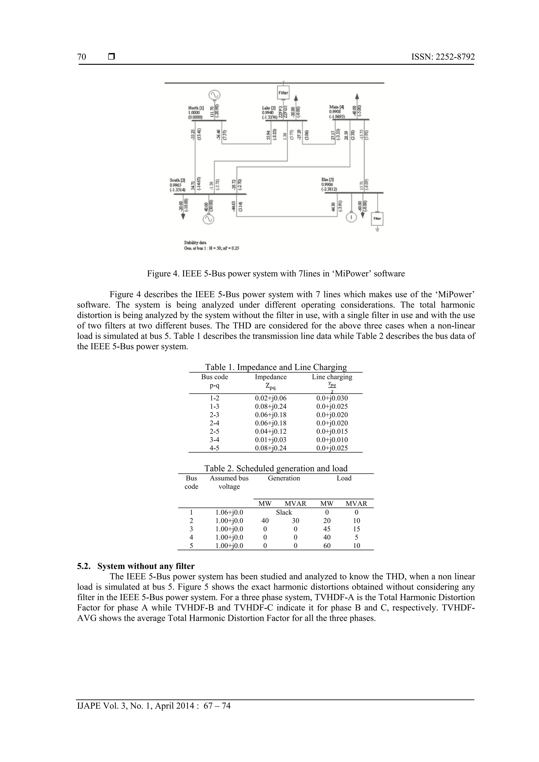
Figure 3. Generalized layout of IEEE 5-Bus power system with 7 lines
Figure 3 displays the generalized layout of the IEEE 5-Bus power system with 7 lines. Considering
this particular layout, helps in designing the same power system in ‘MiPower’ software.](https://image.slidesharecdn.com/1323-964-1-pb-201208061724/75/Harmonic-Voltage-Distortions-in-Power-Systems-Due-to-Non-Linear-Loads-3-2048.jpg)
![ ISSN: 2252-8792
IJAPE Vol. 3, No. 1, April 2014 : 67 – 74
72
5.5. Non linear loads and Harmonics
In AC power distribution systems, harmonics occur when the normal electric current waveform is
distorted by non linear loads. A linear load is one where voltage (a sine wave) is applied across a constant
resistance resulting in current (another sine wave), as shown in Figure 8. Non linear loads occur when the
resistance is not a constant and changes during each sine wave of the applied voltage waveform, resulting in
a series of positive and negative pulses, illustrated in Figure 9.
Figure 8. Linear load sine wave
Figure 9. Non linear current load pulses
Sources of non linear loads are computer equipments with switched-mode power supplies, variable
speed motors and drives, photocopiers, laser printers, fax machines, battery chargers, UPSs, fluorescent light
ballasts, and medical diagnostic equipment. Historically, single phase non linear loads were common in
office buildings and three phase non linear loads were generally found in factories and industrial plants.
However, data centers are increasingly moving to three phase power distribution.
5.6. Applications related to converters
Above discussed power system encompasses its essence to the harmonics occurring for non linear
loads, but there exists several power systems which consider the applications related to the converters. In the
industrial environment, Electronic power converters have become one of the major sources of harmonics
[10]. Some of the widely preferred converters are as follows:
1) Six-Pulse Converter with Capacitor-Input Filter which takes into account total source reactance, capacitor-
input filter and VFD inverter load.
2) Six-Pulse Converter with Inductor-Input Filter which takes into account total source reactance, inductor-
input filter and VFD inverter load.
5.6.1. Six-pulse converter with capacitor-input filter
Figure 10 displays the line current for a typical six-pulse converter with capacitor-input filter. This
type of filtering, in conjunction with ac line reactance, has been used up to 150 horse power rating but finds
greater application in the lower horse power ratings.
Figure 10. Six-pulse converter with capacitor-input filter
Linear load
Non linear load](https://image.slidesharecdn.com/1323-964-1-pb-201208061724/75/Harmonic-Voltage-Distortions-in-Power-Systems-Due-to-Non-Linear-Loads-6-2048.jpg)
![IJAPE ISSN: 2252-8792
Harmonic Voltage Distortions in Power Systems due to Non Linear Loads (Aryan Kaushik)
73
5.6.2. Six-pulse converter with inductor- input filter
Figure 11 displays the line current for a typical six-pulse converter with inductor-input filter.
Figure 11. Six-pulse converter with inductor-input filter
6. CONCLUSION
The observations and conclusions derived from the results obtained through simulation studies are
listed below:
6.1. Harmonic analysis
For the IEEE 5-Bus power system is considered in this paper, this harmonic analysis program is
found to be extremely fast. The effective use of the software is being made which draws several conclusions
related to the harmonic distortions in the particular power system operating under different conditions.
6.2. Case studies using filter design
This section describes the conclusions drawn from the IEEE 5-Bus power system to be considered
in various simulated conditions.
6.2.1. System without any filter
In the first case study, where the system is considered without making use of any filter, the THD for
the voltages are shown at all the buses. The distortion is observed as maximum at bus 5 as the non linear load
has been simulated at that bus. The maximum value observed comes as 23.83 (Distortion %).
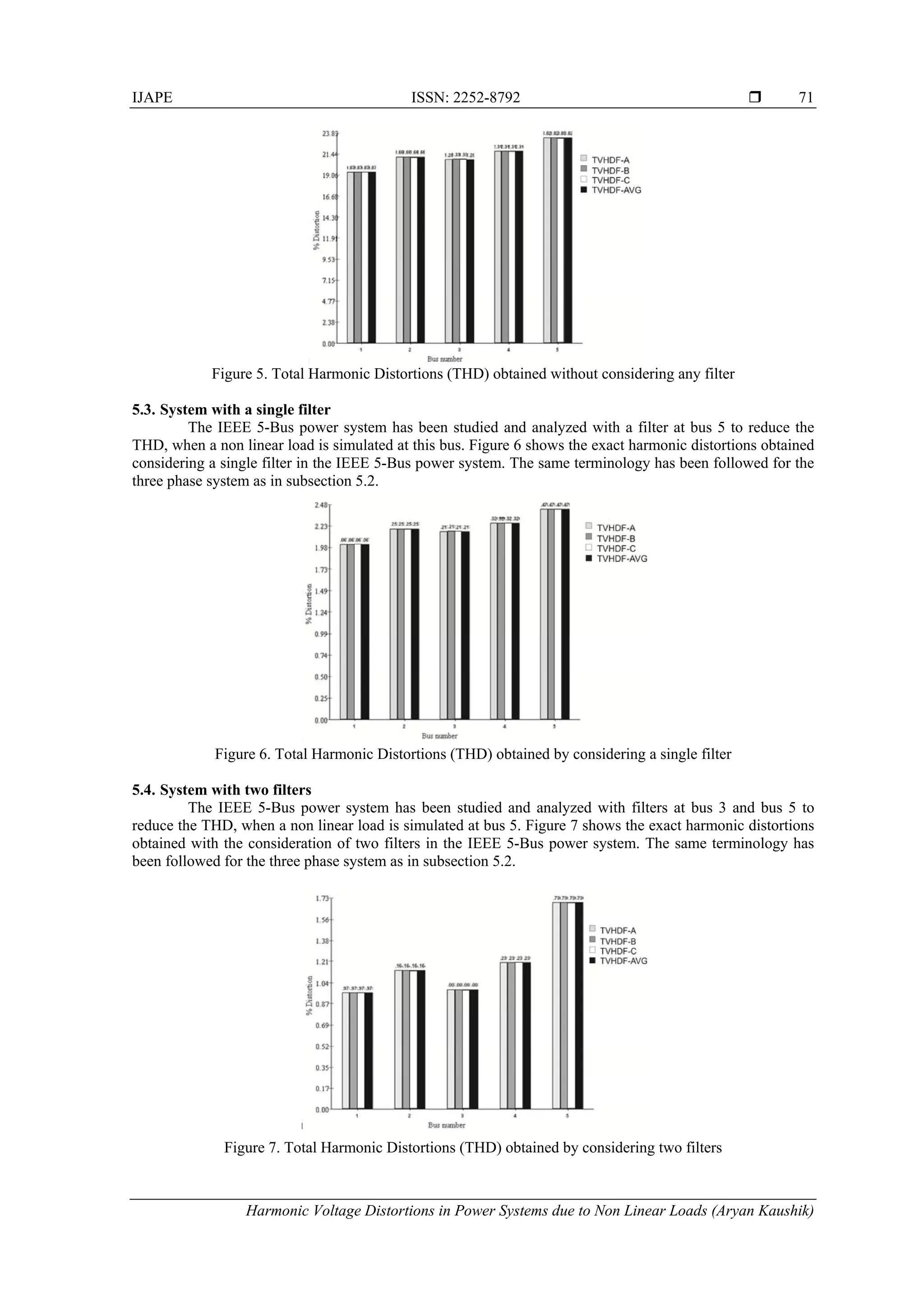
6.2.2. System with a single filter
In the second case study, where the system is considered with a single filter at bus 5, the THD for
the voltages are shown at all the buses. The distortions get reduced to a reasonable extent comparatively to
the system considered without any filter. The distortion is observed as maximum at bus 5 as the non linear
load has been simulated at that bus. The maximum value comes out to be 2.48 (Distortion %).
6.2.3. System with two filters
While carrying out the third case study, where the system is considered with two filters at bus 3 and
bus 5, the THD for the voltages are shown at all the buses. The distortions further get reduced comparatively
to the system considered with a single filter. The distortion is observed as maximum at bus 5 as the non linear
load has been simulated at that bus. The maximum value comes out to be 1.7 (Distortion %).
6.3. Advancement in the model
The applications of this particular model can be extended to the power systems with much larger
number of buses. The voltage distortions can be efficiently and simply analyzed using the ‘MiPower’
software. The same cases can be observed considering the system either without any filter or with a finite
number of filters.
REFERENCES
[1] C.K. Duffey and R.P. Stratford. "Update of Harmonic Standard IEEE-519", IEEE Recommended Practices and
Requirements for Harmonic Control in Electrical Power Systems, Paper No. PCIC-88-7. Pp. 1618-1624, 1989.
[2] G.T. Heydt, W.M. Grady and D. Xia. "Harmonic Power Flow Studies", Theoretical Basis, EPRI EL-3300, project
1764-7, Electric Power Research Institute, Palo Alto, CA, Vol. 1, 1983.
[3] G.T. Heydt, W.M. Grady and D. Xia. "Harmonic Power Flow Studies", Users' Guide, EPRI EL-3300-CCM, project
1764-7, Electric Power Research Institute, Palo Alto, CA, Vol. 2, 1983.
[4] Cyhharmog. Harmonic Analysis by Cyme International Inc., 1485 Roberval, Suite 204, St. Bruno, Quebec, Canada.](https://image.slidesharecdn.com/1323-964-1-pb-201208061724/75/Harmonic-Voltage-Distortions-in-Power-Systems-Due-to-Non-Linear-Loads-7-2048.jpg)
![ ISSN: 2252-8792
IJAPE Vol. 3, No. 1, April 2014 : 67 – 74
74
[5] Fang Zheng Peng, Hirofumi Akagi and Akira Nabae. "A New Approach to Harmonic Compensation in Power
Systems- A Combined System of Shunt Passive and Series Active Filters", IEEE Transactions on Industry
Applications, Vol/Issue: 26(6), 1990.
[6] L. Gyugyi and R.A. Otto. "Static VAR Compensation of Electric Arc Furnaces," presented at the VIE meeting,
Liege, Belgium, 1976.
[7] D. Divan, B. Banerjee, D. Pillegi, R. Zavadil and D. Atwood. "Design of an active series/passive parallel harmonic
filter for ASD loads at a waste-water treatment plant", Proceedings of Second International Conference on Power
Quality, sponsored by Electric Power Research Institute, Atlanta, September 28-30, 1992.
[8] Hideaki Fujita and Hirofumi Akagi. "The Unified Quality Conditioner: The Integration of Series- and Shunt-Active
Filters", IEEE Transactions on Power Electronics, Vol/Issue: 13(2), 1998.
[9] E.W. Kimbark. Direct Current Transmission, Vol.1, John Wiley and Sons, Inc. New York, 1971.
[10] Damian A. Gonzalez and John C. Mccall. "Design of Filters to Reduce Harmonic Distortion in Industrial Power
Systems", IEEE Transactions on Industry Applications, Vol/Issue: IA-23(3), 1987.
BIOGRAPHIES OF AUTHORS
Aryan Kaushik is with the Department of Electrical and Electronics Engineering, ITM
University, Gurgaon, Haryana, India (E-mail: er.aryankaushik@gmail.com)
Jyothi Varanasi is with the Department of Electrical and Electronics Engineering, ITM
University, Gurgaon, Haryana, India (E-mail: jyotivaranasi@itmindia.edu)](https://image.slidesharecdn.com/1323-964-1-pb-201208061724/75/Harmonic-Voltage-Distortions-in-Power-Systems-Due-to-Non-Linear-Loads-8-2048.jpg)