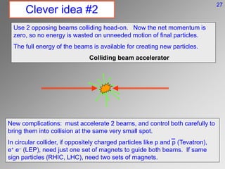
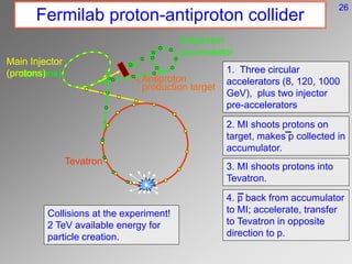
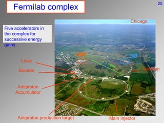
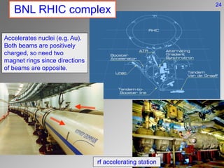
Particle Accelerators
Herding and Hurrying Cats
LI American Nuclear Society
June 19, 2008
Paul Grannis
What is an accelerator?
An accelerator is a device to produce beams of charged particles and
accelerate them to high velocity or energy (much greater than that for
electrons or nuclei in atoms) with:
 Nearly constant velocity or energy
 Parallel trajectories
 Small beam cross section
and to deliver these particles to a target where they scatter from the
target constituents and:
 Reveal the structure of the constituents (a microscope)
 Create new particles for study
 Modify the character of the target (e.g. a tumor)
source vacuum tube with force stations target
39
Why build accelerators?
In the 1930’s, physicists wanted to understand the
structure of the atomic nucleus, and the strong force
that binds it together. Naturally occurring radioactive
decays give particles of energies of a few MeV; need
to produce particles of higher energy.
In 1931, E.O. Lawrence made the first modern
particle accelerator – the cyclotron – with successive
versions reaching over 100 MeV.
The need for higher energy is two-fold:
1. Creation of new nuclei/particles of higher mass than the natural
elements requires energy : E = mc2. Nowadays we seek new states of
matter at the millions of MeV level. Today’s accelerators deliver
beams of ~10 TeV.
2. In analogy with the microscope, seeing finer detail within subatomic
particles requires a wavelength l smaller than the size of the object.
deBroglie told us that l = h/p, and the momentum p ~ E. Modern
accelerators probe structure at the 10-19 m level.
1 eV = energy gained
by electron by 1 V
battery.
1 keV = 1000 eV
1 MeV = 106 eV
1 GeV = 109 eV
1 TeV = 1012 eV
electron binding in
atoms ≈ 1 eV
proton binding in
nuclei ≈ 1 MeV
proton mass energy
≈1 GeV
38
What can we accelerate?
All accelerators are based on acceleration of charged particles by
electric forces.
We accelerate elementary particles and nuclei which have small mass
(F = ma, so a = F/m) to get beams of high velocity (and energy).
Bringing a charged particle from nearly at rest to high energy requires
that it be sufficiently stable to not decay in flight.
The particles must exist in sufficient abundance to give high intensity
beams (the collision processes are rare).
 This limits the available particles to electrons and positrons,
protons, nuclei (atoms stripped of their electrons) and antiprotons
(though making them in abundance is hard). Maybe in future can
use muons (but they decay in a microsecond!).
Electric field E
proton of charge q
Force F = q E
37
M87 – giant elliptical
long exposure
short exposure shows a
jet emerging from galaxy
Magnified jet
viewed in radio
Magnified jet
viewed in IR
Nature’s accelerators
Several views of the M87
galaxy in the Virgo cluster
As usual, Nature is more clever than we are: many galaxies show ‘jets’ of
light, X-rays resulting from electrons accelerated to high velocity by the
spinning black hole at their center. The light results from radiation by the
electrons curling around very strong magnetic fields.
But assembling a
supermassive black
hole on earth is not
recommended.
36
How to accelerate?
We surf the
wave!
35
v
Ez
z
How to accelerate?
Make the rf wave travel at the speed of
the particles, so get a continuous push.
Synchronize the particle bunches just
ahead of the peak of the wave. Thus a
particle that is a little too low in velocity
falls behind where E is larger, and so
gets a larger push to catch up with the
bunch.
The rf wave is confined in a set of
‘cavities’ whose shape controls
the speed of the wave.
Energy gain = force x distance = q E l
Energy gain/meter of 30 – 100 MeV/m is
possible using rf cavities.
Provide the accelerating electric field as
travelling radio frequency (rf) wave (higher
E than static fields). Input particles in
bunches that ‘surf the wave’, gaining
energy due to the electric force.
34
How to contain the beams?
The particles tend to stray from the
straight and narrow. Any deviation of
particle direction from the desired axis
would lead to beam blow-up.
Such divergence occurs due to the
particle source, mutual repulsion of
beam particles, imperfections in the
accelerator, etc.
We need a way to restore directions
to the desired axis.
33
How to contain the beams?
Strong focusing principle:
Quadrupole magnets focus the beams, similar to
lenses in ordinary optics (4 poles rather than 2 for
dipole) and magnetic field pattern as shown.
Field grows linearly with distance from center.
Particle is deflected toward center. Particle is
deflected away from center. So focus horizontally
and defocus vertically (and vice versa).
Ray hits the horizontal focusing
element further out and bends
more than at the defocussing
element. So get net focussing
effect. Same in vertical plane.
horizontal
plane
vertical
plane
Q1 Q2
Beam coming out of
screen
Alternate F and D elements to
oscillate the particles around
the beam axis (betatron
oscillations).
32
Betatron oscillations
Individual particles oscillate around
their central orbit, but stay confined.
31
Clever idea #1
Conserve real estate and save on components by bending the beams into
a circular path so that they repeatedly traverse the same rf accelerating
cavities and quadrupoles. Do this by passing the beams through bending
magnets.
The AGS at
Brookhaven Lab
Magnetic
field
F = ma  qvB = mv2/R or E(GeV) = 0.3 B(T) x R(m)
F
R
The world’s most powerful accelerator – LHC at CERN, starting this year –
has average magnetic field of 5.5T (8.3T in the magnets), and will
accelerate protons to 7 TeV (7000 GeV). Thus R = 4.3 km.
If we wanted 100 TeV, would need a circular ring 125 km in diameter!
30
(at large velocities ≈ c)
Limits on circular accelerators
When charged particles are accelerated, they radiate EM waves (for example
acceleration in radio antennas creates the radio signal). Charges going in a
circle are accelerated (centripetal), so they emit synchrotron radiation.
Energy radiated per turn ~ E4/(R m4) (E = beam energy, m=particle
mass)
Lessons: power radiated grows very rapidly with beam energy. Making the
circle larger helps but not very fast. And the radiation for electron
accelerators is very much more than for protons (mp/me = 2000).
For the LEP electron accelerator at CERN (100 GeV electron beams with R
= 4.3 km) an electron loses 4% of its energy every time around the circle,
and requires 20 MW of rf power just to break even. This is about the end of
the road for circular electron accelerators, so must consider linear
accelerators.
Radiation is along particle direction, like a
searchlight – X-rays, UV and visible light.
Used to study biological processes and
materials in ‘light sources’.
29
Old way of using beams
Accelerate protons in Tevatron to 100’s of GeV
Extract protons from Tevatron and send to a target.
A spray of many particles of all types are produced
in the collisions in the target – p mesons, K mesons,
photons, protons, neutrons etc.
Select and focus one stream of secondary particles
and send to the experiment.
Tevatron
Target station Experiment
In the collision of beam and target particles, we must
conserve momentum so produced particles must move to
right, limiting the energy available to produce new particles.
28
Clever idea #2
Use 2 opposing beams colliding head-on. Now the net momentum is
zero, so no energy is wasted on unneeded motion of final particles.
The full energy of the beams is available for creating new particles.
Colliding beam accelerator
New complications: must accelerate 2 beams, and control both carefully to
bring them into collision at the same very small spot.
In circular collider, if oppositely charged particles like p and p (Tevatron),
e+ e- (LEP), need just one set of magnets to guide both beams. If same
sign particles (RHIC, LHC), need two sets of magnets.
27
Fermilab proton-antiproton collider
Antiproton
production target
Main Injector
(antiprotons)
Antiproton
accumulator
Main Injector
(protons)
Tevatron
1. Three circular
accelerators (8, 120, 1000
GeV), plus two injector
pre-accelerators
2. MI shoots protons on
target, makes p collected in
accumulator.
3. MI shoots protons into
Tevatron.
4. p back from accumulator
to MI; accelerate, transfer
to Tevatron in opposite
direction to p.
Collisions at the experiment!
2 TeV available energy for
particle creation.
26
Linac
Booster
Antiproton
Accumulator
Main Injector
Antiproton production target
Tevatron
DØ
CDF
Chicago
Fermilab complex
Five accelerators in
the complex for
successive energy
gains.
25
BNL RHIC complex
rf accelerating station
Accelerates nuclei (e.g. Au).
Both beams are positively
charged, so need two
magnet rings since directions
of beams are opposite.
24
Stanford Linear Accelerator Center
3 mile long linac, accelerating electrons or positrons to 50 GeV, used for
fundamental studies of quarks until 2008. Now being converted to a
free electron laser light source.
The Linac crosses
above the foothills near
San Francisco Bay,
across the San Andreas
fault and I-280.
23
CERN and the Large Hadron Collider
The 5.5 mile diameter underground tunnel originally housed the e+e- collider
LEP. It is now being readied for 14 TeV proton-proton collisions at the LHC.
Mt. Blanc
Lake Geneva
City of Geneva
Airport
LHC
Tunnel housing LHC is ~100m
underground. The energy stored
in the beams is equivalent to an
aircraft carrier moving at 12 knots,
enough to melt 1 ton of Cu (be
careful where the beam goes!!)
(LHC will not make black holes
that swallow the earth!)
22
International Linear Collider
We strongly believe that the LHC will discover new phenomen. To
explain those new discoveries, we will need a complementary
electron-positron collider operating at 500 – 1000 TeV. The ILC is
being designed to do that job.
Two opposing linear (to eliminate synchrotron radiation) accelerators (e- & e+)
of about 10 km length each, bringing beams to a collision spot about 6 nm
high by 100 nm wide. Initially each linac has E=250 GeV, upgradable to 500
GeV (1 TeV collisions).
21
main linac
bunch
compressor
damping
ring
source
pre-accelerator
collimation
final focus
IP
extraction
& dump
KeV
few GeV
few GeV
few GeV
250-500 GeV
Layout of electron arm
ILC systems
Show one-half of ILC – the electron linac. Positron side is nearly identical.
1. Source provides the
polarized electrons
2. Pre-acceleration linac to
5 GeV
3. Damping ring to make the
beam cross section very
small
4. Bunch compressor squeeze
bunch along beam direction
5. Main linac to accelerate to
full energy
6. Bring beams to collision and
remove them safely to dump
20
ILC Sources
Electron source: Shine a laser (polarized light) on GaAs crystal and eject
polarized electrons. Pre-accelerate to 5 GeV.
Positron source: Pass the accelerated electron beam through a magnet that
wiggles the electrons in a helix, emitting polarized photons (synchrotron
radiation). Let the photons strike a target creating positrons (and electrons).
Send the polarized positrons to their damping ring and linac. Original
electrons continue down their original path in the linac.
150 GeV
electron beam
helical wiggler
magnet
radiated polarized
photons
conversion
target
produced
e- sent to
dump
polarized e+
sent to
positron linac
magnet
high energy
electrons
continue in
their linac
19
ILC Damping Rings
Damping rings function is to reduce the size of the beam (in transverse
positions and velocities). Bend the beams, emitting synchrotron radiation and
reducing all components of momentum. Then boost just the momentum along
the beam direction. Fractional transverse momenta are lowered.
3 initial particle rays with
finite divergence
magnet bend
radiated photons
carry off energy
reduced energy particles
with same divergence rf accel; increase
longitudinal momentum
final rays back to original
energy but smaller
divergence
Test damping ring in Japan has
achieved the small beam size
required for ILC.
R&D needed to control buildup of
electrons in rings that destroy the
small size.
18
Main Linacs (heart of ILC)
Ultra-pure Nb superconducting
cavities made from 9 clam shells
welded together. Inject rf wave to
provide 35 MeV gain in 1 meter.
Require cavities with 35 MV/m
and low loss (high Q). Some
have reached this specification.
But reliably preparing the very
smooth surfaces needed is still a
problem.
chemica
l etch
electro-
polish
ILC specs
17
Generating the rf electric field
Need 800 of these (they last
for about 50,000 hours.
Klystron tube : convert pulse
to 10 MW rf wave at 1.3 MHz.
Modulator :
convert AC power
from grid to 120 kV,
140 A pulses, 1 msec
long.
26 cavities (1 quadrupole focus magnet) in
three cryomodules, all fed by 1 klystron.
16
Beam particles induce
electromagnetic fields and currents in
the walls of the enclosure:
“wakefields”. If the beam is exactly
on central axis, these fields cancel at
the beam location.
If not, they create an net force on the
beam that tries to blow it up.
Wakefield from head of bunch gives extra
kick to tail of bunch, skewing the beam.
15
Herding the cats
bunch
0 km 5 km 10 km
head
head
head
tail
tail
tail
accelerator axis
cavities
Dy
tail performs
oscillation
equal
electric force
unequal force
Herding the cats –
need some negative
feedback
Controlling the wakefields:
1. Align the beam cavities, magnets very accurately (micron level) – won’t
work completely due to ground motion and environmental noise.
2. So need very sensitive detectors to measure the beam positions and give
feedback to reposition the beams on the proper axis (on 1 sec level).
3. Wakefield mitigation by making the tail of the beam a little lower in
energy so the quadrupole focussing restores the tail more than the head.
Dtb
Wakefields can also affect
subsequent bunches of
particles; control by making
the walls a bit resistive to
damp the currents before the
next beam bunch arrives. Beam quality (size) control is a tricky
business and gives much
14
Hopes for the future
Machines like LHC and ILC are pushing the limits of technology and
cost.
 Making magnets with > 10 Tesla fields is not presently possible. So
circular machines must grow as energy grows.
 Synchrotron energy grows rapidly as energy increases – ultimately a
limit for proton accelerators as well as electrons.
 Electron linacs like ILC are limited by the available accelerating
gradients in the cavities: We run into intrinsic materials breakdowns for
> 50 MV/m; so can increase energy only by making longer accelerator.
Increased size  cost (most of cost is related to civil construction, or
components that fill the accelerator length).
How might accelerators of the future evade today’s
limits?
13
Plasma accelerators (good
wakefields?)
R&D effort to develop plasma wakefield accelerators with accelerating
gradients ~1000 times that available with conventional RF cavities.
Plasma = A hot soup of electrons and ions, ordinary atoms dissociated by
heat or electricity. For accelerator use, create the plasma by intense lasers,
or electrical discharge, and contain the plasma within the beam tube.
Variant A: Send a conventional beam of electrons (or positive particles) into a
plasma. The beam expels the plasma electrons and causes periodic regions
of high and low electron density = plasma wakefield. Electrons ejected at
point A are attracted to the ion excess at B. The electron pattern is wavelike
and gives electric fields that accelerates the beam.
A
B
12
Plasma accelerators
+
+
+
+
+
+
+
+
+
+
+
+
+
+ +
+
+
+
+
+
+
+
+
+
+
+
+
+
+
+
--
-
-
- -
-
--
-
-
--
-
-
-
--
-
-
-
-
-
-
-
-
-
-
-
-
-
-
-
-
--
-
-
-
-
-
-
--
-
-
- -
-
--
-
-
--
-
-
-
-
-
-
--
-
-
-
-
-
-
-
--
-
- --
-
-
--
- --- -
-
-
-
-
-
-
-
--
- -
- ------ - -- -
-
-
-
-
- - -
- - - - -
-
- --
- -
- - - - - -
-
-
-
---
-
-
-
-
-
-
-
-
+ + + + + + + + + + +
+ + + + + + + + + + + + + + +
+ + + + + + + + + + + + + + +
+ + + + + + + + + + + + + + +
-
- -
-
-
-
- --
Ez
Plasma wakefield is standing wave that
can accelerate subsequent bunches of
particles.
Experiment at SLAC showed that some
42 GeV electrons (accelerated over 3
miles by conventional rf) were doubled in
energy in 84 cm of plasma!
But only a small fraction of beam is
accelerated. And beam size is rather
large. More R&D!
Beam energy 
42 GeV 84 GeV
11
Laser plasma accelerators
Variant B. Create a plasma in a thin
tubular channel using lasers. A
subsequent high power laser pulse is
confined to the tube, and its electric fields
accelerate plasma electrons from rest. (no
prior accelerator!) Earlier problems of
keeping the laser light focussed, and the
effect of light outrunning the particles have
been solved for 3 cm long acceleration
cells.
Group at Berkeley has succeed in
accelerating electrons from rest in
the plasma to 1 GeV in 3.3 cm.
30 GeV/m (1000xILC!)
The beam has small spatial and
energy spread, so R&D will now
focus on capturing the beam and
accelerating further in subsequent
cells.
10
1 GeV
Energy 
Diffusion into broader society
New ideas and tools invented for a particular scientific purpose have a
way of finding applications in broader contexts.
 Quantum mechanics, devised to explain the workings of the atoms,
led to transistors, computers, lasers …
 Studies of nuclear spin transitions led to MRI tomography
 Superconductivity led to high field magnets, train levitation, cryo-
treatments …
So it has been for particle
accelerators. The ability of
high energy particle beams to
probe small structures and
create new forms of matter now
find use elsewhere:
ACCELERATORS IN USE
WORLDWIDE
Particle/nuclear ~120
Synchroton light sources
~50
Medical radioisotopes ~200
Radiotherapy ~7500
Biomedical research ~1000
Industrial processing/R&D >1500
Ion implantation etc. >7000
9
Synchrotron light source
Experimental beam lines
Synchrotron radiation is used to
study protein structure, materials
properties, environmental effects,
chemical reactions, nanofabrication
and much more. Typically a few
GeV electron accelerator is used.
Electron
accelerator many beamlines
8
Much of the cutting edge research
in biology, solid state physics,
materials science, chemistry &
environmental science is done at
light sources around the world –
operating on principles established
in particle physics accelerators.
Accelerators for society
Most medical imaging for
diagnostics came from
accelerator technology:
 Computer assisted
tomography
 MRI
 PET scans
Accelerators are also used for:
 making nuclear isotopes for
diagnostics/treatment
 microlithography of electronic circuits
 ion implantation for electronics
 sterilizing foods
Possible future uses:
 Linac induced nuclear reactors – safe, clean, non-uranium fuels,
efficient
 Security – naval vessel protection, container scanning etc.
7
Metastasized
prostate cancer
seen in PET
scan
Most proton dose is deposited in the shar
"Bragg Peak", with no dose beyond
X-rays deposit most of their dose
near the surface (skin) of the
patient
Vary proton energy to
cover the tumor
Proton cancer treatment
Traditional X-ray radiation does not penetrate far, loses much of its
energy near the surface (burns), has broad spectrum of energy.
Protons from 50 – 200 MeV penetrate to any place in the body. They lose
little energy until the last few cm, so dose is concentrated on tumor.
Proton facilities are large and costly
– only two in the US. This is a
place where the plasma wakefield
acceleration R&D could pay off
handsomely by drastically reducing
the size and cost of the accelerator.
6
Commercial electron linac
for cancer treatment
Loma Linda (California)
- synchrotron source
- built/commissioned at Fermilab
- world leading patient throughput
Medical accelerators
~ 50 m
5
Proton beam induced nuclear
reactors
For some years, people have advanced the notion of high energy proton
initiation of nuclear reactors (Energy Amplifier). This idea is re-vitalized
with the advent of high power proton linacs based on the ILC SC
cavities.
Proton linac working at several
GeV, ~10 MW power creates
fast neutrons in the Th reactor
core. Th232 has 14x109 yrs half
life and 5x abundance of U238.
Th captures fast neutrons
(~100 keV); is a fertile
(breeder) nucleus; n + Th232 
Th233  (b) Pa233  (b) U233.
U233 fissions
10 MW p linac
Linac beam power of ~ 10 MW, consuming ~40 MW from grid Reactor
produces ~700 MW to the grid.
4
Proton beam induced nuclear
reactors
EA viability still debated by nuclear
community; much R&D still needed on
accelerator systems and system issues.
Breeder reactions are subcritical – k factor ~ 0.98
(safe).
Buildup of
isotopes in
operation.
Fission products are relatively short lived.
3
Who develops accelerator science?
Accelerator science is a very rich mixture of
disciplines
 Classical and quantum physics
 Applied mathematics
 Computer science
 Materials science
 Electrical engineering
 Mechanical and civil engineering
People have come from all of these fields.
There are no dedicated educational programs for accelerator science in US
universities. Some universities situated near major accelerators train
students from other disciplines (including Stony Brook) with supervisors from
Labs.
Stony Brook and Brookhaven Laboratory offer a nearly unique pairing of a
laboratory with world class facilities, and university with good students and
strong departments.
Scientists in both institutions are working to develop an Accelerator Science
But there aren’t
enough of them.
2
Conclusion
 Accelerators arising from needs in basic research have
increased in power by million-fold in 75 years, and have
revealed the microscopic world in great detail.
 Many wonderful new ideas enabled this growth, but we are
still limited by fundamental physical parameters – materials
breakdown, magnet strength etc. Current research on
plasma wakefield acceleration is promising.
 Accelerators have entered the mainstream of society,
particularly in medicine and electronics industry. Trend toward
miniaturization and cost reduction will only enhance this.
LIANS_accelerators.ppt

LIANS_accelerators.ppt

  • 1.
    Particle Accelerators Herding andHurrying Cats LI American Nuclear Society June 19, 2008 Paul Grannis
  • 2.
    What is anaccelerator? An accelerator is a device to produce beams of charged particles and accelerate them to high velocity or energy (much greater than that for electrons or nuclei in atoms) with:  Nearly constant velocity or energy  Parallel trajectories  Small beam cross section and to deliver these particles to a target where they scatter from the target constituents and:  Reveal the structure of the constituents (a microscope)  Create new particles for study  Modify the character of the target (e.g. a tumor) source vacuum tube with force stations target 39
  • 3.
    Why build accelerators? Inthe 1930’s, physicists wanted to understand the structure of the atomic nucleus, and the strong force that binds it together. Naturally occurring radioactive decays give particles of energies of a few MeV; need to produce particles of higher energy. In 1931, E.O. Lawrence made the first modern particle accelerator – the cyclotron – with successive versions reaching over 100 MeV. The need for higher energy is two-fold: 1. Creation of new nuclei/particles of higher mass than the natural elements requires energy : E = mc2. Nowadays we seek new states of matter at the millions of MeV level. Today’s accelerators deliver beams of ~10 TeV. 2. In analogy with the microscope, seeing finer detail within subatomic particles requires a wavelength l smaller than the size of the object. deBroglie told us that l = h/p, and the momentum p ~ E. Modern accelerators probe structure at the 10-19 m level. 1 eV = energy gained by electron by 1 V battery. 1 keV = 1000 eV 1 MeV = 106 eV 1 GeV = 109 eV 1 TeV = 1012 eV electron binding in atoms ≈ 1 eV proton binding in nuclei ≈ 1 MeV proton mass energy ≈1 GeV 38
  • 4.
    What can weaccelerate? All accelerators are based on acceleration of charged particles by electric forces. We accelerate elementary particles and nuclei which have small mass (F = ma, so a = F/m) to get beams of high velocity (and energy). Bringing a charged particle from nearly at rest to high energy requires that it be sufficiently stable to not decay in flight. The particles must exist in sufficient abundance to give high intensity beams (the collision processes are rare).  This limits the available particles to electrons and positrons, protons, nuclei (atoms stripped of their electrons) and antiprotons (though making them in abundance is hard). Maybe in future can use muons (but they decay in a microsecond!). Electric field E proton of charge q Force F = q E 37
  • 5.
    M87 – giantelliptical long exposure short exposure shows a jet emerging from galaxy Magnified jet viewed in radio Magnified jet viewed in IR Nature’s accelerators Several views of the M87 galaxy in the Virgo cluster As usual, Nature is more clever than we are: many galaxies show ‘jets’ of light, X-rays resulting from electrons accelerated to high velocity by the spinning black hole at their center. The light results from radiation by the electrons curling around very strong magnetic fields. But assembling a supermassive black hole on earth is not recommended. 36
  • 6.
    How to accelerate? Wesurf the wave! 35
  • 7.
    v Ez z How to accelerate? Makethe rf wave travel at the speed of the particles, so get a continuous push. Synchronize the particle bunches just ahead of the peak of the wave. Thus a particle that is a little too low in velocity falls behind where E is larger, and so gets a larger push to catch up with the bunch. The rf wave is confined in a set of ‘cavities’ whose shape controls the speed of the wave. Energy gain = force x distance = q E l Energy gain/meter of 30 – 100 MeV/m is possible using rf cavities. Provide the accelerating electric field as travelling radio frequency (rf) wave (higher E than static fields). Input particles in bunches that ‘surf the wave’, gaining energy due to the electric force. 34
  • 8.
    How to containthe beams? The particles tend to stray from the straight and narrow. Any deviation of particle direction from the desired axis would lead to beam blow-up. Such divergence occurs due to the particle source, mutual repulsion of beam particles, imperfections in the accelerator, etc. We need a way to restore directions to the desired axis. 33
  • 9.
    How to containthe beams? Strong focusing principle: Quadrupole magnets focus the beams, similar to lenses in ordinary optics (4 poles rather than 2 for dipole) and magnetic field pattern as shown. Field grows linearly with distance from center. Particle is deflected toward center. Particle is deflected away from center. So focus horizontally and defocus vertically (and vice versa). Ray hits the horizontal focusing element further out and bends more than at the defocussing element. So get net focussing effect. Same in vertical plane. horizontal plane vertical plane Q1 Q2 Beam coming out of screen Alternate F and D elements to oscillate the particles around the beam axis (betatron oscillations). 32
  • 10.
    Betatron oscillations Individual particlesoscillate around their central orbit, but stay confined. 31
  • 11.
    Clever idea #1 Conservereal estate and save on components by bending the beams into a circular path so that they repeatedly traverse the same rf accelerating cavities and quadrupoles. Do this by passing the beams through bending magnets. The AGS at Brookhaven Lab Magnetic field F = ma  qvB = mv2/R or E(GeV) = 0.3 B(T) x R(m) F R The world’s most powerful accelerator – LHC at CERN, starting this year – has average magnetic field of 5.5T (8.3T in the magnets), and will accelerate protons to 7 TeV (7000 GeV). Thus R = 4.3 km. If we wanted 100 TeV, would need a circular ring 125 km in diameter! 30 (at large velocities ≈ c)
  • 12.
    Limits on circularaccelerators When charged particles are accelerated, they radiate EM waves (for example acceleration in radio antennas creates the radio signal). Charges going in a circle are accelerated (centripetal), so they emit synchrotron radiation. Energy radiated per turn ~ E4/(R m4) (E = beam energy, m=particle mass) Lessons: power radiated grows very rapidly with beam energy. Making the circle larger helps but not very fast. And the radiation for electron accelerators is very much more than for protons (mp/me = 2000). For the LEP electron accelerator at CERN (100 GeV electron beams with R = 4.3 km) an electron loses 4% of its energy every time around the circle, and requires 20 MW of rf power just to break even. This is about the end of the road for circular electron accelerators, so must consider linear accelerators. Radiation is along particle direction, like a searchlight – X-rays, UV and visible light. Used to study biological processes and materials in ‘light sources’. 29
  • 13.
    Old way ofusing beams Accelerate protons in Tevatron to 100’s of GeV Extract protons from Tevatron and send to a target. A spray of many particles of all types are produced in the collisions in the target – p mesons, K mesons, photons, protons, neutrons etc. Select and focus one stream of secondary particles and send to the experiment. Tevatron Target station Experiment In the collision of beam and target particles, we must conserve momentum so produced particles must move to right, limiting the energy available to produce new particles. 28
  • 14.
    Clever idea #2 Use2 opposing beams colliding head-on. Now the net momentum is zero, so no energy is wasted on unneeded motion of final particles. The full energy of the beams is available for creating new particles. Colliding beam accelerator New complications: must accelerate 2 beams, and control both carefully to bring them into collision at the same very small spot. In circular collider, if oppositely charged particles like p and p (Tevatron), e+ e- (LEP), need just one set of magnets to guide both beams. If same sign particles (RHIC, LHC), need two sets of magnets. 27
  • 15.
    Fermilab proton-antiproton collider Antiproton productiontarget Main Injector (antiprotons) Antiproton accumulator Main Injector (protons) Tevatron 1. Three circular accelerators (8, 120, 1000 GeV), plus two injector pre-accelerators 2. MI shoots protons on target, makes p collected in accumulator. 3. MI shoots protons into Tevatron. 4. p back from accumulator to MI; accelerate, transfer to Tevatron in opposite direction to p. Collisions at the experiment! 2 TeV available energy for particle creation. 26
  • 16.
    Linac Booster Antiproton Accumulator Main Injector Antiproton productiontarget Tevatron DØ CDF Chicago Fermilab complex Five accelerators in the complex for successive energy gains. 25
  • 17.
    BNL RHIC complex rfaccelerating station Accelerates nuclei (e.g. Au). Both beams are positively charged, so need two magnet rings since directions of beams are opposite. 24
  • 18.
    Stanford Linear AcceleratorCenter 3 mile long linac, accelerating electrons or positrons to 50 GeV, used for fundamental studies of quarks until 2008. Now being converted to a free electron laser light source. The Linac crosses above the foothills near San Francisco Bay, across the San Andreas fault and I-280. 23
  • 19.
    CERN and theLarge Hadron Collider The 5.5 mile diameter underground tunnel originally housed the e+e- collider LEP. It is now being readied for 14 TeV proton-proton collisions at the LHC. Mt. Blanc Lake Geneva City of Geneva Airport LHC Tunnel housing LHC is ~100m underground. The energy stored in the beams is equivalent to an aircraft carrier moving at 12 knots, enough to melt 1 ton of Cu (be careful where the beam goes!!) (LHC will not make black holes that swallow the earth!) 22
  • 20.
    International Linear Collider Westrongly believe that the LHC will discover new phenomen. To explain those new discoveries, we will need a complementary electron-positron collider operating at 500 – 1000 TeV. The ILC is being designed to do that job. Two opposing linear (to eliminate synchrotron radiation) accelerators (e- & e+) of about 10 km length each, bringing beams to a collision spot about 6 nm high by 100 nm wide. Initially each linac has E=250 GeV, upgradable to 500 GeV (1 TeV collisions). 21
  • 21.
    main linac bunch compressor damping ring source pre-accelerator collimation final focus IP extraction &dump KeV few GeV few GeV few GeV 250-500 GeV Layout of electron arm ILC systems Show one-half of ILC – the electron linac. Positron side is nearly identical. 1. Source provides the polarized electrons 2. Pre-acceleration linac to 5 GeV 3. Damping ring to make the beam cross section very small 4. Bunch compressor squeeze bunch along beam direction 5. Main linac to accelerate to full energy 6. Bring beams to collision and remove them safely to dump 20
  • 22.
    ILC Sources Electron source:Shine a laser (polarized light) on GaAs crystal and eject polarized electrons. Pre-accelerate to 5 GeV. Positron source: Pass the accelerated electron beam through a magnet that wiggles the electrons in a helix, emitting polarized photons (synchrotron radiation). Let the photons strike a target creating positrons (and electrons). Send the polarized positrons to their damping ring and linac. Original electrons continue down their original path in the linac. 150 GeV electron beam helical wiggler magnet radiated polarized photons conversion target produced e- sent to dump polarized e+ sent to positron linac magnet high energy electrons continue in their linac 19
  • 23.
    ILC Damping Rings Dampingrings function is to reduce the size of the beam (in transverse positions and velocities). Bend the beams, emitting synchrotron radiation and reducing all components of momentum. Then boost just the momentum along the beam direction. Fractional transverse momenta are lowered. 3 initial particle rays with finite divergence magnet bend radiated photons carry off energy reduced energy particles with same divergence rf accel; increase longitudinal momentum final rays back to original energy but smaller divergence Test damping ring in Japan has achieved the small beam size required for ILC. R&D needed to control buildup of electrons in rings that destroy the small size. 18
  • 24.
    Main Linacs (heartof ILC) Ultra-pure Nb superconducting cavities made from 9 clam shells welded together. Inject rf wave to provide 35 MeV gain in 1 meter. Require cavities with 35 MV/m and low loss (high Q). Some have reached this specification. But reliably preparing the very smooth surfaces needed is still a problem. chemica l etch electro- polish ILC specs 17
  • 25.
    Generating the rfelectric field Need 800 of these (they last for about 50,000 hours. Klystron tube : convert pulse to 10 MW rf wave at 1.3 MHz. Modulator : convert AC power from grid to 120 kV, 140 A pulses, 1 msec long. 26 cavities (1 quadrupole focus magnet) in three cryomodules, all fed by 1 klystron. 16
  • 26.
    Beam particles induce electromagneticfields and currents in the walls of the enclosure: “wakefields”. If the beam is exactly on central axis, these fields cancel at the beam location. If not, they create an net force on the beam that tries to blow it up. Wakefield from head of bunch gives extra kick to tail of bunch, skewing the beam. 15 Herding the cats bunch 0 km 5 km 10 km head head head tail tail tail accelerator axis cavities Dy tail performs oscillation equal electric force unequal force
  • 27.
    Herding the cats– need some negative feedback Controlling the wakefields: 1. Align the beam cavities, magnets very accurately (micron level) – won’t work completely due to ground motion and environmental noise. 2. So need very sensitive detectors to measure the beam positions and give feedback to reposition the beams on the proper axis (on 1 sec level). 3. Wakefield mitigation by making the tail of the beam a little lower in energy so the quadrupole focussing restores the tail more than the head. Dtb Wakefields can also affect subsequent bunches of particles; control by making the walls a bit resistive to damp the currents before the next beam bunch arrives. Beam quality (size) control is a tricky business and gives much 14
  • 28.
    Hopes for thefuture Machines like LHC and ILC are pushing the limits of technology and cost.  Making magnets with > 10 Tesla fields is not presently possible. So circular machines must grow as energy grows.  Synchrotron energy grows rapidly as energy increases – ultimately a limit for proton accelerators as well as electrons.  Electron linacs like ILC are limited by the available accelerating gradients in the cavities: We run into intrinsic materials breakdowns for > 50 MV/m; so can increase energy only by making longer accelerator. Increased size  cost (most of cost is related to civil construction, or components that fill the accelerator length). How might accelerators of the future evade today’s limits? 13
  • 29.
    Plasma accelerators (good wakefields?) R&Deffort to develop plasma wakefield accelerators with accelerating gradients ~1000 times that available with conventional RF cavities. Plasma = A hot soup of electrons and ions, ordinary atoms dissociated by heat or electricity. For accelerator use, create the plasma by intense lasers, or electrical discharge, and contain the plasma within the beam tube. Variant A: Send a conventional beam of electrons (or positive particles) into a plasma. The beam expels the plasma electrons and causes periodic regions of high and low electron density = plasma wakefield. Electrons ejected at point A are attracted to the ion excess at B. The electron pattern is wavelike and gives electric fields that accelerates the beam. A B 12
  • 30.
    Plasma accelerators + + + + + + + + + + + + + + + + + + + + + + + + + + + + + + -- - - -- - -- - - -- - - - -- - - - - - - - - - - - - - - - - -- - - - - - - -- - - - - - -- - - -- - - - - - - -- - - - - - - - -- - - -- - - -- - --- - - - - - - - - -- - - - ------ - -- - - - - - - - - - - - - - - - -- - - - - - - - - - - - --- - - - - - - - - + + + + + + + + + + + + + + + + + + + + + + + + + + + + + + + + + + + + + + + + + + + + + + + + + + + + + + + + - - - - - - - -- Ez Plasma wakefield is standing wave that can accelerate subsequent bunches of particles. Experiment at SLAC showed that some 42 GeV electrons (accelerated over 3 miles by conventional rf) were doubled in energy in 84 cm of plasma! But only a small fraction of beam is accelerated. And beam size is rather large. More R&D! Beam energy  42 GeV 84 GeV 11
  • 31.
    Laser plasma accelerators VariantB. Create a plasma in a thin tubular channel using lasers. A subsequent high power laser pulse is confined to the tube, and its electric fields accelerate plasma electrons from rest. (no prior accelerator!) Earlier problems of keeping the laser light focussed, and the effect of light outrunning the particles have been solved for 3 cm long acceleration cells. Group at Berkeley has succeed in accelerating electrons from rest in the plasma to 1 GeV in 3.3 cm. 30 GeV/m (1000xILC!) The beam has small spatial and energy spread, so R&D will now focus on capturing the beam and accelerating further in subsequent cells. 10 1 GeV Energy 
  • 32.
    Diffusion into broadersociety New ideas and tools invented for a particular scientific purpose have a way of finding applications in broader contexts.  Quantum mechanics, devised to explain the workings of the atoms, led to transistors, computers, lasers …  Studies of nuclear spin transitions led to MRI tomography  Superconductivity led to high field magnets, train levitation, cryo- treatments … So it has been for particle accelerators. The ability of high energy particle beams to probe small structures and create new forms of matter now find use elsewhere: ACCELERATORS IN USE WORLDWIDE Particle/nuclear ~120 Synchroton light sources ~50 Medical radioisotopes ~200 Radiotherapy ~7500 Biomedical research ~1000 Industrial processing/R&D >1500 Ion implantation etc. >7000 9
  • 33.
    Synchrotron light source Experimentalbeam lines Synchrotron radiation is used to study protein structure, materials properties, environmental effects, chemical reactions, nanofabrication and much more. Typically a few GeV electron accelerator is used. Electron accelerator many beamlines 8 Much of the cutting edge research in biology, solid state physics, materials science, chemistry & environmental science is done at light sources around the world – operating on principles established in particle physics accelerators.
  • 34.
    Accelerators for society Mostmedical imaging for diagnostics came from accelerator technology:  Computer assisted tomography  MRI  PET scans Accelerators are also used for:  making nuclear isotopes for diagnostics/treatment  microlithography of electronic circuits  ion implantation for electronics  sterilizing foods Possible future uses:  Linac induced nuclear reactors – safe, clean, non-uranium fuels, efficient  Security – naval vessel protection, container scanning etc. 7 Metastasized prostate cancer seen in PET scan
  • 35.
    Most proton doseis deposited in the shar "Bragg Peak", with no dose beyond X-rays deposit most of their dose near the surface (skin) of the patient Vary proton energy to cover the tumor Proton cancer treatment Traditional X-ray radiation does not penetrate far, loses much of its energy near the surface (burns), has broad spectrum of energy. Protons from 50 – 200 MeV penetrate to any place in the body. They lose little energy until the last few cm, so dose is concentrated on tumor. Proton facilities are large and costly – only two in the US. This is a place where the plasma wakefield acceleration R&D could pay off handsomely by drastically reducing the size and cost of the accelerator. 6
  • 36.
    Commercial electron linac forcancer treatment Loma Linda (California) - synchrotron source - built/commissioned at Fermilab - world leading patient throughput Medical accelerators ~ 50 m 5
  • 37.
    Proton beam inducednuclear reactors For some years, people have advanced the notion of high energy proton initiation of nuclear reactors (Energy Amplifier). This idea is re-vitalized with the advent of high power proton linacs based on the ILC SC cavities. Proton linac working at several GeV, ~10 MW power creates fast neutrons in the Th reactor core. Th232 has 14x109 yrs half life and 5x abundance of U238. Th captures fast neutrons (~100 keV); is a fertile (breeder) nucleus; n + Th232  Th233  (b) Pa233  (b) U233. U233 fissions 10 MW p linac Linac beam power of ~ 10 MW, consuming ~40 MW from grid Reactor produces ~700 MW to the grid. 4
  • 38.
    Proton beam inducednuclear reactors EA viability still debated by nuclear community; much R&D still needed on accelerator systems and system issues. Breeder reactions are subcritical – k factor ~ 0.98 (safe). Buildup of isotopes in operation. Fission products are relatively short lived. 3
  • 39.
    Who develops acceleratorscience? Accelerator science is a very rich mixture of disciplines  Classical and quantum physics  Applied mathematics  Computer science  Materials science  Electrical engineering  Mechanical and civil engineering People have come from all of these fields. There are no dedicated educational programs for accelerator science in US universities. Some universities situated near major accelerators train students from other disciplines (including Stony Brook) with supervisors from Labs. Stony Brook and Brookhaven Laboratory offer a nearly unique pairing of a laboratory with world class facilities, and university with good students and strong departments. Scientists in both institutions are working to develop an Accelerator Science But there aren’t enough of them. 2
  • 40.
    Conclusion  Accelerators arisingfrom needs in basic research have increased in power by million-fold in 75 years, and have revealed the microscopic world in great detail.  Many wonderful new ideas enabled this growth, but we are still limited by fundamental physical parameters – materials breakdown, magnet strength etc. Current research on plasma wakefield acceleration is promising.  Accelerators have entered the mainstream of society, particularly in medicine and electronics industry. Trend toward miniaturization and cost reduction will only enhance this.