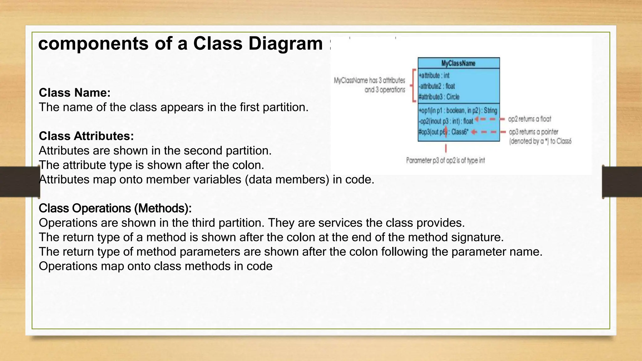
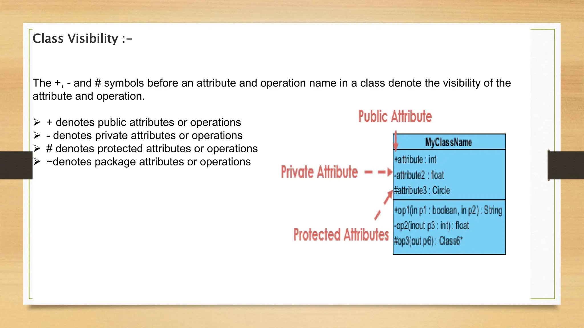
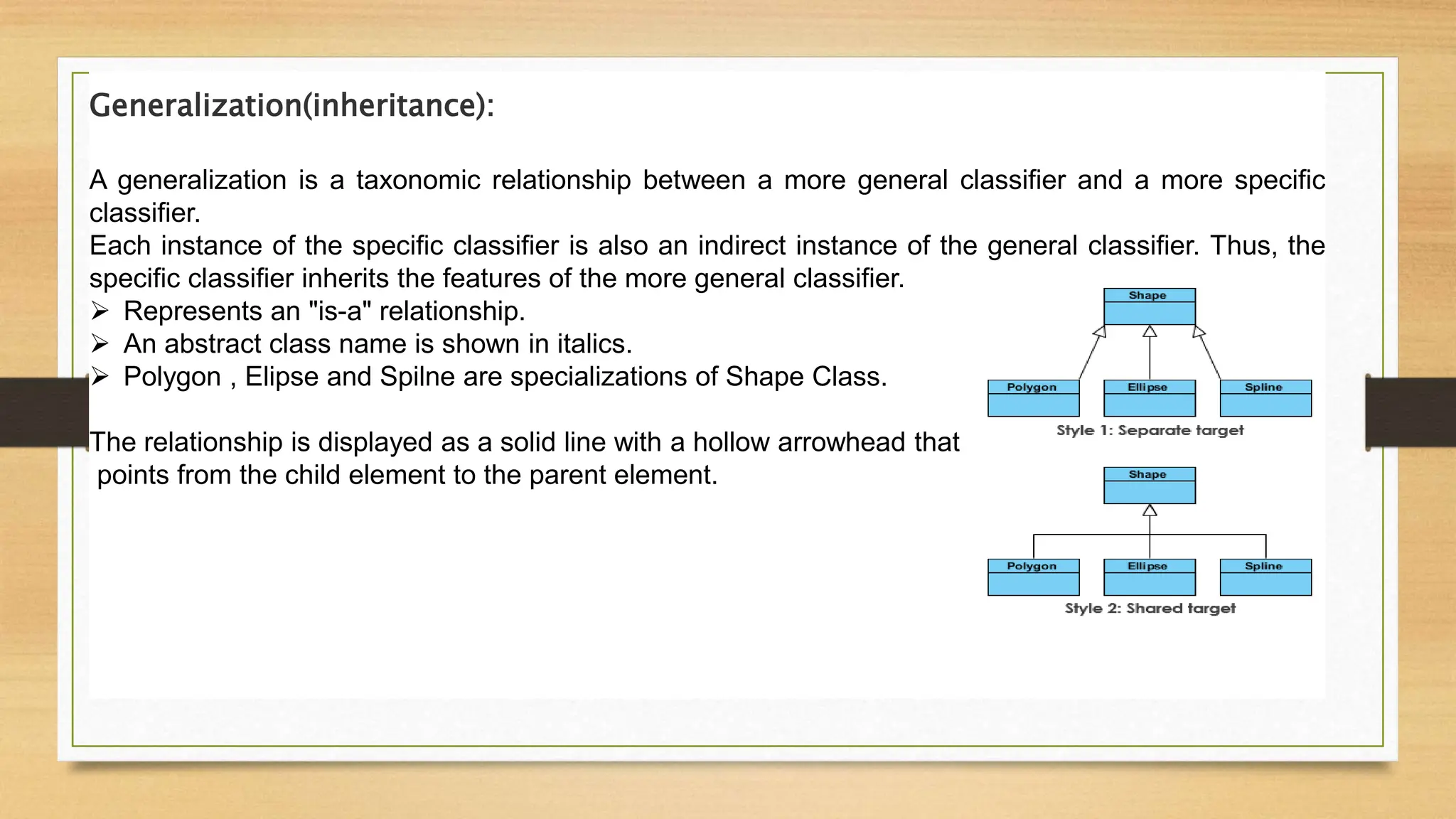
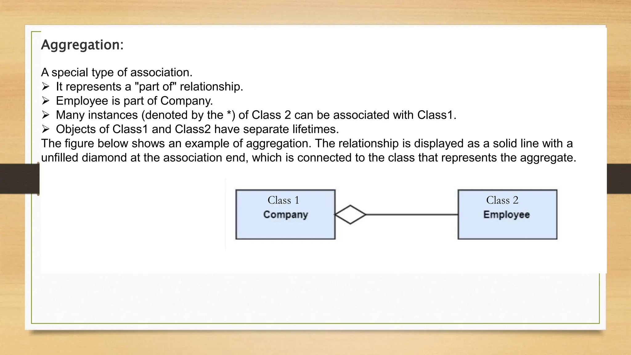
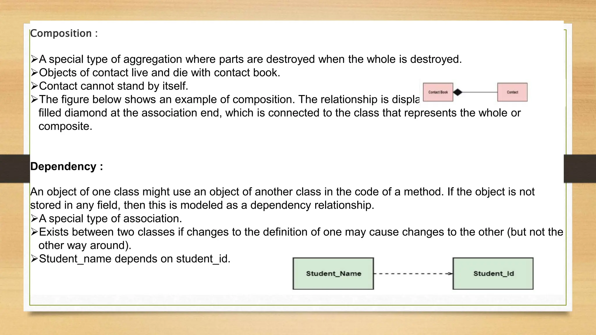
Class diagram
Himesh Nayi :- 210280107093
SOFTWARE ENGINEERING(3150711)
What is class diagram ?
The UML Class diagram is a graphical notation used to construct and visualize object oriented systems. A class
diagram in the Unified Modeling Language (UML) is a type of static structure diagram that describes the structure of
a system by showing the system's:
 classes,
 their attributes,
 operations (or methods),
 and the relationships among objects.
It shows the object classes in the system and the association between these classes.
we can draw the diagram of the system using identifying classes and their relationship.
What is a purpose of class diagram ?
 It analyses and designs a static view of an application.
 It describes the major responsibilities of a system.
 It is a base for component and deployment diagrams.
 It incorporates forward and reverse engineering.
components of a Class Diagram :-
Class Name:
The name of the class appears in the first partition.
Class Attributes:
Attributes are shown in the second partition.
The attribute type is shown after the colon.
Attributes map onto member variables (data members) in code.
Class Operations (Methods):
Operations are shown in the third partition. They are services the class provides.
The return type of a method is shown after the colon at the end of the method signature.
The return type of method parameters are shown after the colon following the parameter name.
Operations map onto class methods in code
Class Visibility :-
The +, - and # symbols before an attribute and operation name in a class denote the visibility of the
attribute and operation.
 + denotes public attributes or operations
 - denotes private attributes or operations
 # denotes protected attributes or operations
 ~denotes package attributes or operations
Generalization(inheritance):
A generalization is a taxonomic relationship between a more general classifier and a more specific
classifier.
Each instance of the specific classifier is also an indirect instance of the general classifier. Thus, the
specific classifier inherits the features of the more general classifier.
 Represents an "is-a" relationship.
 An abstract class name is shown in italics.
 Polygon , Elipse and Spilne are specializations of Shape Class.
The relationship is displayed as a solid line with a hollow arrowhead that
points from the child element to the parent element.
Association :
Associations are relationships between classes in a UML Class Diagram. They are represented by a solid
line between classes. Associations are typically named using a verb or verb phrase which reflects the real
world problem domain.
Cardinality :
 Cardinality is expressed in terms of:
 one to one
 one to many
 many to many
Aggregation:
A special type of association.
 It represents a "part of" relationship.
 Employee is part of Company.
 Many instances (denoted by the *) of Class 2 can be associated with Class1.
 Objects of Class1 and Class2 have separate lifetimes.
The figure below shows an example of aggregation. The relationship is displayed as a solid line with a
unfilled diamond at the association end, which is connected to the class that represents the aggregate.
Class 1 Class 2
Composition :
A special type of aggregation where parts are destroyed when the whole is destroyed.
Objects of contact live and die with contact book.
Contact cannot stand by itself.
The figure below shows an example of composition. The relationship is displayed as a solid line with a
filled diamond at the association end, which is connected to the class that represents the whole or
composite.
Dependency :
An object of one class might use an object of another class in the code of a method. If the object is not
stored in any field, then this is modeled as a dependency relationship.
A special type of association.
Exists between two classes if changes to the definition of one may cause changes to the other (but not the
other way around).
Student_name depends on student_id.
Class Diagram Example: Order System

210280107093_CLASS_DIAGRAM.pptx

  • 1.
    Class diagram Himesh Nayi:- 210280107093 SOFTWARE ENGINEERING(3150711)
  • 2.
    What is classdiagram ? The UML Class diagram is a graphical notation used to construct and visualize object oriented systems. A class diagram in the Unified Modeling Language (UML) is a type of static structure diagram that describes the structure of a system by showing the system's:  classes,  their attributes,  operations (or methods),  and the relationships among objects. It shows the object classes in the system and the association between these classes. we can draw the diagram of the system using identifying classes and their relationship.
  • 3.
    What is apurpose of class diagram ?  It analyses and designs a static view of an application.  It describes the major responsibilities of a system.  It is a base for component and deployment diagrams.  It incorporates forward and reverse engineering.
  • 4.
    components of aClass Diagram :- Class Name: The name of the class appears in the first partition. Class Attributes: Attributes are shown in the second partition. The attribute type is shown after the colon. Attributes map onto member variables (data members) in code. Class Operations (Methods): Operations are shown in the third partition. They are services the class provides. The return type of a method is shown after the colon at the end of the method signature. The return type of method parameters are shown after the colon following the parameter name. Operations map onto class methods in code
  • 5.
    Class Visibility :- The+, - and # symbols before an attribute and operation name in a class denote the visibility of the attribute and operation.  + denotes public attributes or operations  - denotes private attributes or operations  # denotes protected attributes or operations  ~denotes package attributes or operations
  • 6.
    Generalization(inheritance): A generalization isa taxonomic relationship between a more general classifier and a more specific classifier. Each instance of the specific classifier is also an indirect instance of the general classifier. Thus, the specific classifier inherits the features of the more general classifier.  Represents an "is-a" relationship.  An abstract class name is shown in italics.  Polygon , Elipse and Spilne are specializations of Shape Class. The relationship is displayed as a solid line with a hollow arrowhead that points from the child element to the parent element.
  • 7.
    Association : Associations arerelationships between classes in a UML Class Diagram. They are represented by a solid line between classes. Associations are typically named using a verb or verb phrase which reflects the real world problem domain. Cardinality :  Cardinality is expressed in terms of:  one to one  one to many  many to many
  • 8.
    Aggregation: A special typeof association.  It represents a "part of" relationship.  Employee is part of Company.  Many instances (denoted by the *) of Class 2 can be associated with Class1.  Objects of Class1 and Class2 have separate lifetimes. The figure below shows an example of aggregation. The relationship is displayed as a solid line with a unfilled diamond at the association end, which is connected to the class that represents the aggregate. Class 1 Class 2
  • 9.
    Composition : A specialtype of aggregation where parts are destroyed when the whole is destroyed. Objects of contact live and die with contact book. Contact cannot stand by itself. The figure below shows an example of composition. The relationship is displayed as a solid line with a filled diamond at the association end, which is connected to the class that represents the whole or composite. Dependency : An object of one class might use an object of another class in the code of a method. If the object is not stored in any field, then this is modeled as a dependency relationship. A special type of association. Exists between two classes if changes to the definition of one may cause changes to the other (but not the other way around). Student_name depends on student_id.
  • 10.